EP0547009A1 - Hydraulikzylinder, insbesondere zum Durchführen einer Hilfskraftsteuerung und ähnlicher Mechanismen - Google Patents
Hydraulikzylinder, insbesondere zum Durchführen einer Hilfskraftsteuerung und ähnlicher Mechanismen Download PDFInfo
- Publication number
- EP0547009A1 EP0547009A1 EP92830654A EP92830654A EP0547009A1 EP 0547009 A1 EP0547009 A1 EP 0547009A1 EP 92830654 A EP92830654 A EP 92830654A EP 92830654 A EP92830654 A EP 92830654A EP 0547009 A1 EP0547009 A1 EP 0547009A1
- Authority
- EP
- European Patent Office
- Prior art keywords
- tubular body
- tubular core
- cylindrical tubular
- seatings
- skirt
- Prior art date
- Legal status (The legal status is an assumption and is not a legal conclusion. Google has not performed a legal analysis and makes no representation as to the accuracy of the status listed.)
- Granted
Links
Images

Classifications
-
- B—PERFORMING OPERATIONS; TRANSPORTING
- B62—LAND VEHICLES FOR TRAVELLING OTHERWISE THAN ON RAILS
- B62D—MOTOR VEHICLES; TRAILERS
- B62D5/00—Power-assisted or power-driven steering
- B62D5/06—Power-assisted or power-driven steering fluid, i.e. using a pressurised fluid for most or all the force required for steering a vehicle
- B62D5/10—Power-assisted or power-driven steering fluid, i.e. using a pressurised fluid for most or all the force required for steering a vehicle characterised by type of power unit
- B62D5/12—Piston and cylinder
-
- B—PERFORMING OPERATIONS; TRANSPORTING
- B62—LAND VEHICLES FOR TRAVELLING OTHERWISE THAN ON RAILS
- B62D—MOTOR VEHICLES; TRAILERS
- B62D5/00—Power-assisted or power-driven steering
- B62D5/06—Power-assisted or power-driven steering fluid, i.e. using a pressurised fluid for most or all the force required for steering a vehicle
- B62D5/20—Power-assisted or power-driven steering fluid, i.e. using a pressurised fluid for most or all the force required for steering a vehicle specially adapted for particular type of steering gear or particular application
- B62D5/22—Power-assisted or power-driven steering fluid, i.e. using a pressurised fluid for most or all the force required for steering a vehicle specially adapted for particular type of steering gear or particular application for rack-and-pinion type
Definitions
- the present invention relates to a hydraulic actuator, in particular for activating servocontrols and the like mechanisms, comprising: a cylindrical tubular body; a pair of closing elements, each of which is hermetically engaged to one end of the cylindrical tubular body; a piston slidably and sealingly engaged in the cylindrical tubular body and carrying at least one drive rod slidably and sealingly passing through at least one of said closing elements, said piston defining a first pressurization chamber and a second pressurization chamber within the cylindrical tubular body; at least first and second hydraslic coupling elements operatively engaged with the cylindrical tubular body and respectively opening into the first and second pressurization chambers; a plurality of attachment tailpieces rigidly connected to the cylindrical tubular body for enabling engagement of the actuator with a bearing structure.
- the actuator is especially conceived for power steerings of motor-vehicles and the like. Therefore, in the progress of the present description reference will be particularly made to this technological field, without however intending to limit the possibilities of use of the invention in other fields.
- This hydraulic actuator comprises a cylindrical tubular body to the opposite ends of which respective closing elements are hermetically engaged, one of which elements is normally formed of one piece construction with the body of the steering gear case.
- a piston integrally carried by a drive rod completely passing through the tubular body itself, emerging therefrom through the closing elements and integrally connected to the rack at one of the ends thereof.
- the piston defines a first and a-second pressurization chambers into which, through the tubular body itself, respective hydraslic coupling elements open, which hydraslic coupling elements are connected to a selection valve to be activated at the moment that a steering occurs.
- the selection valve will selectively cause the delivery of working fluid under pressure into the first or the second pressurization chamber, depending on the direction of the steering movement, so that through the piston and drive rod, longitudinal forces are transmitted to the rack that will facilitate the driver's manoeuvring.
- Pressure die-casting enables all necessary tailpieces to be formed of one piece construction with the cylindrical body, in order to enable the actuator to be for example fastened to the motor-vehicle structure and/or the hydraulic coupling elements to be suitably and readily engaged.
- aluminium alloys anti the like used in this solution enable heat to be easily eliminated, to advantage of a greater operating reliability of the actuator.
- the produced pieces must be submitted, one by one, to severe inspections for ascertaining their perfect hermetic tightness.
- Pieces that do not overcome the tightness test are recovered by means of an impregnation process aiming at closing the porosities present in the material.
- the impregnation process for carrying out the impregnation process the faulty piece, previously degreased and dried, needs to be introduced into a vessel inside which the vacuum is created to 99%.
- the workpiece must be held under vacuum for an important period of time, in the order of 20 minutes.
- a suitable compound containing resins and/or metal parts in a colloidal state is introduced into the vessel.
- the colloidal compound impregnates the workpiece filling the porosities thereof.
- the workpiece must be submitted to a washing and drying step so that the colloidal compound may dry within the porosities.
- Pieces submitted to the impregnation process must be again submitted to the tightness test and discarded if they do not give successful results in this second test too.
- the main object of the present invention is to eliminate the above mentioned problems present in the known art.
- the invention aims at making fluid- operated actuators that, while keeping the advantages proper to the products made by die-casting an aluminium alloy or similar material, are capable of offering a complete and sure hermetic tightness, so that the above described impregnation processes do not need to be carried out any longer.
- Another object of the invention is to remarkably facilitate the boring and finishing operations on the inner surface of the cylindrical tubular body after die-casting.
- a hydraulic actuator in particular for activating servocontrols and the like mechanisms, characterized in that said cylindrical tubular body comprises: a tubular core in the form of an extruded section, having the respective ends hermetically engaged by said closing elements and carrying connection seatings for sealingly engaging said first and second hydraulic coupling elements; a skirt die-cast around said tubular core, carrying said attachment tailpieces and exhibiting access openings each defined at one of said connection seatings for enabling said connection seatings to be engaged by the hydraulic coupling elements; anchoring means formed on said tubular core and substantially defining undercuts designed to be filled with the die-cast material forming the skirt, in order to ensure the integral anchoring of said skirt to the tubular core.
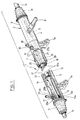
- a hydraulic actuator in particular for activating servocontrols and the like mechanisms in accordance with the present invention has been generally identified by reference numeral 1.
- the actuator 1 is interlocked to a steering gear 2 for motor-vehicles conventionally comprising a so-called steering gear case 3 within which a rack 4 is slidably guided, which rack is longitudinally movable upon command of a pinion 5 keyed onto the end of a shaft 6 driven in rotation by a flywheel, not shown.
- the hydraulic actuator 1 comprises a cylindrical tubular body 7 externally provided with attachment tailpieces 7a suitably distributed and shaped so as to enable fastening of the actuator 7 and the steering gear case 3 to the motor-vehicle structure.
- closing elements 8 Hermetically engaged to the opposite-ends of the tubular body 7, upon interposition of sealing rings 8a, are respective closing elements 8.
- the closing element not shown is joined to the corresponding end of the steering gear case 3 in a unitary manner, but at all events this closing element is not of importance to the ends of the present invention.
- the drive rod 10 has a longitudinal extension greater than that of the cylindrical tubular body 7 and passes through the closing elements 8 in a slidable and sealing manner.
- the presence of the piston 9 divides the longitudinal extension of the drive rod 10 into a first portion 10a and a second portion 10b.
- the first portion 10a located to the left with reference to Fig. 1, is connected to a first arm 12 by a ball joint housed in a first protection bellows 11 fastened to one end of the cylindrical tubular body 7.
- the arm 12 is designed to transmit the steering movements to a first motor-vehicle wheel.
- the second portion 10b integrally carries said rack 4 and extends beyond the steering gear case 3 for connection to a second arm 14 by another ball joint housed in a second protection bellows 13.
- the second arm 14 is designed to transmit the steering movements to a second motor-vehicle wheel.
- the ball joints connecting the arms 12, 14 to the wheels have not been shown as known per se and conventional, and at all events they are not of importance to the ends of the invention.
- the piston 9 defines a first and a second pressurization chambers 15, 10 into which respective hydraulic coupling elements 17, 18, open. Said coupling elements are operatively and sealingly engaged through the tubular body itself and are connected to respective delivery pipes 19, 20 being part of a conventional hydraulic feed circuit.
- this circuit In a manner known per se, this circuit, not shown in detail as not of importance to the ends of the invention, comprises a fluid pump designed to send high-pressure working fluid, usually oil; to a selection valve.
- the selection valve is, for example, operatively connected to the rack 4 and/or the pinion 5 so that it can detect the steering movements transmitted by the driver to the pinion and the rack and consequently selectively send fluid under pressure to the first or second pressurization chambers 15, 16, depending on the direction according to which the detected steering movement takes place.
- said valve will send working fluid under pressure to the first pressurization chamber 15, that is to say the chamber disposed to the left of piston 9 in Fig. 1, when the steering movement demands an axial displacement of the rack 4 to the right. Therefore the rack 4 in its movement is assisted by the thrust exerted on the piston 9 by effect of the pressure of the fluid sent to the first pressurization chamber 15.
- fluid under pressure will be sent to the second pressurization chamber 16 when the steering movement demands an axial displacement of the rack 4 to the left.
- the cylindrical tubular body 7 comprises a tubular core 21 in the form of an extruded section, externally coated with a skirt 22 preferably made of an aluminium alloy material or another light alloy material, die-cast around the core and carrying said attachment tailpieces 7a in a unitary manner.
- the tubular core 21 is preferably formed from an extruded section made of a light alloy, preferably an aluminium alloy, but it can also be made of other materials or alloys.
- the tubular core 21 exhibits a suitably-ground inner cylindrical surface 21a along which said piston 9 sealingly slides.
- the closing elements 8 and the cylindrical tubular body 7 are hermetically sealed by sealing rings 8a.
- the tubular core 21 is externally provided with anchoring means 23 defining respective undercuts 24 that, during die-casting of the skirt 22, lend themselves to be filled with the material forming the skirt itself so that they can ensure the integral anchoring of said skirt to the core 21.
- the anchoring means 23 comprises a plurality of longitudinal ribs 25 extending parallelly along the tubular core 21, disposed and shaped in such a manner that the undercuts 24 are substantially constituted by dovetail grooves 24a homogeneously distributed on the outer circumferential extension of the tubular core 21.
- connection seatings 26, 27 are also advantageously provided on the tubular core 21, which seatings are designed to sealingly engage said first and second hydraulic coupling elements 17, 18.
- the connection seatings 26, 27 are defined by flarings of truncated conical form formed on radial through holes 26b, 27b extending through respective blocks 26a (only one of which is shown) projecting from the tubular core 21.
- the blocks 26a can be obtained for example as a result of a milling operation carried out, before die-casting of the skirt 22, on an auxiliary rib 28 (shown in dotted line) extending, in an original manner, over the entire longitudinal extension of the section forming the tubular core 21.
- auxiliary rib 28 may also be maintained untouched and incorporated in the skirt 22, following die-casting of said skirt around the tubular core 21.
- the thickness of the skirt 22 is greater than the height of the blocks 26a with respect to the outer surface of the core 21.
- threaded seatings 29a are preferably formed (only one of which is shown) into which the hydraulic coupling elements 17,18 are operatively engaged by screwing.
- the thickness of the skirt 22 may be provided to be lower than the height of the blocks 26a so that said blocks are directly exposed externally of the actuator 1 through the respective access openings 29, 30 defined in the skirt 22.
- the threaded seatings 29a will be directly formed in the blocks 26a.
- the invention attains the intended purposes.
- tubular core 21 made in the form of an extruded section, ensures a perfect tightness against the working fluid under pressure, by virtue of the complete absence of structural defects, such as blowholes and shrinkage cavities, which are typical of die-castings.
- the perfect hydraulic tightness of the actuator 1 under working conditions is also ensured by the fact that the hermetic sealings at the hydraulic coupling elements 17, 18 and the closing elements 8 take place directly on the tubular core 21.
- the die-cast skirt 22 is completely isolated from the working fluid under pressure, so that the presence therein of blowholes or shrinkage cavities typical of die-castings, does not affect the good operation and reliability of the actuator in question.
- tubular core is formed with an extruded section, it is no longer necessary to remove important amounts of machining allowances during the finish operations executed on the inner surface of the cylindrical tubular body, which on the contrary happens in the known art.
- finish operations are further facilitated, as compared to die-castings of the known art, by the best workability of the extruded member forming the tubular core 21, due to its greater structural compactness.
- the structural compactness of the extruder section also brings about improved mechanical characteristics that, as compared to conventional die-castings, better meet the operating requirements of the piston 9-cylindrical tubular body 7 assembly.
- the invention enables more reliable hydraulic actuators to be produced at greatly reduced costs as compared to those of the known art, since all the long and expensive impregnation processes for recovery of the faulty pieces are eliminated, as well as most of the mechanical finish workings on the workpieces.
Landscapes
- Engineering & Computer Science (AREA)
- Chemical & Material Sciences (AREA)
- Combustion & Propulsion (AREA)
- Transportation (AREA)
- Mechanical Engineering (AREA)
- Actuator (AREA)
- Power Steering Mechanism (AREA)
- Vehicle Body Suspensions (AREA)
- Valve Device For Special Equipments (AREA)
- Fluid-Pressure Circuits (AREA)
Applications Claiming Priority (2)
| Application Number | Priority Date | Filing Date | Title |
|---|---|---|---|
| ITMI913339A IT1252202B (it) | 1991-12-12 | 1991-12-12 | Attuatore idraulico, particolarmente per l'attuazione di servocomandi e simili. |
| ITMI913339 | 1991-12-12 |
Publications (2)
| Publication Number | Publication Date |
|---|---|
| EP0547009A1 true EP0547009A1 (de) | 1993-06-16 |
| EP0547009B1 EP0547009B1 (de) | 1996-05-29 |
Family
ID=11361323
Family Applications (1)
| Application Number | Title | Priority Date | Filing Date |
|---|---|---|---|
| EP92830654A Expired - Lifetime EP0547009B1 (de) | 1991-12-12 | 1992-12-04 | Hydraulikzylinder, insbesondere zum Durchführen einer Hilfskraftsteuerung und ähnlicher Mechanismen |
Country Status (7)
| Country | Link |
|---|---|
| EP (1) | EP0547009B1 (de) |
| JP (1) | JPH05248412A (de) |
| AT (1) | ATE138619T1 (de) |
| CA (1) | CA2085183A1 (de) |
| DE (1) | DE69211105T2 (de) |
| ES (1) | ES2090583T3 (de) |
| IT (1) | IT1252202B (de) |
Cited By (5)
| Publication number | Priority date | Publication date | Assignee | Title |
|---|---|---|---|---|
| GB2275662A (en) * | 1993-03-02 | 1994-09-07 | Gloster Saro Ltd | Vehicle steering systems |
| WO1998023477A1 (en) * | 1996-11-29 | 1998-06-04 | Adwest Steering Ltd. | A power assisted steering mechanism |
| US6928922B2 (en) | 2003-10-23 | 2005-08-16 | Smc Kabushiki Kaisha | Lubricating structure for hydraulic driving apparatus |
| EP1395480A4 (de) * | 2001-05-18 | 2006-03-22 | Trw Inc | Zahnstangenbuchse mit zweiteiliger dichtung |
| US7055320B2 (en) | 2003-08-01 | 2006-06-06 | Smc Kabushiki Kaisha | Actuator |
Citations (5)
| Publication number | Priority date | Publication date | Assignee | Title |
|---|---|---|---|---|
| US3069209A (en) * | 1958-07-16 | 1962-12-18 | Alfred F Bauer | Method of bonding a bi-metallic casting |
| DE2538778A1 (de) * | 1974-09-13 | 1976-03-25 | Ford Werke Ag | Zahnstangen-hilfskraftlenkung fuer kraftfahrzeuge |
| EP0340896A2 (de) * | 1988-05-06 | 1989-11-08 | General Motors Corporation | Lenkgetriebe mit einem Metall-/Plastik-Gehäuse |
| WO1990005083A1 (de) * | 1988-11-05 | 1990-05-17 | Volkswagen Aktiengesellschaft | Leichtmetall-gussgehäuse einer zahnstangenlenkung |
| DE4019693C1 (en) * | 1990-06-21 | 1991-09-26 | Georg Fischer Ag, Schaffhausen, Ch | Motor vehicle tower steering - has hydraulic ducts to cylinder chambers with rack adjoining pinion |
-
1991
- 1991-12-12 IT ITMI913339A patent/IT1252202B/it active IP Right Grant
-
1992
- 1992-12-04 DE DE69211105T patent/DE69211105T2/de not_active Expired - Fee Related
- 1992-12-04 EP EP92830654A patent/EP0547009B1/de not_active Expired - Lifetime
- 1992-12-04 AT AT92830654T patent/ATE138619T1/de not_active IP Right Cessation
- 1992-12-04 ES ES92830654T patent/ES2090583T3/es not_active Expired - Lifetime
- 1992-12-11 CA CA002085183A patent/CA2085183A1/en not_active Abandoned
- 1992-12-14 JP JP4353478A patent/JPH05248412A/ja active Pending
Patent Citations (5)
| Publication number | Priority date | Publication date | Assignee | Title |
|---|---|---|---|---|
| US3069209A (en) * | 1958-07-16 | 1962-12-18 | Alfred F Bauer | Method of bonding a bi-metallic casting |
| DE2538778A1 (de) * | 1974-09-13 | 1976-03-25 | Ford Werke Ag | Zahnstangen-hilfskraftlenkung fuer kraftfahrzeuge |
| EP0340896A2 (de) * | 1988-05-06 | 1989-11-08 | General Motors Corporation | Lenkgetriebe mit einem Metall-/Plastik-Gehäuse |
| WO1990005083A1 (de) * | 1988-11-05 | 1990-05-17 | Volkswagen Aktiengesellschaft | Leichtmetall-gussgehäuse einer zahnstangenlenkung |
| DE4019693C1 (en) * | 1990-06-21 | 1991-09-26 | Georg Fischer Ag, Schaffhausen, Ch | Motor vehicle tower steering - has hydraulic ducts to cylinder chambers with rack adjoining pinion |
Cited By (5)
| Publication number | Priority date | Publication date | Assignee | Title |
|---|---|---|---|---|
| GB2275662A (en) * | 1993-03-02 | 1994-09-07 | Gloster Saro Ltd | Vehicle steering systems |
| WO1998023477A1 (en) * | 1996-11-29 | 1998-06-04 | Adwest Steering Ltd. | A power assisted steering mechanism |
| EP1395480A4 (de) * | 2001-05-18 | 2006-03-22 | Trw Inc | Zahnstangenbuchse mit zweiteiliger dichtung |
| US7055320B2 (en) | 2003-08-01 | 2006-06-06 | Smc Kabushiki Kaisha | Actuator |
| US6928922B2 (en) | 2003-10-23 | 2005-08-16 | Smc Kabushiki Kaisha | Lubricating structure for hydraulic driving apparatus |
Also Published As
| Publication number | Publication date |
|---|---|
| DE69211105T2 (de) | 1996-10-24 |
| ATE138619T1 (de) | 1996-06-15 |
| ES2090583T3 (es) | 1996-10-16 |
| ITMI913339A1 (it) | 1993-06-12 |
| IT1252202B (it) | 1995-06-05 |
| CA2085183A1 (en) | 1993-06-13 |
| EP0547009B1 (de) | 1996-05-29 |
| JPH05248412A (ja) | 1993-09-24 |
| DE69211105D1 (de) | 1996-07-04 |
| ITMI913339A0 (it) | 1991-12-12 |
Similar Documents
| Publication | Publication Date | Title |
|---|---|---|
| US6047788A (en) | Hydraulic power steering system with dual, double-acting piston-cylinder units | |
| JP5687208B2 (ja) | ラックハウジングの向上した圧入接続 | |
| EP0547009B1 (de) | Hydraulikzylinder, insbesondere zum Durchführen einer Hilfskraftsteuerung und ähnlicher Mechanismen | |
| JPS636394B2 (de) | ||
| US5396969A (en) | Servo control, especially power steering for motor vehicles | |
| KR910007260B1 (ko) | 로터리-밸브 랙 및 피니언 동력스티어링기어 하우징 | |
| US4573399A (en) | Piston and cylinder assembly, a power assisted steering gear which includes such an assembly and a method of forming a piston for such an assembly | |
| US4189024A (en) | Auxiliary power steering for motor vehicles | |
| US3926070A (en) | Rack-and-pinion steering gear box incorporating a damper for motor vehicles | |
| US5868216A (en) | Hydraulic rack-and-pinion steering assembly | |
| US6363833B1 (en) | Piston for hydraulic power assist rack and pinion steering system | |
| US3882762A (en) | Cast piston with hollow core and head cover | |
| US5711395A (en) | Rotary slide valve for power-assisted steering mechanisms of motor vehicles | |
| US5390755A (en) | Power steering servo control for motor vehicles | |
| US4621703A (en) | Hydraulic auxiliary power steering, especially for motor vehicles | |
| US2858805A (en) | Means for reducing relief valve squeal in a hydraulic power steering gear | |
| US2847868A (en) | Hydraulic steering gear with a gear rack disposed intermediate piston heads | |
| US4294325A (en) | Power assisted steering system for vehicles | |
| GB2045869A (en) | Rotary positive-displacement fluid machines. | |
| RU2494906C2 (ru) | Корпус рулевой рейки с поперечными сужениями | |
| EP0467333B1 (de) | Hydraulische hilfskraftverstärkte Lenkeinrichtung | |
| US6694615B2 (en) | Method for manufacturing a welded hydraulic cylinder for reducing hoop stress | |
| US3608433A (en) | Valve arrangement in the working pistion of a pressure-medium operating cylinder | |
| JPH0735237A (ja) | ピストンとその製造方法 | |
| RU2047805C1 (ru) | Поворотный пневмопривод с ручным дублером |
Legal Events
| Date | Code | Title | Description |
|---|---|---|---|
| PUAI | Public reference made under article 153(3) epc to a published international application that has entered the european phase |
Free format text: ORIGINAL CODE: 0009012 |
|
| AK | Designated contracting states |
Kind code of ref document: A1 Designated state(s): AT BE DE DK ES FR GB GR IE NL PT SE |
|
| 17P | Request for examination filed |
Effective date: 19931215 |
|
| 17Q | First examination report despatched |
Effective date: 19951117 |
|
| GRAH | Despatch of communication of intention to grant a patent |
Free format text: ORIGINAL CODE: EPIDOS IGRA |
|
| GRAA | (expected) grant |
Free format text: ORIGINAL CODE: 0009210 |
|
| AK | Designated contracting states |
Kind code of ref document: B1 Designated state(s): AT BE DE DK ES FR GB GR IE NL PT SE |
|
| PG25 | Lapsed in a contracting state [announced via postgrant information from national office to epo] |
Ref country code: NL Free format text: LAPSE BECAUSE OF FAILURE TO SUBMIT A TRANSLATION OF THE DESCRIPTION OR TO PAY THE FEE WITHIN THE PRESCRIBED TIME-LIMIT Effective date: 19960529 Ref country code: GR Free format text: LAPSE BECAUSE OF FAILURE TO SUBMIT A TRANSLATION OF THE DESCRIPTION OR TO PAY THE FEE WITHIN THE PRESCRIBED TIME-LIMIT Effective date: 19960529 Ref country code: DK Effective date: 19960529 Ref country code: BE Effective date: 19960529 |
|
| REF | Corresponds to: |
Ref document number: 138619 Country of ref document: AT Date of ref document: 19960615 Kind code of ref document: T |
|
| REG | Reference to a national code |
Ref country code: IE Ref legal event code: FG4D Free format text: 68533 |
|
| REF | Corresponds to: |
Ref document number: 69211105 Country of ref document: DE Date of ref document: 19960704 |
|
| ET | Fr: translation filed | ||
| PG25 | Lapsed in a contracting state [announced via postgrant information from national office to epo] |
Ref country code: SE Effective date: 19960829 Ref country code: PT Effective date: 19960829 |
|
| REG | Reference to a national code |
Ref country code: ES Ref legal event code: FG2A Ref document number: 2090583 Country of ref document: ES Kind code of ref document: T3 |
|
| NLV1 | Nl: lapsed or annulled due to failure to fulfill the requirements of art. 29p and 29m of the patents act | ||
| REG | Reference to a national code |
Ref country code: ES Ref legal event code: FG2A Ref document number: 2090583 Country of ref document: ES Kind code of ref document: T3 |
|
| PG25 | Lapsed in a contracting state [announced via postgrant information from national office to epo] |
Ref country code: IE Free format text: LAPSE BECAUSE OF NON-PAYMENT OF DUE FEES Effective date: 19961204 Ref country code: GB Effective date: 19961204 Ref country code: AT Effective date: 19961204 |
|
| PLBE | No opposition filed within time limit |
Free format text: ORIGINAL CODE: 0009261 |
|
| 26N | No opposition filed | ||
| GBPC | Gb: european patent ceased through non-payment of renewal fee |
Effective date: 19961204 |
|
| PG25 | Lapsed in a contracting state [announced via postgrant information from national office to epo] |
Ref country code: FR Effective date: 19970829 |
|
| PG25 | Lapsed in a contracting state [announced via postgrant information from national office to epo] |
Ref country code: DE Effective date: 19970902 |
|
| REG | Reference to a national code |
Ref country code: FR Ref legal event code: ST |
|
| PG25 | Lapsed in a contracting state [announced via postgrant information from national office to epo] |
Ref country code: ES Free format text: LAPSE BECAUSE OF NON-PAYMENT OF DUE FEES Effective date: 19971205 |
|
| REG | Reference to a national code |
Ref country code: ES Ref legal event code: FD2A Effective date: 19980113 |