EP0547527A1 - Einrichtung zur Übertragung von Steuerungsinformation zur Verwendung in einem Zeitmultiplexierübertragungssystem - Google Patents
Einrichtung zur Übertragung von Steuerungsinformation zur Verwendung in einem Zeitmultiplexierübertragungssystem Download PDFInfo
- Publication number
- EP0547527A1 EP0547527A1 EP92121175A EP92121175A EP0547527A1 EP 0547527 A1 EP0547527 A1 EP 0547527A1 EP 92121175 A EP92121175 A EP 92121175A EP 92121175 A EP92121175 A EP 92121175A EP 0547527 A1 EP0547527 A1 EP 0547527A1
- Authority
- EP
- European Patent Office
- Prior art keywords
- control information
- time
- division multiplex
- information transmission
- time division
- Prior art date
- Legal status (The legal status is an assumption and is not a legal conclusion. Google has not performed a legal analysis and makes no representation as to the accuracy of the status listed.)
- Withdrawn
Links
Images



Classifications
-
- H—ELECTRICITY
- H04—ELECTRIC COMMUNICATION TECHNIQUE
- H04J—MULTIPLEX COMMUNICATION
- H04J3/00—Time-division multiplex systems
- H04J3/02—Details
- H04J3/12—Arrangements providing for calling or supervisory signals
Definitions
- the invention relates to a control information transmission apparatus for transmitting control information required for data transmission in time division multiplex communication systems.
- FIG. 7 is a block diagram of a conventional control information insertion and extraction circuit used in such time division multiplex communication systems.
- 51 is a central processing unit (CPU) for controlling the control information transmission apparatus.
- 52 is a serial interface for transmitting the control information.
- 53 is an inserting portion for inserting the transmitting control information.
- 54 is a sending side data transmission line for transmitting data.
- 55 is a receiving side data transmission line for receiving the data.
- 56 is an extracting portion for extracting receive control information.
- 57 is a serial interface for receiving the receive control information.
- the CPU 51 controls both the transmitting and receive control information.
- the transmitting control information is output from the CPU 51 to the sending side data transmission line 54 through the serial interface 52 and the inserting portion 53.
- the receive control information received from the receiving side data transmission line 55 is extracted by the extracting portion 56 and output to the CPU 51 through the serial interface 57.
- FIG. 8 shows a frame format construction of a Y interface primary group.
- the transmitting and receive control information are allocated to a fixed time-slot which is called a service channel.
- 58 is a frame having 24 channels.
- 59 is the head channel (CH 1) of the frame.
- 60 is the frame construction of head channel CH 1 having 8 bits in the channel.
- the CPU 51 extracts the control information from the fixed channel in the data signal received from the receiving side data transmission line 55, or inserts the control signal to be transmitted into the service channel and transmits it to the sending side data transmission line 54.
- a control information transmission apparatus of a first embodiment of the present invention for use in time division multiplex communication systems for allocating the control information necessary for transmitting the data to a part of the user area between the communication equipments connected by the time division multiplex highway comprises a control information transmission area variable setting means for selectively allocating control information in any time slot in order to variably separate the control information transmission area and the user area so that the data are transmitted at selected speeds.
- control information transmission area corresponds to a test function setting transmission area in which the remote loop back information is allocated or a system switching transmission area in which the system data is allocated for changing the routing.
- FIG. 1 shows a communication network embodying the present invention and connected to a time division multiplex highway of a Y interface primary group.
- 1 and 2 are communication apparatus connected to the time division multiplex highway of the Y interface primary group.
- 3 represents N terminal equipments 3-1,..., 3-N connected to the communication apparatus 1.
- 4 represents M terminal equipments 4-1,..., 4-M connected to the communication apparatus 2.
- FIG. 2 is block diagram of a control information insertion and extraction circuit used in the communication apparatus 1 and the communication apparatus 2 for realizing the control information transmission apparatus of the present invention for time division multiplex communication systems.
- 11 is a CPU for controlling the control information insertion and extraction circuit.
- 12 is a serial interface for transmitting the control information.
- 13 is an inserting portion for inserting the transmitting control information.
- 14 is a sending side data transmission line SD for transmitting data.
- 17 is a serial interface for receiving control information.
- 18 is a time-slot information register.
- the inserting portion 13 comprises a time-slot counter 13a for counting time-slots for 24 channels from 1 to 192 by the means of a frame synchronous signal.
- the time-slot counter 13a outputs the counted values as time-slot address information.
- the inserting portion 13 reads out the contents written in the time-slot information register 18 by the time-slot address information. Then, the inserting portion 13 outputs the transmitting control information received from the CPU 11 through the serial interface 12 to the sending side data transmission line 14 in response to the read out contents of the time-slot information register 18.
- the 15 is a receiving side data transmission line RD for receiving data.
- 16 is an extracting portion for extracting receive control information.
- the extracting portion 16 comprises a time-slot counter 16a for counting time-slots for 24 channels from 1 to 192 by means of a the frame synchronous signal.
- the time-slot counter 16a outputs the counted values as time-slot address information.
- the extracting portion 16 reads out the content written in the time-slot information register 18 by the time-slot address information. Then, the extracting portion 16 extracts the receive control information from the main data on the receiving side data transmission line 15 in response to the read out contents of the time-slot information register 18. The receive control information extracted by the extracting portion 16 is output to the CPU 11 through the serial interface 17.
- Identification data which identify the control data or the main data is written into the time-slot information register 18 corresponding to the time-slot address information outputted from the time-slot counter 13a or the time-slot counter 16a. This identification data is written into the time-slot information register 18 in advance by the CPU 11.
- control information transmission apparatus comprises the CPU 11, the time-slot counter 13a, the time-slot counter 16a, the serial interface 12, the inserting portion 13, the sending side data transmission line 14, the receiving side data transmission line 15, the extracting portion 16, the serial interface 17, and the time-slot information register 18.
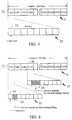
- FIG. 3 shows the frame format of the Y interface primary group of the control information transmission apparatus of the first embodiment of the present invention as used in the time division multiplex communication systems.
- 21 is a frame constructed of 24 channels.
- 22 is the head channel (CH 1) of the frame 21, and 23 is a frame construction of the head channel CH 1 having 8 bits in the channel.
- terminal equipment 3-1 is communicating with the terminal equipment 4-17 and wherein the terminal equipment 3-1 is subsequently requested to communicate with another terminal equipment, e.g. terminal equipment 4-2.
- the communication apparatus 1 and the communication apparatus 2 set a service channel in an unused channel of the user area. That is, each time-slot of the respective channel is selected for setting a control information area or a user area. This setting is executed by the CPU 11.
- the service channel transmission area and the user channel transmission area are newly set for every time-slot in the frame.
- the control information (the information for changing the multiplex format ) is transmitted at a high speed using the service channel transmission area.
- the CPU in the communication apparatus 1 and the CPU in the communication apparatus 2 change the multiplex format.
- the control information can be transmitted at a high speed so that the user transmitting area will not be lost. Accordingly, a dynamic routing is executed at a high speed in the first embodiment.
- a second embodiment of the present invention is explained hereinafter.
- the communication equipment and the control information insertion and extraction circuit of the second embodiment are the same as those of the first embodiment of FIG. 2.
- FIG. 4 shows a format construction in which the service channels are set to each channel corresponding to respective routing in the second embodiment of the present invention.
- 31 is a frame construction having 192 bits.
- 32 shows the head channel CH 1 corresponding to the first routing.
- 33 shows a channel construction of the head channel CH 1 having 8 bits.
- 34 is a time-slot in the channel CH 1.
- 35 is a service channel corresponding to the first routing having 8 kbps transmission capacity.
- 36 is a fourth channel CH 4 corresponding to the second routing.
- 38 shows a channel construction of the channel CH 4.
- 38 is a service channel corresponding to the second routing having 16 kbps transmission rate.
- Every time-slot can be set as a service channel transmission area, the service channel can be set without using any hardware switch for the multiple access used in the primary group interface of an integrated services digital network (ISDN).
- ISDN integrated services digital network
- the setting of the service channel of the third embodiment is explained for a case where a fault occurs in the communication system shown in FIG. 5.
- FIG. 5 shows a construction of another communication system in which the third embodiment is applied.
- 39, 40 are relay equipments.
- 41, 42 are communication apparatus.
- the communication apparatus and the control information insertion and extraction circuit of the third embodiment are the same as those of the first embodiment of FIG. 2.
- 43 is a terminal equipment connected to the communication apparatus 41, and 44 a terminal equipment connected to the communication apparatus 42.
- FIG. 6 shows the format construction of a service channel construction which is set when a fault occurs in the communication system.
- 45 is a frame construction having 192 bits.
- 46 shows a head channel CH 1.
- 47 shows a second channel CH 2.
- 48 is a time-slot in the head channel CH 1.
- 49 is a remote loop back setting area.
- the remote loop back setting area 49 is used in order to send a test pattern from the communication apparatus 41 or 42 to the relay equipment 39 and in order to execute the return test at the relay equipment 39, when the relay equipment 39 fails during the time where terminal equipment 43 and the terminal equipment 44 communicate through the communication apparatus 41, the relay equipment 39 and the communication apparatus 42.
- 50 is a program down load information transmission area in which the communication apparatus 41 and 42 alternatively download the control information in order to make another route which bypasses the failed route.
- the remote back area or program download information transmission area 50 is allocated for a time-slot in the channel.
- the remote loop back setting area 49 and program download information transmission area 5O correspond to the service channel.
- the remote loop back setting area 49 and program download information transmission area 50 are set in many unused channels of the user area by the communication appatatus 41 and the communication apparatus 42.
- the program download information transmission area 5O is used for changing the route at a high speed in order to recover the fault system.
- the control information insertion and extraction circuit can transmit a lot of control information at a high speed during a short time.
- the control information can also be transmitted at high efficiency with a low loss of the user transmitting area. Accordingly, a dynamic routing is executed at a high speed in the first embodiment.
- the route changing is executed at a high speed in order to recover the fault system.
Landscapes
- Engineering & Computer Science (AREA)
- Computer Networks & Wireless Communication (AREA)
- Signal Processing (AREA)
- Time-Division Multiplex Systems (AREA)
- Small-Scale Networks (AREA)
Applications Claiming Priority (2)
| Application Number | Priority Date | Filing Date | Title |
|---|---|---|---|
| JP351754/91 | 1991-12-16 | ||
| JP3351754A JPH05167549A (ja) | 1991-12-16 | 1991-12-16 | 時分割多重通信システムにおける制御情報伝送方式 |
Publications (1)
| Publication Number | Publication Date |
|---|---|
| EP0547527A1 true EP0547527A1 (de) | 1993-06-23 |
Family
ID=18419378
Family Applications (1)
| Application Number | Title | Priority Date | Filing Date |
|---|---|---|---|
| EP92121175A Withdrawn EP0547527A1 (de) | 1991-12-16 | 1992-12-11 | Einrichtung zur Übertragung von Steuerungsinformation zur Verwendung in einem Zeitmultiplexierübertragungssystem |
Country Status (3)
| Country | Link |
|---|---|
| US (1) | US5323383A (de) |
| EP (1) | EP0547527A1 (de) |
| JP (1) | JPH05167549A (de) |
Cited By (2)
| Publication number | Priority date | Publication date | Assignee | Title |
|---|---|---|---|---|
| EP0760563A1 (de) * | 1995-08-29 | 1997-03-05 | ALCATEL BELL Naamloze Vennootschap | Mehrfachrahmenstruktur und Kommunikationsprotokoll für ein Übertragungsnetz |
| WO1999004526A1 (de) * | 1997-07-15 | 1999-01-28 | Deutsche Telekom Ag | Verfahren zur übertragung von signalisierungs- und steuerinformationen für wellenlängenmultiplex-netze zur optischen, fasergebundenen informationsübertragung |
Families Citing this family (7)
| Publication number | Priority date | Publication date | Assignee | Title |
|---|---|---|---|---|
| JP3260950B2 (ja) * | 1994-02-18 | 2002-02-25 | 松下電器産業株式会社 | データ通信装置 |
| US5699356A (en) * | 1995-07-17 | 1997-12-16 | Mci Communication | System and method for personal communication system dynamic channel allocation |
| DE59610494D1 (de) * | 1995-09-15 | 2003-07-10 | Siemens Ag | Verfahren zur Auswertung von leistungsmerkmalbezogenen Nachrichten in einer programmgesteuerten Kommunikationseinrichtung |
| US7406103B2 (en) * | 2003-02-24 | 2008-07-29 | Samsung Electronics Co, Ltd. | Method and apparatus for transmitting data in Gigabit Ethernet passive optical network |
| US20040243910A1 (en) * | 2003-05-29 | 2004-12-02 | Mcleod Gordon R. | Packet data recovery system |
| JP2005284848A (ja) * | 2004-03-30 | 2005-10-13 | Denso Corp | エミュレーション装置 |
| JP4589985B2 (ja) * | 2008-06-09 | 2010-12-01 | 富士通テレコムネットワークス株式会社 | 伝送制御システム及び伝送制御方法 |
Citations (5)
| Publication number | Priority date | Publication date | Assignee | Title |
|---|---|---|---|---|
| US3705267A (en) * | 1971-09-03 | 1972-12-05 | Bell Telephone Labor Inc | Supervisory circuit for monitoring the formation and termination of interconnections in a time-division switch |
| US4059729A (en) * | 1976-06-09 | 1977-11-22 | Martin Marietta Aerospace | Method and system for selectively accessing multiplexed data transmission network for monitoring and testing of the network |
| US4149038A (en) * | 1978-05-15 | 1979-04-10 | Wescom Switching, Inc. | Method and apparatus for fault detection in PCM muliplexed system |
| GB2143706A (en) * | 1981-01-12 | 1985-02-13 | Gen Datacomm Ind Inc | Increasing the bandwith assigned to control signalling on a time division multipler system |
| US4858224A (en) * | 1987-01-09 | 1989-08-15 | Hitachi, Ltd. | Diagnostic method of equipment and system using the same |
Family Cites Families (6)
| Publication number | Priority date | Publication date | Assignee | Title |
|---|---|---|---|---|
| US4402082A (en) * | 1980-10-31 | 1983-08-30 | Foster Wheeler Energy Corporation | Automatic line termination in distributed industrial process control system |
| JPS5834634A (ja) * | 1981-08-24 | 1983-03-01 | Nec Corp | 時分割多方向多重通信システムにおけるサ−ビスチヤンネル伝送方式 |
| JPS6473930A (en) * | 1987-09-16 | 1989-03-20 | Mitsubishi Electric Corp | Digital signal branching transmission system |
| JPH03213025A (ja) * | 1990-01-18 | 1991-09-18 | Fujitsu Ltd | Tdmデータ取り込み/取り出し制御方式 |
| JPH03270348A (ja) * | 1990-03-19 | 1991-12-02 | Fujitsu Ltd | 制御パス通信方式 |
| EP0505656B1 (de) * | 1991-03-27 | 1996-01-24 | International Business Machines Corporation | Einfüge- und Entfernungssignalisierung in LAN Systemen |
-
1991
- 1991-12-16 JP JP3351754A patent/JPH05167549A/ja active Pending
-
1992
- 1992-10-21 US US07/964,069 patent/US5323383A/en not_active Expired - Fee Related
- 1992-12-11 EP EP92121175A patent/EP0547527A1/de not_active Withdrawn
Patent Citations (5)
| Publication number | Priority date | Publication date | Assignee | Title |
|---|---|---|---|---|
| US3705267A (en) * | 1971-09-03 | 1972-12-05 | Bell Telephone Labor Inc | Supervisory circuit for monitoring the formation and termination of interconnections in a time-division switch |
| US4059729A (en) * | 1976-06-09 | 1977-11-22 | Martin Marietta Aerospace | Method and system for selectively accessing multiplexed data transmission network for monitoring and testing of the network |
| US4149038A (en) * | 1978-05-15 | 1979-04-10 | Wescom Switching, Inc. | Method and apparatus for fault detection in PCM muliplexed system |
| GB2143706A (en) * | 1981-01-12 | 1985-02-13 | Gen Datacomm Ind Inc | Increasing the bandwith assigned to control signalling on a time division multipler system |
| US4858224A (en) * | 1987-01-09 | 1989-08-15 | Hitachi, Ltd. | Diagnostic method of equipment and system using the same |
Cited By (4)
| Publication number | Priority date | Publication date | Assignee | Title |
|---|---|---|---|---|
| EP0760563A1 (de) * | 1995-08-29 | 1997-03-05 | ALCATEL BELL Naamloze Vennootschap | Mehrfachrahmenstruktur und Kommunikationsprotokoll für ein Übertragungsnetz |
| US5848070A (en) * | 1995-08-29 | 1998-12-08 | Alcatel N.V. | Multiframe structure and handling protocol for a telecommunication network |
| WO1999004526A1 (de) * | 1997-07-15 | 1999-01-28 | Deutsche Telekom Ag | Verfahren zur übertragung von signalisierungs- und steuerinformationen für wellenlängenmultiplex-netze zur optischen, fasergebundenen informationsübertragung |
| US7729615B1 (en) | 1997-07-15 | 2010-06-01 | Deutsche Telekom Ag | Method for transmitting overhead information for wavelength division multiplex networks for fibre-optic information transmission |
Also Published As
| Publication number | Publication date |
|---|---|
| US5323383A (en) | 1994-06-21 |
| JPH05167549A (ja) | 1993-07-02 |
Similar Documents
| Publication | Publication Date | Title |
|---|---|---|
| EP0236102B1 (de) | Vorrichtung und Verfahren zur Uebertragung einer ersten und einer zweiten Informationsart über einen Zeitschlitzgesteuerten Bus | |
| JP2968717B2 (ja) | 時分割多重伝送装置 | |
| JP2761872B2 (ja) | 多元情報交換方法及びそのための装置 | |
| JPS61144146A (ja) | 通信路設定装置 | |
| US5144623A (en) | System for receiving and processing hdlc frames on a time division multiplex pcm type link, especially for a data switch | |
| EP0547527A1 (de) | Einrichtung zur Übertragung von Steuerungsinformation zur Verwendung in einem Zeitmultiplexierübertragungssystem | |
| US5497370A (en) | Network system | |
| DE69801728T2 (de) | Gerät und Verfahren zur Teilung eines Signalisierungskanals | |
| US5430725A (en) | Transmitting different size data items on a bus | |
| US5768265A (en) | Duplex signal multiplexing system | |
| US5598402A (en) | Multiplexer with transmission back-up function | |
| US6192047B1 (en) | Time division multiple equipment | |
| EP0757882B1 (de) | Zeitschaltersystem | |
| JP2803568B2 (ja) | 伝送路バックアップシステム | |
| JP3133723B2 (ja) | 時分割多重伝送装置 | |
| JPS6235296B2 (de) | ||
| EP0526765B1 (de) | Übertragungsvorrichtung mit Rundsendefunktion | |
| JPH06152636A (ja) | 複数チャネル間に跨がるデータ伝送方式 | |
| US5495477A (en) | Signal transmission system including allocation of signal elements to different categories | |
| JPH0736632B2 (ja) | タイムスロツトシフト制御方式 | |
| JP2677231B2 (ja) | ループバス交換方式 | |
| JPH088576B2 (ja) | 通話路特性監視方式 | |
| JPH03270348A (ja) | 制御パス通信方式 | |
| JPH0777369B2 (ja) | 時分割多重信号の受信方法 | |
| JPH06125324A (ja) | 時分割多重化通信システム |
Legal Events
| Date | Code | Title | Description |
|---|---|---|---|
| PUAI | Public reference made under article 153(3) epc to a published international application that has entered the european phase |
Free format text: ORIGINAL CODE: 0009012 |
|
| AK | Designated contracting states |
Kind code of ref document: A1 Designated state(s): DE FR GB |
|
| 17P | Request for examination filed |
Effective date: 19930615 |
|
| 17Q | First examination report despatched |
Effective date: 19951009 |
|
| STAA | Information on the status of an ep patent application or granted ep patent |
Free format text: STATUS: THE APPLICATION IS DEEMED TO BE WITHDRAWN |
|
| 18D | Application deemed to be withdrawn |
Effective date: 19961203 |