EP0548044B1 - Véhicule ferroviaire - Google Patents
Véhicule ferroviaire Download PDFInfo
- Publication number
- EP0548044B1 EP0548044B1 EP92890267A EP92890267A EP0548044B1 EP 0548044 B1 EP0548044 B1 EP 0548044B1 EP 92890267 A EP92890267 A EP 92890267A EP 92890267 A EP92890267 A EP 92890267A EP 0548044 B1 EP0548044 B1 EP 0548044B1
- Authority
- EP
- European Patent Office
- Prior art keywords
- bogie
- coach
- coach body
- supported
- bridge
- Prior art date
- Legal status (The legal status is an assumption and is not a legal conclusion. Google has not performed a legal analysis and makes no representation as to the accuracy of the status listed.)
- Expired - Lifetime
Links
Images




Classifications
-
- B—PERFORMING OPERATIONS; TRANSPORTING
- B61—RAILWAYS
- B61D—BODY DETAILS OR KINDS OF RAILWAY VEHICLES
- B61D13/00—Tramway vehicles
-
- B—PERFORMING OPERATIONS; TRANSPORTING
- B61—RAILWAYS
- B61F—RAIL VEHICLE SUSPENSIONS, e.g. UNDERFRAMES, BOGIES OR ARRANGEMENTS OF WHEEL AXLES; RAIL VEHICLES FOR USE ON TRACKS OF DIFFERENT WIDTH; PREVENTING DERAILING OF RAIL VEHICLES; WHEEL GUARDS, OBSTRUCTION REMOVERS OR THE LIKE FOR RAIL VEHICLES
- B61F5/00—Constructional details of bogies; Connections between bogies and vehicle underframes; Arrangements or devices for adjusting or allowing self-adjustment of wheel axles or bogies when rounding curves
- B61F5/02—Arrangements permitting limited transverse relative movements between vehicle underframe or bolster and bogie; Connections between underframes and bogies
-
- B—PERFORMING OPERATIONS; TRANSPORTING
- B61—RAILWAYS
- B61F—RAIL VEHICLE SUSPENSIONS, e.g. UNDERFRAMES, BOGIES OR ARRANGEMENTS OF WHEEL AXLES; RAIL VEHICLES FOR USE ON TRACKS OF DIFFERENT WIDTH; PREVENTING DERAILING OF RAIL VEHICLES; WHEEL GUARDS, OBSTRUCTION REMOVERS OR THE LIKE FOR RAIL VEHICLES
- B61F5/00—Constructional details of bogies; Connections between bogies and vehicle underframes; Arrangements or devices for adjusting or allowing self-adjustment of wheel axles or bogies when rounding curves
- B61F5/02—Arrangements permitting limited transverse relative movements between vehicle underframe or bolster and bogie; Connections between underframes and bogies
- B61F5/14—Side bearings
- B61F5/148—Side bearings between bolsterless bogies and underframes
Definitions
- the invention relates to a rail vehicle with several against each other swiveling car body, each of which is supported on wheels, being between two supported car bodies, one designed as a floating car body Bridge is arranged, each over one of two in the vehicle longitudinal direction spaced joints with the adjacent, supported Car body is coupled.
- Such vehicles are primarily intended as Low-floor vehicles are designed and e.g. for local traffic, such as trams and the like.
- the EU-A2 271 451 made a bogie with two side parts known, which are connected to one another in the middle by a cross bridge, the Cross bridge at one end a pivot bearing for one of the two side parts of the Bogie carries to a relative pivoting of the two side parts against each other to allow with the aim to compensate for unevenness in the track.
- the cross bridge is centrally equipped with a coupling device, which with the car body is connectable. This coupling device allows the transmission of longitudinal forces between the bogie and the body.
- the cross bridge with stops, with counter stops on the car body cooperate to limit transverse movement of the body. The The arrangement of these stops or counter-stops does not allow one Limit rotation of the bogie against the body. The Relative rotation of the bogie relative to the car body is thus at known device almost unlimited, which adversely affects driving behavior of the rail vehicle.
- the supported, not designed as a bridge car body Secondary springs are each supported on a single bogie, the frame is connected to the car body via a coupling device, the Secondary springs are designed as flexicoil springs, so that the body is transverse and are torsionally elastic on the bogie frame, and that with the Bogie frames, in particular stops connected as buffers, which cooperate with counter-stops on the car body to the under the Influence of the flexicoil effect of the secondary suspension of the relative movement limit between bogie and car body, and that the coupling device the supported car body, not designed as a bridge, is longitudinally rigid or rigidly connected to the bogie.
- the rail vehicle according to the invention has the damping of the Transverse movements of the car body provide high driving comfort. Because of the engagement "real" bogies (with wheel axles that are always parallel to each other, in small mutual distance of e.g. 1.8 to 2 m), which a turning movement of the Allow bogie under the car body, their transfer to the Carriage is delayed, the executives are also approaching Reduced wheelsets. This also increases driving comfort and reduces it Wheel-rail wear.
- the car body counter stops has to limit the relative pivoting between bogie and Body with the stops arranged on the cross bridge, in particular the Buffering, interacting, it is ensured that the bogie only after one certain rotation (about 2 °) over the buffers to the side of the car body is coming.
- the transverse spring characteristic is therefore non-linear.
- the coupling device for the longitudinally rigid connection of spring assemblies has, whose axes extend substantially in the vehicle longitudinal direction and each with one end on the car body and the other end on Bogie frames are supported. This provides a particularly easy way to Transfer of traction and braking forces from the bogie to the body hinder the springs extending in the longitudinal direction of the vehicle Cross and rotary movements of the car body relative to the bogie with only small restoring forces.
- the Coupling device is designed as a link and that this Handlebar connection has a two-armed lever, which is preferably centered with the car body, in particular with a side member of the car body or with the cross bridge connecting the two side members of the bogie frame is pivotally connected, in the region of each end of the two-armed lever each attacks a handlebar that with its from the two-armed End of the lever at the cross bridge or in the case of the two-armed lever the cross bridge attacks, is articulated to the body.
- this Handlebar connection has a two-armed lever, which is preferably centered with the car body, in particular with a side member of the car body or with the cross bridge connecting the two side members of the bogie frame is pivotally connected, in the region of each end of the two-armed lever each attacks a handlebar that with its from the two-armed End of the lever at the cross bridge or in the case of the two-armed lever the cross bridge attacks, is articulated to the body.
- the two-armed levers pivotally connected to the side member of the car body penetrates a transverse slot in the car body and preferably over a vertical axis is connected to the car body or its side members.
- additional springs acting transversely to the longitudinal direction of the vehicle are provided be. These springs can be centered symmetrically between the cross bridge of the Bogie frame and the car body can be arranged.
- the two-armed lever can be used to support the flexicoil effect of the Secondary suspension with pure rotary movement between bogie and body, via spring assemblies on the bogie frame, especially on its cross bridge be supported.
- the need for envelope space in curves is favorably influenced, if in itself As is known, the length of the bridge is at most equal to the length of the neighboring one supported car body. Due to the above design, it is possible to To keep envelope space small.
- a train can be assembled modularly, the number of which supported and formed the number of floating car bodies one is an odd number, especially 3.5 or 7.
- the smallest basic unit sets Vehicle consisting of three car bodies, namely two supported and one floating car body, the between the two supported car body is arranged.
- the joints between the floating car body and each of the adjacent car body as Tanner joints trained, in longer vehicles the other joints alternately designed as a Gerber joint and as a simple joint to im Changes in incline and their transition curves to be able to drive easily.
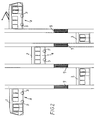
- 1 and 2 car bodies are referred to each other are pivotable.
- the car body 1 there are those that to the Ends of the rail vehicle are arranged, whereas those designated 2 Car body between the terminal car body 1 are arranged.
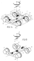
- Everyone who swiveling car body 1, 2 is on one in the illustrated embodiment cradle-free bogie 4 supported.
- the wheels 5 of the bogie can be driven, but also bogies with non-driven wheels 5 possible.
- the wheels 5 of the bogie 4 are on a cross bridge 6 of the Bogie frame esp. In swing 7 (Fig. 20, 24) stored.
- the Swing arm bearing is designated 22.
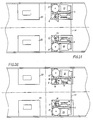
- To connect the cross bridge 6 with the Car body 1 or 2 is one designated 8 in the drawing as a whole Coupling device provided.
- a bridge 3 is arranged, which as a floating Car body is formed and each one of two in Vehicle longitudinal direction spaced joints 9 with the adjacent, each coupled to a bogie body 1, 2 is coupled.
- Fig. 1 the smallest basic unit of a rail vehicle is shown, the consists of a total of three car bodies, namely two terminal car bodies 1 and a car body 3 in between.
- the joints 9 are at one such basic unit as tannery joints and form a vertical Axis of rotation and can absorb moments about the lateral axis.
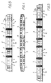
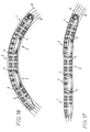
- the system is modular, so Rail vehicles consisting of five, seven and more car bodies are possible as illustrated in Figs. 3-5 and 16 and 17 in more detail.
- the joint 9 is in the drawings symbolically only by the bellows-like outer lining shown.
- the bogies 4 are designed with driven wheels 5, this is done the drive preferably via wheel hub motors 23, which as Three-phase asynchronous motors can be formed directly via planetary gear 24 on the wheels 5.
- wheel hub motors 23 which as Three-phase asynchronous motors can be formed directly via planetary gear 24 on the wheels 5.
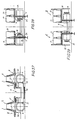
- This compact arrangement allows the drive directly under to accommodate adjacent wheel arch 20 (Fig. 27-29), the seats with their Leaning 21 dos-à-dos are arranged on each box 12 without podiums in Passenger compartment must be provided. This way it is possible to get one continuous low floor height of approx. 300 mm.
- the length of the bridge 3 at most equal to the length of the ones adjacent to it in the rail vehicle Bogies supported car body 1 or 2 if the requirement of a small envelope is set.
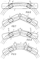
- Rail vehicles are different from road vehicles sufficient cross suspension necessary. Since this is primarily a Commuter vehicle in the lower speed class can Longitudinal linkage of the car body 1 on the bogie 4 to be rigid or very stiff Transfer braking or driving forces from the bogie 4 to the body 1. If a vehicle designed in this way (FIG. 9) now moves from the straight line into the curve, then the bogie 4 is immediately turned into the bow. The mass and that too Mass moment of inertia of the bogie 4 are small compared to that of the Car body 1. The heavier car body 1 therefore initially lingers in his Location. In the further course of time the elastic restoring forces Secondary suspension of the car body 1 of the bogie "pulled". The angle between bogie 4 and car body 1 is reduced again until in the case of pure circular arc travel, the angle reaches zero. The frequency and the The amplitude of this transient is dependent on the character of the secondary spring and their damping depends.
- Fig. 16 From Fig. 16 it can be seen that the rail vehicle according to the invention ideally fits a bow.
- the envelope is designated 33.
- the sum angle in the concept according to FIG. 10 is greater than with that according to Fig. 11. But that means that the passage width over the Bogies (low-floor vehicle) with an arrangement according to FIG. 10 may be smaller got to.
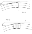
- a comparison of a cross-sprung two-axle (Fig. 13) with one torsionally elastic bogie according to Fig. 12 same transverse spring stiffness and The same wheel base shows that the run-up angle ⁇ between the running edge of the rail and the wheel plane of the two-axle vehicle according to FIG. 13 is higher than that of Bogie vehicle according to FIG. 12.
- connection of the car body to the bogie which can be seen in principle from Fig. 15.
- 14 shows another Execution also according to the principle.
- the connection is transverse and torsionally elastic by the flexicoil effect of the secondary suspension, which the car body on Bogie frame supported.
- the double arrow D indicates the Elasticity and the double arrow Q indicate the transverse elasticity.
- This can support by additional transverse spring elements, as shown in FIGS. 21, 22. Stops are provided to reduce the angle of rotation or the transverse movements limit.
- the coupling device between the car body 1 or 2 and the cross bridge 6 of the bogie frame has spring assemblies 10 and 11 according to FIGS. 23 and 24, whose axes extend essentially in the vehicle longitudinal direction and the each with one end against the car body 1 or 2 and with the other end are supported on the cross bridge 6. 23 and 24 of the car body 1 only the side member 15 is shown.
- the coupling between bogie 4 and Car body 1 is longitudinally rigid for the inclusion of brake and Accelerating forces, however - as will be explained later - also across and torsionally elastic.
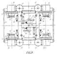
- 19 to 21 show arrangements in which the coupling device as Handlebar connection to achieve a longitudinally rigid connection of the Bogie frame is formed with the car body.
- the coupling device 8 is as Joint parallelogram formed.
- the bearings 12 of the handlebars forming the cranks 25 of the four-bar linkage are essentially symmetrical on the cross bridge 6 Longitudinal center plane arranged.
- the coupling of a two-armed lever 13 Joint parallelogram passes through a transverse slot 14 in the longitudinal member 15 and thus also in car bodies 1, 2.
- the two-armed lever 13 is connected via a vertical axis 16, the middle between the bearings 17 of the handlebars located in the two-armed lever 13 25 is arranged, connected to the longitudinal beam 15 of the car body 1 or 2.
- the suspension of body 1 or 2 against Bogie 4 is made using primary and secondary springs.
- the primary suspension is included formed as a rubber spring 26.
- the secondary suspension can be made of steel or rubber or be designed as an air spring. It is designated 27.
- a vertical damper 28 is parallel to each spring column of the secondary spring 27 arranged.
- At least one is between the rotating part 4 and the car body 1 Cross damper 29 arranged, which is also effective as a roll damper.
- Each The bogie is also provided with two magnetic rail brakes 30.
- the Cross bridge 6 is torsionally soft (X- or H-shaped) to avoid twists, those when driving on a ramp (camber in Vignolgleisen) or with track position errors occur, so that there are no significantly different wheel loads occurrence.
- the wheel hub motors 23 are supported by lane keeping rods 31 connected, which can also serve as a clearing house and exact compliance of the gauge in all operating conditions to ensure the related function of a wheelset shaft, yes in the bogies shown does not exist to meet.
- the two-armed lever 13 is in the middle in the this version H-shaped cross bridge 6 mounted.
- the in the camps 17 to the both ends of the two-armed lever 13 mounted handlebar 25 are at their from Stock 17 remote end stored on the car body.
- the handlebars 25 extend in opposite directions from the two-armed lever 13 away.
- additional Springs 40 are provided which are substantially transverse to the longitudinal direction of the vehicle are arranged.
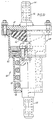
- FIG. 22 An embodiment of such a spring can be seen in FIG. 22.
- the Spring plates are designated 41, 42.
- the compression of the spring and thus also the transverse or rotational movement of the car body 1 with respect to the bogie 4 is delimited by a stop 43 which has a rubber buffer 44 cooperates.
- the rubber buffer 44 protrudes from the lid 47 into the interior of a Housing 48, the bottom of which is formed by one of the spring plates 41.
- the spring plate 41 guides a piston 49 passing through the spring, on which the stop 43, is preferably fastened by means of screws 50.
- the piston 49 has on its free, from the stop 43 remote end of a bearing bore 45 for connection to the Car body or the cross bridge, whereas the connection of the spring 40 to the Cross bridge or the car body by means of a (not shown) pin, which a bearing bore 46 in one connected to the cover 47 of the housing 48 Tab 51 penetrated.
- the two-armed lever 13 can, but need not, have spring assemblies 47 (Rubber / metal springs) to be supported on the cross bridge 6. These spring packs result in an additional torsion spring, which the Flexicoil effect of Secondary suspension 27 with a pure rotary movement of the bogie relative to Car body supports.
- the arrangement of the spring assemblies 47 is made so that when rotating - depending on the direction of rotation - only one spring assembly on pressure is claimed.
- the brake discs are referred to Normal gauge (Fig. 19, 20 and 23 - 26, 28) are within the gauge, at Narrow gauge (Fig. 29) are however arranged outside the gauge.
Landscapes
- Engineering & Computer Science (AREA)
- Mechanical Engineering (AREA)
- Transportation (AREA)
- Platform Screen Doors And Railroad Systems (AREA)
- Handcart (AREA)
- Automatic Cycles, And Cycles In General (AREA)
- Vehicle Body Suspensions (AREA)
- Vibration Prevention Devices (AREA)
- Machines For Laying And Maintaining Railways (AREA)
- Chain Conveyers (AREA)
Claims (10)
- Véhicule ferroviaire, comportant une pluralité de caisses de wagon, dont chacune est portée par des roues, un pont réalisé sous la forme d'une caisse de wagon flottante étant disposé entre deux caisses de wagon portées, chaque pont étant couplé aux caisses de wagon portées, voisines par l'intermédiaire de deux articulations espacées l'une de l'autre dans la direction longitudinale du véhicule, caractérisé en ce que les caisses de wagon portées, non réalisées sous forme de pont, sont portées chacune, au moyen de ressorts secondaires, sur un bâti tournant unique, bâti tournant dont le cadre (6) est relié à la caisse par un dispositif de couplage, les ressorts secondaires étant réalisés sous la forme de ressorts de type flexicoil, de manière que les caisses de wagon soient sustendues sur le cadre tournant (6), en bénéficiant d'une élasticité transversale et en rotation, et en ce qu'au cadre de bâti tournant (6) sont reliées des butées, réalisées en particulier sous forme de tampons (18), coopérant avec des contre-butées (19) montées sur la caisse de wagon (1, 2), afin de limiter le déplacement relatif se faisant sous l'influence de l'effet flexicoil de la suspension secondaire (27), déplacement se faisant entre le bâti tournant et les caisses (1, 2), et en ce que le dispositif de couplage relie au bâti tournant (4), avec une rigidité longitudinale ou de façon longitudinalement rigide, la caisse (1, 2) portée, non réalisée sous forme de pont.
- Véhicule ferroviaire selon la revendication 1, caractérisé en ce que le bâti tournant est réalisé sous forme de bâti tournant sans berceau.
- Véhicule ferroviaire selon la revendication 1 ou 2, caractérisé en ce que les roues sont chacune montées à rotation sur le cadre de bâti tournant, par l'intermédiaire d'une bielle oscillante.
- Véhicule ferroviaire selon l'une des revendications 1 à 3, caractérisé en ce que les roues du bâti tournant sont entraínées.
- Bâti tournant selon l'une des revendications 1 à 4, caractérisé en ce que le dispositif de couplage prévu pour assurer la liaison longitudinalement rigide de la caisse (1, 2) au bâti tournant présente des paquets de ressort (10, 11) dont les axes s'étendent sensiblement dans la direction longitudinale du véhicule et qui sont chacun soutenus, par une extrémité, sur la caisse (1, 2) et, par l'autre extrémité, sur le cadre de bâti. tournant (6) (figures 23, 24).
- Véhicule ferroviaire selon l'une des revendications 1 à 4, caractérisé en ce que le dispositif de couplage, destiné à assurer la liaison longitudinalement rigide de la caisse de wagon au cadre de bâti tournant (6), est réalisé, de manière connue en soi, sous forme de liaison par bielle, et en ce que cette liaison par bielle présente un levier à deux bras (13) qui est relié à pivotement, de préférence centralement à la caisse de wagon, en particulier à l'aide d'une poutre longitudinale (15) appartenant à la caisse de wagon (19, 20) ou bien à l'aide d'un pont transversal (6) reliant les deux poutres longitudinales du cadre de bâti tournant (4) (figure 21), dans la zone de chaque extrémité du levier à deux bras (13) s'engageant chaque fois une bielle (25) qui est reliée de manière articulée au pont transversal (6), par son extrémité opposée au levier à deux bras (13), ou, dans le cas ou le levier à deux bras agit sur le pont transversal (6), est relié à la caisse de wagon (1, 2) (figure 21).
- Véhicule ferroviaire selon la revendication 6, caractérisé en ce que le levier à deux bras (13) relié à pivotement à la poutre longitudinale (15) de la caisse traverse une fente transversale (14) ménagée dans la caisse de wagon et est relié de préférence, par l'intermédiaire d'un axe (16) vertical, à la caisse (1, 2) ou à sa poutre longitudinale (15) (figures 19, 20).
- Véhicule ferroviaire selon l'une des revendications 1 à 6, caractérisé en ce que, pour assister l'effet flexicoil des ressorts secondaires (27), sont prévus des ressorts additionnels (40) agissant sensiblement transversalement par rapport à la direction longitudinale du véhicule (figure 21).
- Véhicule ferroviaire selon l'une des revendications 1 à 8, caractérisé en ce que le levier à deux bras (13) est soutenu par des paquets de ressort (47) sur le cadre de bâti tournant, en particulier sur son pont transversal (6).
- Véhicule ferroviaire selon l'une des revendications 1 à 9, caractérisé en ce que l'espacement ü du centre du bâti tournant (4) (axe de pivotement vertical réel ou idéal du bâti tournant par rapport à la caisse de wagon), vis-à-vis de l'extrémité libre de la caisse (1) au point extrémité est de
Applications Claiming Priority (2)
| Application Number | Priority Date | Filing Date | Title |
|---|---|---|---|
| AT2514/91 | 1991-12-19 | ||
| AT0251491A AT403267B (de) | 1991-12-19 | 1991-12-19 | Schienenfahrzeug, insbesondere niederflurfahrzeug |
Publications (2)
| Publication Number | Publication Date |
|---|---|
| EP0548044A1 EP0548044A1 (fr) | 1993-06-23 |
| EP0548044B1 true EP0548044B1 (fr) | 1998-05-20 |
Family
ID=3535647
Family Applications (1)
| Application Number | Title | Priority Date | Filing Date |
|---|---|---|---|
| EP92890267A Expired - Lifetime EP0548044B1 (fr) | 1991-12-19 | 1992-12-18 | Véhicule ferroviaire |
Country Status (4)
| Country | Link |
|---|---|
| EP (1) | EP0548044B1 (fr) |
| AT (2) | AT403267B (fr) |
| DE (1) | DE59209335D1 (fr) |
| ES (1) | ES2118806T3 (fr) |
Cited By (6)
| Publication number | Priority date | Publication date | Assignee | Title |
|---|---|---|---|---|
| DE102013204483A1 (de) * | 2013-03-14 | 2014-09-18 | Bombardier Transportation Gmbh | Modulares Schienenfahrzeug mit unterschiedlich breiten Modulen |
| EP3109122A1 (fr) | 2015-06-23 | 2016-12-28 | Bombardier Transportation GmbH | Agencement et procede d'optimisation de l'enveloppante de vehicules a rails assembles par elements |
| EP3159236B1 (fr) | 2015-10-23 | 2019-03-20 | ALSTOM Transport Technologies | Véhicule ferroviaire comprenant au moins un bogie abaissé |
| WO2021058152A1 (fr) | 2019-09-27 | 2021-04-01 | Traktionssysteme Austria Gmbh | Machine de traction électrique non fermée |
| WO2021058151A1 (fr) | 2019-09-27 | 2021-04-01 | Traktionssysteme Austria Gmbh | Transmission par traction |
| EP3955435A1 (fr) | 2020-08-10 | 2022-02-16 | Traktionssysteme Austria GmbH | Moteur de traction électrique sans boitier |
Families Citing this family (17)
| Publication number | Priority date | Publication date | Assignee | Title |
|---|---|---|---|---|
| US4077563A (en) * | 1971-02-17 | 1978-03-07 | Karl Bo Lennart Lovqvist | Collecting device for refuse, dust etcetera |
| DE19650913A1 (de) * | 1996-12-07 | 1998-06-10 | Sab Wabco Bsi Verkehrstechnik | Angetriebene Losradachse |
| EP1065123B1 (fr) * | 1999-06-29 | 2003-08-27 | Mitsubishi Heavy Industries, Ltd. | Bogie de direction avec roues indépendantes |
| DE10010610A1 (de) * | 2000-03-03 | 2001-09-06 | Daimler Chrysler Ag | Schienenfahrzeug mit Wagenkasten und mindestens einem Fahrwerk |
| PL2366599T3 (pl) * | 2010-03-18 | 2014-03-31 | Stadler Rail Valencia S A | Szynowy pojazd, w szczególności niskopodłogowy szynowy pojazd |
| DE102011051634A1 (de) | 2011-07-07 | 2013-01-10 | Bombardier Transportation Gmbh | Konstruktionsverfahren zum Aufbau eines Schienenfahrzeugwagens, Verfahren zur Herstellung eines Schienenfahrzeugwagens, und Schienenfahrzeugfamilie |
| AT518820B1 (de) * | 2016-06-30 | 2018-07-15 | Siemens Ag Oesterreich | Elastisches Trägersystem für ein Schienenfahrzeug |
| EP3315799B2 (fr) † | 2016-10-26 | 2022-02-23 | GESIPA Blindniettechnik GmbH | Ecrou à rivet aveugle |
| CN107901993A (zh) * | 2017-12-18 | 2018-04-13 | 成都市新筑路桥机械股份有限公司 | 一种悬浮式车厢自动循迹的铰接客车 |
| EP4491487A3 (fr) | 2019-03-22 | 2025-05-14 | Stadler Rail AG | Train de roulement pour un véhicule ferroviaire et véhicule ferroviaire comprenant au moins un train de roulement, véhicule ferroviaire comprenant au moins un wagon de chemin de fer et procédé de réglage en hauteur d'une caisse d'un véhicule ferroviaire |
| CN110308724B (zh) | 2019-07-01 | 2022-06-03 | 阿波罗智能技术(北京)有限公司 | 自动驾驶控制方法、装置、车辆、存储介质及电子设备 |
| DE102019210814A1 (de) | 2019-07-22 | 2021-01-28 | Siemens Mobility GmbH | Schienenfahrzeug |
| CN112644549B (zh) * | 2019-10-10 | 2022-06-14 | 中车唐山机车车辆有限公司 | 转向架及轨道车辆 |
| FR3106557B1 (fr) * | 2020-01-23 | 2022-07-01 | Alstom Transp Tech | Bogie pour véhicule à roues indépendantes et véhicule associé |
| CN112298219B (zh) * | 2020-11-23 | 2024-12-31 | 湖南轨道技术应用研究中心有限公司 | 一种半悬浮式磁浮小火车运输系统 |
| CN115535020A (zh) * | 2021-06-30 | 2022-12-30 | 比亚迪股份有限公司 | 一种车厢间减振装置及列车 |
| CN114537461B (zh) * | 2022-02-14 | 2023-09-01 | 中铁工程装备集团隧道设备制造有限公司 | 一种大吨位隧道牵引车用转向架及大吨位隧道牵引车 |
Family Cites Families (11)
| Publication number | Priority date | Publication date | Assignee | Title |
|---|---|---|---|---|
| US660226A (en) * | 1899-12-02 | 1900-10-23 | Lewis Miller Smyth | Gate-latch. |
| CH153359A (de) * | 1931-01-22 | 1932-03-15 | Christoph & Unmack Aktiengesel | Gelenkwagen. |
| DE672163C (de) * | 1934-03-09 | 1939-02-22 | Curt Stedefeld Dipl Ing | Federung fuer Gleisfahrzeuge, deren Wagenkoerper gegenueber dem Laufwerk quer beweglich ist |
| DE708811C (de) * | 1936-08-18 | 1941-07-30 | Clemens A Voigt | Elastische Lagerung des Wagenkastens auf dem Drehgestell von Fahrzeugen, insbesondere Schienenfahrzeugen |
| BE639836A (fr) * | 1962-11-13 | |||
| FR1486355A (fr) * | 1966-07-11 | 1967-06-23 | Ganz Mavag Mozdony Vagon | Suspension de la caisse pour des véhicules de chemins de fer à bogies |
| DE2604769C3 (de) * | 1976-02-07 | 1981-07-23 | M.A.N. Maschinenfabrik Augsburg-Nürnberg AG, 8500 Nürnberg | Einrichtung zur Führung eines Schienenfahrzeug-Drehgestelles am Untergestell des Wagenkastens |
| DE2850878C2 (de) * | 1978-11-24 | 1983-09-15 | M.A.N. Maschinenfabrik Augsburg-Nürnberg AG, 8500 Nürnberg | Wiegebalkenloses Drehgestell mit Luftfederung für Schienenfahrzeuge |
| DE3205613C2 (de) * | 1982-02-17 | 1985-09-05 | M.A.N. Maschinenfabrik Augsburg-Nürnberg AG, 8500 Nürnberg | Gelenksteuerung von vierachsigen Schienenfahrzeugen, insbesondere Stadtbahnwagen |
| EP0271451A3 (fr) * | 1986-11-05 | 1988-09-14 | FIAT FERROVIARIA SAVIGLIANO S.p.A. | Bogie pour véhicules ferroviaires |
| GR1000703B (el) * | 1989-08-21 | 1992-10-08 | Schindler Waggon | Σκελετός δια όχημα με χαμηλό δάπεδο. |
-
1991
- 1991-12-19 AT AT0251491A patent/AT403267B/de not_active IP Right Cessation
-
1992
- 1992-12-18 DE DE59209335T patent/DE59209335D1/de not_active Expired - Lifetime
- 1992-12-18 EP EP92890267A patent/EP0548044B1/fr not_active Expired - Lifetime
- 1992-12-18 ES ES92890267T patent/ES2118806T3/es not_active Expired - Lifetime
- 1992-12-18 AT AT92890267T patent/ATE166298T1/de active
Cited By (12)
| Publication number | Priority date | Publication date | Assignee | Title |
|---|---|---|---|---|
| DE102013204483A1 (de) * | 2013-03-14 | 2014-09-18 | Bombardier Transportation Gmbh | Modulares Schienenfahrzeug mit unterschiedlich breiten Modulen |
| CN105143010A (zh) * | 2013-03-14 | 2015-12-09 | 庞巴迪运输有限公司 | 具有不同宽度模块的模块式轨道交通工具 |
| CN105143010B (zh) * | 2013-03-14 | 2019-07-09 | 庞巴迪运输有限公司 | 具有不同宽度模块的模块式轨道交通工具 |
| EP3109122A1 (fr) | 2015-06-23 | 2016-12-28 | Bombardier Transportation GmbH | Agencement et procede d'optimisation de l'enveloppante de vehicules a rails assembles par elements |
| DE102015211577A1 (de) | 2015-06-23 | 2016-12-29 | Bombardier Transportation Gmbh | Anordnung und Verfahren zur Optimierung der Hüllkurve von Schienenfahrzeugen in Gliederbauweise |
| EP3159236B1 (fr) | 2015-10-23 | 2019-03-20 | ALSTOM Transport Technologies | Véhicule ferroviaire comprenant au moins un bogie abaissé |
| EP3159236B2 (fr) † | 2015-10-23 | 2022-01-19 | ALSTOM Transport Technologies | Véhicule ferroviaire comprenant au moins un bogie abaissé |
| WO2021058152A1 (fr) | 2019-09-27 | 2021-04-01 | Traktionssysteme Austria Gmbh | Machine de traction électrique non fermée |
| WO2021058151A1 (fr) | 2019-09-27 | 2021-04-01 | Traktionssysteme Austria Gmbh | Transmission par traction |
| US11658541B2 (en) | 2019-09-27 | 2023-05-23 | Traktionssysteme Austria Gmbh | Unenclosed electric traction machine |
| EP3955435A1 (fr) | 2020-08-10 | 2022-02-16 | Traktionssysteme Austria GmbH | Moteur de traction électrique sans boitier |
| WO2022033943A1 (fr) | 2020-08-10 | 2022-02-17 | Traktionssysteme Austria Gmbh | Machine de traction électrique non close |
Also Published As
| Publication number | Publication date |
|---|---|
| AT403267B (de) | 1997-12-29 |
| ATE166298T1 (de) | 1998-06-15 |
| ATA251491A (de) | 1997-05-15 |
| DE59209335D1 (de) | 1998-06-25 |
| EP0548044A1 (fr) | 1993-06-23 |
| ES2118806T3 (es) | 1998-10-01 |
Similar Documents
| Publication | Publication Date | Title |
|---|---|---|
| EP0548044A1 (fr) | Véhicule ferroviaire | |
| DE2940892A1 (de) | Verfahren zum umruesten eines eisenbahn-fahrgestells mit einem mechanismus zur radsatzsteuerung | |
| EP0567950A1 (fr) | Véhicule ferroviaire | |
| DE102014212360A1 (de) | Gelenkfahrzeug mit einem querverschiebbaren Gelenk | |
| EP0649782B1 (fr) | Véhicule ferroviaire et train de roulement pour un tel véhicule | |
| EP0282738A1 (fr) | Bogie à essieu unique avec des roues folles pour véhicules ferroviaires | |
| EP0168578B1 (fr) | Train de roues pour véhicules ferroviaires | |
| EP0580995B1 (fr) | Système de véhicules guidés consistant d'au moins deux véhicules avec des trains de roulement commandés avec des trains de roues uniques | |
| DE19507021C2 (de) | Fahrwerk für Eisenbahnfahrzeuge | |
| EP0838386B1 (fr) | Véhicule ferroviaire avec au moins un train de roulement et train de roulement pour un tel véhicule | |
| EP0855326B1 (fr) | Train de roulement avec deux essieux pour système de transport sur rails. | |
| DE1010092B (de) | Laufwerksanordnung fuer einen Schienengliederzug | |
| EP0388999A2 (fr) | Dispositif mécanique pour supporter des véhicules ferroviaires | |
| DE4142028C2 (de) | Laufwerk für Schienenfahrzeuge | |
| EP0658465B1 (fr) | Bogie auto-directeur à trois essieux pour un véhicule ferroviaire | |
| EP0410407B1 (fr) | Sous-châssis de roulement pour un véhicule ou un bogie ferroviaires | |
| EP0930210B1 (fr) | Train de roulement pour véhicules ferroviaires et véhicule ferroviaire avec au moins un tel train de roulement | |
| EP0678436B1 (fr) | Bogie auto-directeur à trois essieux pour un véhicule ferroviaire | |
| AT398557B (de) | Fahrwerk für ein schienenfahrzeug, insbesondere niederflurfahrzeug | |
| EP1674367B1 (fr) | Dispositif pour la liaison articulée de deux caisses d'un véhicule ferroviaire à sections multiples | |
| EP3109121B1 (fr) | Bati tournant pour vehicules ferroviaire a plusieurs articulations et vehicules ferroviaire a plusieurs articulations | |
| DE3135074C2 (de) | Drehgestell für Schienenfahrzeuge | |
| DE9409044U1 (de) | Niederflur-Gelenktriebwagen, insbesondere für den Personenverkehr auf innerstädtischen Schienennetzen | |
| DE4422109C2 (de) | Kuppelbare Fahrwerkanordnung zum Tragen und Querneigen eines Wagenkastens | |
| DE947617C (de) | Fahrgestell fuer Eisenbahngliederzuege |
Legal Events
| Date | Code | Title | Description |
|---|---|---|---|
| PUAI | Public reference made under article 153(3) epc to a published international application that has entered the european phase |
Free format text: ORIGINAL CODE: 0009012 |
|
| AK | Designated contracting states |
Kind code of ref document: A1 Designated state(s): AT BE CH DE ES FR GB GR IT LI NL PT SE |
|
| 17P | Request for examination filed |
Effective date: 19931217 |
|
| 17Q | First examination report despatched |
Effective date: 19941209 |
|
| GRAG | Despatch of communication of intention to grant |
Free format text: ORIGINAL CODE: EPIDOS AGRA |
|
| GRAG | Despatch of communication of intention to grant |
Free format text: ORIGINAL CODE: EPIDOS AGRA |
|
| GRAH | Despatch of communication of intention to grant a patent |
Free format text: ORIGINAL CODE: EPIDOS IGRA |
|
| GRAH | Despatch of communication of intention to grant a patent |
Free format text: ORIGINAL CODE: EPIDOS IGRA |
|
| GRAA | (expected) grant |
Free format text: ORIGINAL CODE: 0009210 |
|
| AK | Designated contracting states |
Kind code of ref document: B1 Designated state(s): AT BE CH DE ES FR GB GR IT LI NL PT SE |
|
| PG25 | Lapsed in a contracting state [announced via postgrant information from national office to epo] |
Ref country code: GR Free format text: LAPSE BECAUSE OF NON-PAYMENT OF DUE FEES Effective date: 19980520 |
|
| REF | Corresponds to: |
Ref document number: 166298 Country of ref document: AT Date of ref document: 19980615 Kind code of ref document: T |
|
| REG | Reference to a national code |
Ref country code: CH Ref legal event code: EP |
|
| REF | Corresponds to: |
Ref document number: 59209335 Country of ref document: DE Date of ref document: 19980625 |
|
| ITF | It: translation for a ep patent filed | ||
| PG25 | Lapsed in a contracting state [announced via postgrant information from national office to epo] |
Ref country code: PT Free format text: LAPSE BECAUSE OF FAILURE TO SUBMIT A TRANSLATION OF THE DESCRIPTION OR TO PAY THE FEE WITHIN THE PRESCRIBED TIME-LIMIT Effective date: 19980820 |
|
| GBT | Gb: translation of ep patent filed (gb section 77(6)(a)/1977) |
Effective date: 19980814 |
|
| REG | Reference to a national code |
Ref country code: CH Ref legal event code: NV Representative=s name: LUCHS & PARTNER PATENTANWAELTE |
|
| REG | Reference to a national code |
Ref country code: ES Ref legal event code: FG2A Ref document number: 2118806 Country of ref document: ES Kind code of ref document: T3 |
|
| ET | Fr: translation filed | ||
| PLBE | No opposition filed within time limit |
Free format text: ORIGINAL CODE: 0009261 |
|
| 26N | No opposition filed | ||
| REG | Reference to a national code |
Ref country code: GB Ref legal event code: IF02 |
|
| REG | Reference to a national code |
Ref country code: FR Ref legal event code: TP |
|
| PGFP | Annual fee paid to national office [announced via postgrant information from national office to epo] |
Ref country code: AT Payment date: 20101214 Year of fee payment: 19 |
|
| PGFP | Annual fee paid to national office [announced via postgrant information from national office to epo] |
Ref country code: GB Payment date: 20101221 Year of fee payment: 19 |
|
| PGFP | Annual fee paid to national office [announced via postgrant information from national office to epo] |
Ref country code: SE Payment date: 20111223 Year of fee payment: 20 Ref country code: CH Payment date: 20111227 Year of fee payment: 20 Ref country code: NL Payment date: 20111228 Year of fee payment: 20 Ref country code: FR Payment date: 20120105 Year of fee payment: 20 Ref country code: ES Payment date: 20111227 Year of fee payment: 20 |
|
| PGFP | Annual fee paid to national office [announced via postgrant information from national office to epo] |
Ref country code: BE Payment date: 20111229 Year of fee payment: 20 |
|
| PGFP | Annual fee paid to national office [announced via postgrant information from national office to epo] |
Ref country code: DE Payment date: 20111222 Year of fee payment: 20 |
|
| PGFP | Annual fee paid to national office [announced via postgrant information from national office to epo] |
Ref country code: IT Payment date: 20111229 Year of fee payment: 20 |
|
| REG | Reference to a national code |
Ref country code: DE Ref legal event code: R071 Ref document number: 59209335 Country of ref document: DE |
|
| REG | Reference to a national code |
Ref country code: DE Ref legal event code: R071 Ref document number: 59209335 Country of ref document: DE |
|
| REG | Reference to a national code |
Ref country code: NL Ref legal event code: V4 Effective date: 20121218 |
|
| BE20 | Be: patent expired |
Owner name: *BOMBARDIER-WIEN SCHIENENFAHRZEUGE A.G. Effective date: 20121218 |
|
| REG | Reference to a national code |
Ref country code: CH Ref legal event code: PL |
|
| REG | Reference to a national code |
Ref country code: GB Ref legal event code: PE20 Expiry date: 20121217 |
|
| REG | Reference to a national code |
Ref country code: SE Ref legal event code: EUG |
|
| PG25 | Lapsed in a contracting state [announced via postgrant information from national office to epo] |
Ref country code: GB Free format text: LAPSE BECAUSE OF EXPIRATION OF PROTECTION Effective date: 20121217 |
|
| REG | Reference to a national code |
Ref country code: AT Ref legal event code: MK07 Ref document number: 166298 Country of ref document: AT Kind code of ref document: T Effective date: 20121218 |
|
| REG | Reference to a national code |
Ref country code: ES Ref legal event code: FD2A Effective date: 20140827 |
|
| PG25 | Lapsed in a contracting state [announced via postgrant information from national office to epo] |
Ref country code: ES Free format text: LAPSE BECAUSE OF EXPIRATION OF PROTECTION Effective date: 20121219 |