EP0548512B1 - Dispositif accumulateur d'un bobinoir pour supports individuels - Google Patents
Dispositif accumulateur d'un bobinoir pour supports individuels Download PDFInfo
- Publication number
- EP0548512B1 EP0548512B1 EP92118844A EP92118844A EP0548512B1 EP 0548512 B1 EP0548512 B1 EP 0548512B1 EP 92118844 A EP92118844 A EP 92118844A EP 92118844 A EP92118844 A EP 92118844A EP 0548512 B1 EP0548512 B1 EP 0548512B1
- Authority
- EP
- European Patent Office
- Prior art keywords
- storage
- path
- caddies
- transport
- paths
- Prior art date
- Legal status (The legal status is an assumption and is not a legal conclusion. Google has not performed a legal analysis and makes no representation as to the accuracy of the status listed.)
- Expired - Lifetime
Links
- 238000004804 winding Methods 0.000 title claims description 40
- 239000000969 carrier Substances 0.000 title description 4
- 238000011144 upstream manufacturing Methods 0.000 claims description 2
- 238000012544 monitoring process Methods 0.000 claims 3
- 230000032258 transport Effects 0.000 description 55
- 230000015654 memory Effects 0.000 description 16
- 238000009825 accumulation Methods 0.000 description 11
- 230000010485 coping Effects 0.000 description 4
- 238000002360 preparation method Methods 0.000 description 3
- 238000007726 management method Methods 0.000 description 2
- 238000004140 cleaning Methods 0.000 description 1
- 238000007599 discharging Methods 0.000 description 1
- 230000006870 function Effects 0.000 description 1
- 230000001105 regulatory effect Effects 0.000 description 1
- 238000009987 spinning Methods 0.000 description 1
Images

Classifications
-
- D—TEXTILES; PAPER
- D01—NATURAL OR MAN-MADE THREADS OR FIBRES; SPINNING
- D01H—SPINNING OR TWISTING
- D01H9/00—Arrangements for replacing or removing bobbins, cores, receptacles, or completed packages at paying-out or take-up stations ; Combination of spinning-winding machine
- D01H9/18—Arrangements for replacing or removing bobbins, cores, receptacles, or completed packages at paying-out or take-up stations ; Combination of spinning-winding machine for supplying bobbins, cores, receptacles, or completed packages to, or transporting from, paying-out or take-up stations ; Arrangements to prevent unwinding of roving from roving bobbins
- D01H9/187—Arrangements for replacing or removing bobbins, cores, receptacles, or completed packages at paying-out or take-up stations ; Combination of spinning-winding machine for supplying bobbins, cores, receptacles, or completed packages to, or transporting from, paying-out or take-up stations ; Arrangements to prevent unwinding of roving from roving bobbins on individual supports, e.g. pallets
Definitions
- the invention relates to a storage device of a winding machine with the features of the preamble of the first claim.
- Such a transport cycle for caddy's is described, for example, in JP-A 52-25 139.
- a particular advantage is the avoidance of damage to the winding of the cops and, in particular, the possibility of individual handling of the individual cops or caddy-bearing bobbins.
- one or more memories are provided in the transport loop in order to adapt to the fluctuating reception of cops in the processing device to provide. It is either an empty case memory or a head memory.
- a generic storage device of a winding machine for mutually independent caddies has become known.
- the caddies circulate within the transport system of the winding machine.
- the storage device is connected on the input and output side to this transport system and has a cop attachment position.
- the empty tubes coming from the winding machine are first pulled off by hand from the caddies and new heads to be unwound are put on in the bobbin winder position.
- a similar device is described in the unpublished DE 40 29 894 A1.
- a storage device is arranged parallel to the return transport path leading the payout spool sleeves and residual spools and is integrated in such a way that there is a closed circuit for independent individual carriers for the payout spools.
- the individual carriers arranged in the memory can be supplied with new cops with the aid of a loading device.
- the loading device has shaft sections which, when opened, permit the free passage of the payout spools and, when closed, form a safe guidance of the payout spools when they are placed on the individual carriers.
- the known storage devices have only relatively few storage locations for the caddy's, which means that the operator has to return to the machine at short intervals in order to attach new heads to the caddy's and ultimately to avoid that empty caddy's or caddy's with empty tubes are fed to the winding units.
- the arrangement according to the invention of independent storage sections with common transport sections offers the possibility that the cop attachment position can be arranged at a selectable location in the edge region of the transport sections, regardless of the storage capacity.
- the arrangement of the cop attachment position at an easily accessible location ensures, in particular, problem-free handling of the cops by the operating personnel.
- the arrangement of the bobbin plug-on position in the region of a transport path which extends from the output side of the storage bins to the bobbin delivery path of the winding machine and a branching of an overflow path downstream of the bobbin plug-on position allow relatively simple administration of the entire storage device.
- the storage device according to the invention allows the same storage sections to be used both for caddies with cops and for empty caddies.
- the coping position in the edge region of the transport path extending between the common transport path connected on the output side to the storage paths and the spool delivery path of the winding machine. Such an arrangement is particularly accessible for the operating personnel.
- a plurality of storage positions can be provided downstream of the cop attachment position in the region of the transport path and the overflow path.
- the respective filling status of the storage positions can be easily monitored by sensors.
- the entry and exit of Caddy's in groups can be easily implemented with the help of stoppers.
- the arrangement of the overflow section can be varied several times within the scope of the invention. It depends on the space available and, for example, the desired storage capacity of the same. In connection with this, it is also possible to connect the line leading from the sleeve return path to the storage lines to one of the two ends of the common transport line connected on the input side to the storage lines.
- the storage sections are advantageously filled and emptied successively from section to section, advantageously empty caddies and caddies equipped with cops being interrupted by an empty section. Due to the respective stowage sections, it is possible to fill and empty entire stowage sections. This reduces the control effort. In addition, control-related empty caddy's and caddy's with cops are easier to separate.
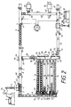
- the storage device forms a transport loop for the caddy's 1, which is connected on the input side to the sleeve return path 57 of the winding machine and on the output side to the bobbin delivery path 5 of the winding machine, which is otherwise not shown.
- a known so-called residual switch 61 actuates a switch 62 so that it only allows caddy's 1 with empty sleeves 3 to pass, only caddy's 1 with empty sleeves 3 reach a sleeve pulling device 59 on the sleeve return path 57.
- the sleeves 3 are removed from the caddy's 1 and placed in a sleeve container 60. The sleeve pulling device 59 then only leaves empty caddy's 1.
- the subsequent transport path 58 opens into a common transport path 15 connected on the input side to storage paths 9 to 14. Points 35 to 39 are arranged on this common transport path 15 and can be controlled by a memory control device 74. They allow Caddy's 1 to be fed into the respective storage path.
- the storage sections 9 to 14, like the other transport sections, are formed by transport channels, within which the caddies 1 are taken along by friction by means of transport belts (not shown separately). There is no need for a more detailed description of the fact that such transport routes are already known from JP-A 52-25 139 mentioned at the beginning.
- the representation of the drive devices for the conveyor belts of the individual transport sections has been dispensed with throughout.
- the direction of transport of the upper run of the conveyor belts, which inevitably corresponds to the direction of transport of the Caddy's 1, is illustrated by directional arrows.
- Sensors 28 to 33 are arranged at the respective input of the storage sections 9 to 14, which determine the passage of the caddies 1 and report them to the storage control device 74.
- stoppers 16 to 21 Arranged at the output end of the storage sections 9 to 14 are stoppers 16 to 21 which, controlled by the storage control device 74, retain the stored caddies 1 or permit the storage section to be emptied.
- Adjacent to these stoppers 16 to 21 are further sensors 22 to 27, which both determine the arrival of the first caddy 1 in a previously empty storage section and the exit of the last caddy after the storage has been emptied. The latter occurs either through a longer pause after a caddy 1 has passed or by counting the caddy passing the sensor, the number of which is known per storage path.
- the storage sections 9 to 14 open into the common transport section 8 arranged on the output side, which merges into a transport section 8 ', which in turn leads to the coil supply path 5.
- a cop attachment position 43 is provided on the section 8 ′, at which, as can be seen in FIG. 2, an operator 76 attaches cops 4 to the caddies 1, which they remove from a cop container 44.
- a second storage section 7 is provided downstream of the cop plug-on position 43 and the stopper 46 is arranged at the front end thereof. This accumulation section 7 can be monitored with regard to its filling state by means of sensors 48 and 49. In addition, these sensors 48 and 49, which are connected to the memory control device 74, can also be used to count the caddies 1 transported past with cops 4.
- a first accumulation section 6 is provided, which has a stopper 47 at its front end for accumulating the caddy's 1 and is monitored for its filling state by a sensor 50 at its rear end. From this first accumulation section 6, the instantaneous coping requirement of the winding machine is covered.
- a residual button 61 is connected to a switch 62 arranged downstream. If the rest button 61 has recognized a larger, that is to say further processable winding residue, the switch 62 is pivoted into the sleeve return path 57, so that the caddy 1, which the Restkops carries, is redirected into the link 69, which leads to the coil feed path 5.
- the switch 64 is also actuated, which deflects this caddy 1 from the connecting section 69 to a branch path 68, on which a so-called cone preparation device 66 is arranged, which is particularly suitable for locating thread ends on residual cops.
- the switch 63 is actuated in addition to the switch 62, which deflects this caddy 1 into the branch path 67, on which a tube cleaning device 65 is arranged. Further explanations of this winding machine-specific circuit are not necessary since such a system is already described in DE-A 39 19 542.
- the remaining button 61 has recognized a remaining cop or an ejected cop, the thread start of which could not be fed to the winding unit, instead of leading it through the switch 62 into the connecting section 69, on this to be transported past.
- the sleeve pulling device 59 must also be activated so that it does not remove this remaining cop or ejected cop from the caddy 1 carrying it. This caddy 1 with remaining cops or ejected cops with full wrapping is then transported into the same storage path in which it would be transported as an empty caddy.
- This remaining bobbin or ejected bobbin is then fed to the operator at the bobbin mounting position 43, which, instead of putting on a new bobbin, can search for the thread end and deposit it in such a way that the normal bobbin preparation device arranged in the winding machine can release this thread end and deposit it accordingly. If necessary, it is also possible to use the counting the caddy's as described, to track the path of the same and to feed it to a very specific storage section which must have free storage spaces for this.
- the empty caddy's 1, in which the plug-on mandrel 2 can be seen are fed from the sleeve pulling device 59 past an opening 53 to an overflow section 52 past a storage section 73.
- a stopper 71 which also has a connection to the memory control device 74, is arranged at the front end of this storage section 73.
- An adjacently arranged sensor 72 also monitors the passage of the caddy's at this point, while another sensor 72 ′ can monitor the filling status of this storage section 73 with respect to the empty caddy's 1.
- this empty storage section which separates the two storage sections from one another, always moves from one end of the storage device to the other end.
- the storage section 11 has just been freed from the caddies 1 carrying the heads 4, which are fed to the second storage section 7.
- This storage path 11 will next form the empty storage path, while the switch 37 on the input side Connected common transport route 15 is set so that this storage route can accommodate empty caddy's 1 delivered from the storage route 73.
- the switch 37 then remains open until it has been determined by counting the empty caddies 1 that have entered the storage section 12 that the storage section 12 is filled.
- the switch 37 is then moved into the same position as the switches 38 and 39 on the storage sections 13 and 14, which have already been opened.
- the storage section 9 only one leading edge 34 is required, since the caddies 1 arriving there must be fed to this storage section in any case.
- a guide edge 40 is also provided for deflecting the caddies from the transport path 58 into the common transport path 15 connected on the input side.
- a sensor 51 Downstream of the stopper 47 arranged at the front end of the accumulation section 6, a sensor 51 is arranged, with the aid of which the cops 4 fed to the winding machine, which have been released by the stopper 47, are counted.
- This sensor 51 like the sensor 70 arranged on the sleeve return path 57, is connected to the storage control device 74, which represents the central control unit for the storage device and, if appropriate, for the entire winding machine.
- the cops are also allocated here according to the requirements of the winding machine. As is generally the case, this need is met at the exit of Empty tubes from the winding machine measured by sensor 70.
- the memory control device 74 controls the opening of the stopper 47 after the passage of one or more sleeves 3 on the sleeve return path 57. If the sensor 51 has determined a corresponding number of cops, the stopper 47 is closed again. If, due to the time delay, a larger number of cops 4 have passed sensor 51 when empty tubes have been ejected, this number is also taken into account in the memory control device, which subtracts this from the number of tubes then ejected. In this way, the number of cops and tubes in the direct winding machine cycle is always kept constant.
- Guide profiles 41 and 42 are likewise arranged on the common transport path 8 connected on the output side, which guide the caddies in each case into their intended transport direction.
- an overflow section 52 is provided, which can be controlled by means of a switch 56.
- This overflow section 52 has a stop 54 at its downstream end, so that it itself can also function as a storage section. The filling of this overflow section 52 can be monitored by means of the sensor 55 which is arranged at its entry end and which is likewise connected to the memory control device 74.
- the stopper 54 can be opened when the storage section 73 is empty. This requires that before the stopper 71 has been opened in order to remove the pent-up empty caddy's 1 from the storage section 73. Furthermore, the stopper 71 'must also be kept closed so that no empty caddy's mix with the caddies 1 fed from the overflow section 52 with cops 4.
- the management of this storage section 73 is carried out in a simple manner with the aid of sensors 72 and 72 ', by means of which it can always be determined whether there are still caddies in this storage section 73.
- the phase of the coping is shown.
- empty caddies 1 are fed to the plug-on position 43 from the storage path 13.
- the operator To initiate this slip-on phase, the operator must issue a corresponding command to the memory controller 74, which then switches to the cop plug-on mode.
- the operator 76 can also actuate a stopper 45 at the cops attachment position 43, by means of which the caddies to be equipped with cops are stopped at this point.
- this stopper 45 there is also the possibility of automatically opening this stopper 45 in cycles after the start-up of the cop attachment mode, so that the operator 76 only has to deal with attaching the cops 4 to the caddies provided.
- the Kopsaufsteckposition covers a limited area of the transport route 8 ', so that the Operator can always reach the cop holder 44 when attaching the cop.
- the run-off time in the winding unit is relatively long in relation to small bobbins.
- the time span for attaching a cop 4 to a caddy 1 is thus considerably less than the cycle time for the cop request from the winding machine.
- This makes it possible for the storage sections to be completely filled with fresh cops (except for the remaining storage section, at the end of the plugging cycle of the storage section 14) within the scope of a coping cycle. In this way, with a corresponding storage capacity, there is a relatively long period of time within which the operator does not have to visit the winding machine for attaching cops.
- the first storage section 6 is just being filled. Since the sensor 50 at the end of this first storage section 6 does not yet detect that a caddy 1 with cops 4 is positioned next to it over a longer period of time, the caddies 1 with freshly attached cops 4 are first fed to this first storage section 6. If the sensor 50 then recognizes that this first accumulation section 6 is filled, the stopper 46 is first closed by the memory control device 74, after which the second accumulation section 7 is filled until the sensor 48 also recognizes its filling state at the end of this accumulation section. Thereupon the stopper 46 is opened and at the same time the switch 56 is switched over, so that the caddies 1 released by the stopper 46 are fed to the overflow section 85.
- this overflow section 85 is monitored by means of a sensor 47 which detects the caddies 1 entering the overflow section 85 with cops 4 counts.
- a stopper 86 is arranged at the downstream end of this overflow section 85, as a result of which the overflow section can also be used as a, but here relatively short, storage section.
- switches 79 to 84 can also be switched to two different functional positions at the inputs of the storage sections 9 to 14, which are demonstrated by the switches 81 and 83.
- the switch 81 is set such that caddy's 1, which come from the overflow section 85, can be transported into the storage section 11 when the conveyor belt of the transport section 77 transports in the direction of its leading edge 78 or in the direction of the transport section 58.
- the switch 83 is effective in the opposite direction of transport when empty caddies are to be transferred from the storage section 73 into the storage section 13.
- the reversing drive of the conveyor belt of the conveyor line 77 is also controlled by the memory control device 74.
- the transport of the caddy's 1 must be monitored, which are counted at the corresponding sensors. In principle, it must be ensured that the caddies 1 located on the transport path 77 must have entered the storage path intended for them before the transport direction of the conveyor belt of the transport path 77 changes.
- a storage section 73 is provided, the filling state of which can be monitored by means of a sensor 75. However, it is not a further stopper is required since the overflow section 85 does not open into the transport section 58.
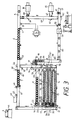
- FIG. 3 shows a further variant of the design of the storage device according to the invention.
- the transport path 89 which adjoins the sleeve return path 57, opens into an overflow path 93 which merges into the common transport path 93 'connected on the input side.
- this web guide which has been changed compared to FIG. 2, it is not necessary to provide a reversing drive for this common transport route 93 '.
- the switches 97 to 101 can be designed so that they have only one working position.
- the overflow section 93 has a stop 94 in front of the confluence of the transport path 89 in order to avoid mixing of the caddies 4 carrying caddies 1 with the empty caddies 1.
- a sensor 95 is arranged on the branch of the overflow section 93 from the transport track 8 ′ and is used to monitor the caddies 1 entering the overflow section 93. Also, as already described in the other exemplary embodiments, there is a switch 56 at this input, which lies between the two storage sections 6 and 7.
- the storage phase shown in FIG. 3 shows a state in which it will soon be necessary for the operator to go to the head attachment position 43 in order to replenish the memory with caddies 1 carrying the heads 4.
- the two accumulation sections 6 and 7 are still filled, which the two sensors 48 and 50 recognize.
- the last storage path is the Storage section 9, only partially filled with cops 4 carrying caddy's 1.
- the storage control device 74 which manages the entire storage device, triggers a signal in order to call the operator. This time should not be chosen much later in order to ensure the uninterrupted supply of cops to the winding machine.
- a stopper 92 and a sensor 91 are provided at the end of the transport path 89.
- This stopper 92 is located at the beginning of a storage section 90 on the transport path 89.
- the filling state of this storage section 90 is possible here by means of a sensor 88 which is arranged at a distance from the stopper 92 which corresponds to the desired length of the storage section 90.
- caddy's 1 with cops 4 are released from the first storage section 6 at the request of the winding machine.
- the sensor 50 requests 7 new cops from the second accumulation section 7 via the memory control device 74 in order to keep the first accumulation section 6 constantly filled. If the sensor arranged in the vicinity of the stop 46 then detects that the second storage section 7 is empty, the refilling of this second storage section 7 is effected by opening the stop 16 at the outlet of the storage section 9.
- the refilling of empty caddy's 1 from the storage section 90 takes place only when the storage section 9 is completely emptied in order to secure the respective empty storage section. This means that the storage path 9 is empty before the new heads 4 are plugged in, while the storage path 14 is empty after the heads are plugged in.
- the empty storage path always "moves" from one end to the other end of the storage.
Landscapes
- Engineering & Computer Science (AREA)
- Mechanical Engineering (AREA)
- Textile Engineering (AREA)
- Replacing, Conveying, And Pick-Finding For Filamentary Materials (AREA)
Claims (17)
- Dispositif de stockage d'un bobinoir pour des supports (1) indépendants les uns des autres, qui circulent à l'intérieur d'un système de transport du bobinoir et, au moyen de mandrins à embrocher (2), transportent des bobines (4) et des tubes de bobines (3) en position debout, le dispositif de stockage étant raccordé, à l'entrée et à la sortie, au système de transport, et un poste (43) d'embrochage de bobines étant présent dans la boucle de transport qui est alors formée, caractérisé en ce que :- le dispositif de stockage possède plusieurs sections de stockage (9 à 14) indépendantes l'une de l'autre, qui reçoivent des supports triés, avec bobines et sans bobines,- les sections de stockage sont raccordées à l'entrée et à la sortie à des sections de transport communes de chaque côté (8, 15; 77; 93'),- des moyens de commutation (16 à 21, 35 à 39; 79 à 84; 97 à 101), servant à faire entrer et sortir les supports sur commande, sont placés sur les sections de stockage,- un dispositif de commande de stockage (74) peut sélectionner les sections de stockage à l'entrée et à la sortie,- la section de transport commune (8) raccordée à la sortie mène, par l'intermédiaire d'une section de transport (8'), à un parcours d'amenée des bobines (5) du bobinoir,- le poste d'embrochage des bobines (43) est installé en un endroit bien accessible au voisinage de la section de transport (8) commune, raccordée côté sortie aux sections de stockage (9 à 14) ou sur la section de transport (8') qui va de ladite section de transport (8) au parcours d'amenée des bobines (5), et- en aval du poste d'embrochage des bobines (43), une section de trop-plein (52; 85; 93) part en dérivation et mène à la section de transport commune (15; 77; 93') raccordée côté entrée aux sections de stockage (9 à 14).
- Dispositif de stockage suivant la revendication 1, caractérisé en ce que le poste (43) d'embrochage de bobines se trouve dans la partie marginale de la section de transport (8') qui s'étend de la section de transport (8) commune raccordée aux sections de stockage du côté sortie jusqu'au parcours (5) d'amenée des bobines.
- Dispositif de stockage suivant la revendication 1 ou 2, caractérisé en ce que des capteurs (22 à 27, 28 à 33) sont prévus aux deux extrémités des sections de stockage (9 à 14) pour surveiller leur taux de remplissage.
- Dispositif de stockage suivant l'une quelconque des revendications 1 à 3, caractérisé en ce qu'un dispositif d'arrêt (45) est prévu près du poste d'embrochage de bobines et peut être actionné par l'opérateur ou par le dispositif de commande de stockage (74).
- Dispositif de stockage suivant l'une quelconque des revendications 1 à 4, caractérisé en ce qu'un premier tronçon de stockage (6) est disposé sur la section (8') conduisant au parcours d'amenée des bobines, en aval par rapport à la bifurcation de la section de trop-plein (52; 85; 93).
- Dispositif de stockage suivant la revendication 5, caractérisé en ce qu'un deuxième tronçon de stockage (7) se trouve, en amont de la bifurcation de la section de trop-plein, sur la section (8') conduisant au parcours d'amenée des bobines, et en ce que des capteurs (48, 50) de surveillance du taux de remplissage sont placés dans les deux tronçons de stockage.
- Dispositif de stockage suivant la revendication 6, caractérisé en ce que dans le dispositif de commande de stockage (74) est prévu un circuit qui produit le remplissage du premier tronçon de stockage (6) à partir du deuxième tronçon de stockage (7) et, si les deux tronçons de stockage sont entièrement remplis, manoeuvre un aiguillage (56) à l'entrée de la section de trop-plein (52; 85; 93), aiguillage qui transfère les supports du deuxième tronçon de stockage dans la section de trop-plein.
- Dispositif de stockage suivant l'une quelconque des revendications 1 à 7, caractérisé en ce que la section de trop-plein (52; 85; 93) possède un capteur (55; 87; 95) pour surveiller leur taux de remplissage, capteur qui est relié à un circuit du dispositif de commande de stockage (74) pour ouvrir un dispositif d'arrêt (54; 86; 94) placé à l'extrémité aval de la section de trop-plein.
- Dispositif de stockage suivant l'une quelconque des revendications 1 à 8, caractérisé en ce qu'un circuit du dispositif de commande de stockage (74) commande les moyens de commutation servant à faire passer dans les sections de stockage les supports arrivant de la section de trop-plein de telle façon que les sections de stockage soient remplies successivement de supports (1) portant des bobines (4).
- Dispositif de stockage suivant l'une quelconque des revendications 1 à 9, caractérisé en ce que la section de trop-plein (85) débouche directement dans la section de transport (77) commune raccordée du côté entrée aux sections de stockage.
- Dispositif de stockage suivant la revendication 10, caractérisé en ce que la section de transport commune (77) raccordée du côté entrée aux sections de stockage est réalisée de telle façon qu'elle puisse transporter les supports dans les deux sens suite à des ordres de commande.
- Dispositif de stockage suivant la revendication 10, caractérisé en ce qu'une section de transport (89) raccordée au parcours de retour des tubes de bobines à la suite d'un dispositif (59) de retrait des tubes de bobines est raccordée à la section de trop-plein (93) à la même extrémité de la section de transport commune (93').
- Dispositif de stockage suivant l'une quelconque des revendications 1 à 9, caractérisé en ce que la section de trop-plein (52) débouche dans la section de transport (58) raccordée au parcours (57) de retour des tubes de bobines à la suite d'un dispositif (59) de retrait des tubes de bobines.
- Dispositif de stockage suivant l'une quelconque des revendications 1 à 13, caractérisé en ce qu'un tronçon d'encombrement (73; 90), surveillé par des capteurs, est prévu dans la section de transport (58; 89) raccordée au parcours (57) de retour des tubes de bobines à la suite d'un dispositif (59) de retrait des tubes de bobines.
- Dispositif de stockage suivant la revendication 14, caractérisé en ce que, pour constituer le tronçon d'encombrement (73; 90), un dispositif d'arrêt (71; 92) est prévu et peut être actionné par le circuit du dispositif de commande de stockage (74) qui commande le dispositif d'arrêt (54; 86; 94) placé à l'extrémité aval de la section de trop-plein (52; 85; 93), le circuit étant réalisé de telle façon qu'il ouvre toujours un seul des deux dispositifs d'arrêt.
- Dispositif de stockage suivant la revendication 15, caractérisé en ce que le dispositif de commande de stockage (74) qui commande les moyens de commutation servant à introduire les supports dans les sections de stockage est réalisé de telle façon que les sections de stockage soient remplies successivement de supports vides (1), mais dans l'ordre de remplissage inverse de celui avec des supports pourvus de bobines (4).
- Dispositif de stockage suivant la revendication 11 et l'une quelconque des revendications 14 à 16, caractérisé en ce que le circuit du dispositif de commande de stockage (74) qui actionne tour à tour l'un des dispositifs d'arrêt (71, 86) situés dans la section de trop-plein (85) et dans la section de transport (58) raccordée au parcours de retour des tubes de bobines commande toujours le sens d'entraînement des organes de transport de la section de transport commune (77) raccordée côté entrée aux sections de stockage, de telle façon que le transport des supports (1) se fasse à partir de l'extrémité de la section de transport où le dispositif d'arrêt voisin est ouvert.
Applications Claiming Priority (2)
| Application Number | Priority Date | Filing Date | Title |
|---|---|---|---|
| DE4142621A DE4142621A1 (de) | 1991-12-21 | 1991-12-21 | Speichereinrichtung einer spulmaschine fuer voneinander unabhaengige caddy's |
| DE4142621 | 1991-12-21 |
Publications (2)
| Publication Number | Publication Date |
|---|---|
| EP0548512A1 EP0548512A1 (fr) | 1993-06-30 |
| EP0548512B1 true EP0548512B1 (fr) | 1994-10-19 |
Family
ID=6447915
Family Applications (1)
| Application Number | Title | Priority Date | Filing Date |
|---|---|---|---|
| EP92118844A Expired - Lifetime EP0548512B1 (fr) | 1991-12-21 | 1992-11-04 | Dispositif accumulateur d'un bobinoir pour supports individuels |
Country Status (4)
| Country | Link |
|---|---|
| US (1) | US5308001A (fr) |
| EP (1) | EP0548512B1 (fr) |
| JP (1) | JPH05278949A (fr) |
| DE (2) | DE4142621A1 (fr) |
Families Citing this family (17)
| Publication number | Priority date | Publication date | Assignee | Title |
|---|---|---|---|---|
| IT1261670B (it) * | 1992-05-22 | 1996-05-29 | Murata Machinery Ltd | Sistema di alimentazione di bobine. |
| DE4339964A1 (de) * | 1993-11-24 | 1995-06-01 | Schlafhorst & Co W | Spulenträgertransportsystem für eine Kreuzspulen herstellende Textilmaschine |
| US6622847B2 (en) | 1996-03-15 | 2003-09-23 | Rapistan Systems Advertising Corp. | Compact article unscrambler |
| US5918723A (en) * | 1996-03-15 | 1999-07-06 | Mannesmann Dematic Rapistan Corp. | Compact article singulation conveyor |
| US6269933B1 (en) | 1996-03-15 | 2001-08-07 | Mannesmann Dematic Rapistan Corp. | Compact article unscrambler |
| IT1298984B1 (it) * | 1998-03-31 | 2000-02-07 | Savio Macchine Tessili Spa | Sistema perfezionato di movimentazione delle spole e dei tubetti per le roccatrici automatiche |
| US6311822B1 (en) * | 1998-04-22 | 2001-11-06 | Jervis B. Webb Company | Method and apparatus for high speed article processing |
| DE102007013175A1 (de) * | 2007-03-20 | 2008-09-25 | Knapp Logistik Automation Gmbh | Verfahren und Kommissionierautomat zum Befüllen eines Auftragsbehälters |
| DE102009041239A1 (de) * | 2009-09-11 | 2011-03-24 | Krones Ag | Vorrichtung und Verfahren zum Bilden einer Gebindesequenz |
| PE20131406A1 (es) * | 2010-12-06 | 2013-12-16 | Fleetwoodgoldcowyard Inc | Acumulador de transportador para controlar el flujo de articulos que se estan transportando |
| FR3004172B1 (fr) * | 2012-11-16 | 2017-12-22 | Sidel Participations | Dispositif et procede d'accumulation et de transfert |
| FR3003551B1 (fr) * | 2013-03-25 | 2015-04-24 | Sidel Participations | Procede de transfert d'au moins un objet depuis une surface de convoyage vers une surface de reception, et systeme comprenant des moyens pour la mise en oeuvre d'un tel procede |
| PL3021987T3 (pl) * | 2013-07-19 | 2023-08-28 | Compac Technologies Limited | Urządzenie do przenoszenia artykułów |
| US9533837B2 (en) * | 2014-12-18 | 2017-01-03 | Compac Technologies Limited | Article carrier apparatus |
| US9688482B2 (en) * | 2015-03-17 | 2017-06-27 | Illinois Tool Works Inc. | Apparatus for buffering the flow of articles |
| US9896271B1 (en) | 2016-09-29 | 2018-02-20 | Barry-Wehmiller Container Systems, Inc. | Conveyor accumulator for controlling the flow of articles being conveyed |
| US10336555B1 (en) * | 2018-12-11 | 2019-07-02 | King Saud University | Baggage handling and delivery system |
Family Cites Families (12)
| Publication number | Priority date | Publication date | Assignee | Title |
|---|---|---|---|---|
| US3122231A (en) * | 1960-06-21 | 1964-02-25 | Cutler Hammer Inc | Memory type storage conveyor system |
| US3118549A (en) * | 1960-08-30 | 1964-01-21 | Cutler Hammer Inc | Storage conveyor system |
| GB1170660A (en) * | 1967-07-01 | 1969-11-12 | Giddings & Lewis Fraser Ltd | Magazine for Supplying Bobbins to a Winding Machine |
| JPS5859167A (ja) * | 1981-09-25 | 1983-04-08 | Murata Mach Ltd | 管糸搬送システム |
| US4576341A (en) * | 1982-03-08 | 1986-03-18 | Murata Kikai Kabushiki Kaisha | Cop transporting systems for an automatic winder |
| JPS59223667A (ja) * | 1983-05-03 | 1984-12-15 | Murata Mach Ltd | パツケ−ジ搬送装置 |
| JPS6397583A (ja) * | 1986-10-14 | 1988-04-28 | Murata Mach Ltd | ボビン搬送システム |
| US4940127A (en) * | 1986-12-12 | 1990-07-10 | Murata Kikai Kabushiki Kaisha | Wound yarn package transporting system |
| DE3919526C2 (de) * | 1989-06-15 | 1999-11-18 | Schlafhorst & Co W | Automatische Spulmaschine mit einem Transportsystem, in dem Kopse und Hülsen aufrechtstehend auf Paletten aufgesetzt sind |
| DE3919542A1 (de) * | 1989-06-15 | 1990-12-20 | Schlafhorst & Co W | Automatische spulmaschine mit einem kops- und huelsentransportsystem mit mehreren transportschleifen |
| DE4019475A1 (de) * | 1990-06-19 | 1992-01-02 | Schlafhorst & Co W | Spulmaschine mit an einer bedienstelle etwa in tischhoehe angeordneten spulenaufnahmemitteln |
| DE4029894A1 (de) * | 1990-09-21 | 1992-03-26 | Schlafhorst & Co W | Spulmaschine, die von hand mit ablaufspulen beschickt werden kann |
-
1991
- 1991-12-21 DE DE4142621A patent/DE4142621A1/de not_active Withdrawn
-
1992
- 1992-11-04 EP EP92118844A patent/EP0548512B1/fr not_active Expired - Lifetime
- 1992-11-04 DE DE59200658T patent/DE59200658D1/de not_active Expired - Fee Related
- 1992-12-21 JP JP4340189A patent/JPH05278949A/ja active Pending
- 1992-12-21 US US07/994,110 patent/US5308001A/en not_active Expired - Fee Related
Also Published As
| Publication number | Publication date |
|---|---|
| DE59200658D1 (de) | 1994-11-24 |
| EP0548512A1 (fr) | 1993-06-30 |
| JPH05278949A (ja) | 1993-10-26 |
| US5308001A (en) | 1994-05-03 |
| DE4142621A1 (de) | 1993-06-24 |
Similar Documents
| Publication | Publication Date | Title |
|---|---|---|
| EP0402630B1 (fr) | Bobinoir automatique avec un système de transport de canettes et de tubes avec plusieurs boucles de transport | |
| DE3341895C2 (fr) | ||
| DE3235442C2 (de) | Vorrichtung zum Zuliefern von Kopsen | |
| EP0548512A1 (fr) | Dispositif accumulateur d'un bobinoir pour supports individuels | |
| DE3213253A1 (de) | Vorrichtung zum beliefern eines spulautomaten mit kopsen | |
| DE3308171A1 (de) | Kopstransportsystem fuer einen spulautomaten | |
| DE4309582A1 (de) | Automatische Spulmaschine, die mehrere, teilweise gemeinsame Transportwege aufweisende Transportschleifen für Textilspulen besitzt | |
| EP0427990B1 (fr) | Dispositif pour exécuter automatiquement le raccordement de fil ainsi que le changement de cannettes, constitués par une suite fixe d'opérations à un poste de bobinage d'une machine de bobinage | |
| EP1006069B1 (fr) | Bobinoir automatique à fil croisé et procédé de fonctionnement d'un bobinoir automatique à fil croisé | |
| DE3244378A1 (de) | Vorrichtung zum ablegen und einbehalten des fadenendes in der spulenhuelse eines von einer kopsvorbereitungsstation an ein transportmittel weitergegebenen spinnkopses | |
| DE3245325C2 (fr) | ||
| DE4317266C2 (de) | Verfahren zum Steuern der Zuführung von Spinnspulen zu einer Spulmaschine | |
| DE4032617A1 (de) | Vorrichtung zum automatischen durchfuehren des eine feste schrittfolge aufweisenden fadenverbindens sowie kopswechsels an einer spulstelle einer spulmaschine | |
| DE4211112C2 (de) | Vorrichtung zum Beliefern eines Spulautomaten mit aufrechtstehend auf Spulentransportteller aufgesteckten Kopsen | |
| DE3422134C2 (fr) | ||
| DE3432184C2 (fr) | ||
| DE3337348A1 (de) | Kopsliefervorrichtung fuer eine automatische wickelmaschine | |
| CH666245A5 (de) | Spinn- und spulaggregat. | |
| DE4233819C2 (de) | Verfahren zum Betreiben einer automatischen Spulmaschine bei Partiewechsel | |
| EP0569772B1 (fr) | Procédé et dispositif pour la fabrication d'un nombre donné de bobines pleines croisées sur une machine de bobinage à spires croisées | |
| DE4029894A1 (de) | Spulmaschine, die von hand mit ablaufspulen beschickt werden kann | |
| EP0402731B1 (fr) | Bobinoir automatique avec un transporteur pour cannettes suivant une boucle fermée | |
| DE3504883C2 (fr) | ||
| DE3734820C2 (fr) | ||
| EP0462479B1 (fr) | Machine de bobinage dont le poste de travail est équipé de moyens de manipulation à peu près au niveau d'une table |
Legal Events
| Date | Code | Title | Description |
|---|---|---|---|
| PUAI | Public reference made under article 153(3) epc to a published international application that has entered the european phase |
Free format text: ORIGINAL CODE: 0009012 |
|
| AK | Designated contracting states |
Kind code of ref document: A1 Designated state(s): BE CH DE IT LI |
|
| 17P | Request for examination filed |
Effective date: 19930818 |
|
| 17Q | First examination report despatched |
Effective date: 19931124 |
|
| ITF | It: translation for a ep patent filed | ||
| GRAA | (expected) grant |
Free format text: ORIGINAL CODE: 0009210 |
|
| AK | Designated contracting states |
Kind code of ref document: B1 Designated state(s): BE CH DE IT LI |
|
| REF | Corresponds to: |
Ref document number: 59200658 Country of ref document: DE Date of ref document: 19941124 |
|
| PLBE | No opposition filed within time limit |
Free format text: ORIGINAL CODE: 0009261 |
|
| STAA | Information on the status of an ep patent application or granted ep patent |
Free format text: STATUS: NO OPPOSITION FILED WITHIN TIME LIMIT |
|
| 26N | No opposition filed | ||
| PGFP | Annual fee paid to national office [announced via postgrant information from national office to epo] |
Ref country code: BE Payment date: 19961120 Year of fee payment: 5 |
|
| PGFP | Annual fee paid to national office [announced via postgrant information from national office to epo] |
Ref country code: DE Payment date: 19961213 Year of fee payment: 5 |
|
| PGFP | Annual fee paid to national office [announced via postgrant information from national office to epo] |
Ref country code: CH Payment date: 19961219 Year of fee payment: 5 |
|
| PG25 | Lapsed in a contracting state [announced via postgrant information from national office to epo] |
Ref country code: LI Free format text: LAPSE BECAUSE OF NON-PAYMENT OF DUE FEES Effective date: 19971130 Ref country code: CH Free format text: LAPSE BECAUSE OF NON-PAYMENT OF DUE FEES Effective date: 19971130 Ref country code: BE Free format text: LAPSE BECAUSE OF NON-PAYMENT OF DUE FEES Effective date: 19971130 |
|
| BERE | Be: lapsed |
Owner name: W. SCHLAFHORST A.G. & CO. Effective date: 19971130 |
|
| REG | Reference to a national code |
Ref country code: CH Ref legal event code: PL |
|
| PG25 | Lapsed in a contracting state [announced via postgrant information from national office to epo] |
Ref country code: DE Free format text: LAPSE BECAUSE OF NON-PAYMENT OF DUE FEES Effective date: 19980801 |
|
| PG25 | Lapsed in a contracting state [announced via postgrant information from national office to epo] |
Ref country code: IT Free format text: LAPSE BECAUSE OF NON-PAYMENT OF DUE FEES;WARNING: LAPSES OF ITALIAN PATENTS WITH EFFECTIVE DATE BEFORE 2007 MAY HAVE OCCURRED AT ANY TIME BEFORE 2007. THE CORRECT EFFECTIVE DATE MAY BE DIFFERENT FROM THE ONE RECORDED. Effective date: 20051104 |