EP0550721B2 - Vorrichtung zum anbringen einer isolierschicht an der oberfläche eines gegenstandes - Google Patents
Vorrichtung zum anbringen einer isolierschicht an der oberfläche eines gegenstandes Download PDFInfo
- Publication number
- EP0550721B2 EP0550721B2 EP92915255A EP92915255A EP0550721B2 EP 0550721 B2 EP0550721 B2 EP 0550721B2 EP 92915255 A EP92915255 A EP 92915255A EP 92915255 A EP92915255 A EP 92915255A EP 0550721 B2 EP0550721 B2 EP 0550721B2
- Authority
- EP
- European Patent Office
- Prior art keywords
- nozzle
- spray nozzle
- nozzles
- conduit
- fibres
- Prior art date
- Legal status (The legal status is an assumption and is not a legal conclusion. Google has not performed a legal analysis and makes no representation as to the accuracy of the status listed.)
- Expired - Lifetime
Links
- 239000000835 fiber Substances 0.000 claims abstract description 55
- 239000007788 liquid Substances 0.000 claims abstract description 27
- 239000011230 binding agent Substances 0.000 claims abstract description 17
- 238000009736 wetting Methods 0.000 claims abstract description 9
- XLYOFNOQVPJJNP-UHFFFAOYSA-N water Substances O XLYOFNOQVPJJNP-UHFFFAOYSA-N 0.000 claims abstract description 8
- 238000009413 insulation Methods 0.000 claims abstract description 7
- 238000001035 drying Methods 0.000 claims abstract description 6
- 229910010272 inorganic material Inorganic materials 0.000 claims abstract description 5
- 239000011147 inorganic material Substances 0.000 claims abstract description 5
- 239000000203 mixture Substances 0.000 claims abstract description 3
- 239000007921 spray Substances 0.000 claims abstract 13
- 239000003365 glass fiber Substances 0.000 claims description 7
- BPQQTUXANYXVAA-UHFFFAOYSA-N Orthosilicate Chemical compound [O-][Si]([O-])([O-])[O-] BPQQTUXANYXVAA-UHFFFAOYSA-N 0.000 claims description 3
- 229910052500 inorganic mineral Inorganic materials 0.000 claims 1
- 239000011707 mineral Substances 0.000 claims 1
- 238000000034 method Methods 0.000 abstract description 7
- 239000010410 layer Substances 0.000 abstract 2
- 239000002344 surface layer Substances 0.000 abstract 1
- 239000011491 glass wool Substances 0.000 description 5
- 238000009826 distribution Methods 0.000 description 4
- 238000004519 manufacturing process Methods 0.000 description 4
- 239000000428 dust Substances 0.000 description 3
- ISWSIDIOOBJBQZ-UHFFFAOYSA-N Phenol Chemical compound OC1=CC=CC=C1 ISWSIDIOOBJBQZ-UHFFFAOYSA-N 0.000 description 2
- 239000011248 coating agent Substances 0.000 description 2
- 238000000576 coating method Methods 0.000 description 2
- 239000007789 gas Substances 0.000 description 2
- 239000011810 insulating material Substances 0.000 description 2
- 239000004810 polytetrafluoroethylene Substances 0.000 description 2
- 229920001343 polytetrafluoroethylene Polymers 0.000 description 2
- 230000005855 radiation Effects 0.000 description 2
- QTBSBXVTEAMEQO-UHFFFAOYSA-M Acetate Chemical compound CC([O-])=O QTBSBXVTEAMEQO-UHFFFAOYSA-M 0.000 description 1
- 201000004624 Dermatitis Diseases 0.000 description 1
- 206010040880 Skin irritation Diseases 0.000 description 1
- 229910000831 Steel Inorganic materials 0.000 description 1
- 239000000853 adhesive Substances 0.000 description 1
- 230000001070 adhesive effect Effects 0.000 description 1
- 239000007864 aqueous solution Substances 0.000 description 1
- 208000010668 atopic eczema Diseases 0.000 description 1
- 238000007664 blowing Methods 0.000 description 1
- 230000001419 dependent effect Effects 0.000 description 1
- 230000000694 effects Effects 0.000 description 1
- 239000011490 mineral wool Substances 0.000 description 1
- 238000012986 modification Methods 0.000 description 1
- 230000004048 modification Effects 0.000 description 1
- 230000002093 peripheral effect Effects 0.000 description 1
- 238000003825 pressing Methods 0.000 description 1
- 238000005086 pumping Methods 0.000 description 1
- 238000007789 sealing Methods 0.000 description 1
- 238000004062 sedimentation Methods 0.000 description 1
- 229910052710 silicon Inorganic materials 0.000 description 1
- 239000010703 silicon Substances 0.000 description 1
- 230000036556 skin irritation Effects 0.000 description 1
- 231100000475 skin irritation Toxicity 0.000 description 1
- 238000005507 spraying Methods 0.000 description 1
- 239000010959 steel Substances 0.000 description 1
- 238000004381 surface treatment Methods 0.000 description 1
Images

Classifications
-
- D—TEXTILES; PAPER
- D04—BRAIDING; LACE-MAKING; KNITTING; TRIMMINGS; NON-WOVEN FABRICS
- D04H—MAKING TEXTILE FABRICS, e.g. FROM FIBRES OR FILAMENTARY MATERIAL; FABRICS MADE BY SUCH PROCESSES OR APPARATUS, e.g. FELTS, NON-WOVEN FABRICS; COTTON-WOOL; WADDING ; NON-WOVEN FABRICS FROM STAPLE FIBRES, FILAMENTS OR YARNS, BONDED WITH AT LEAST ONE WEB-LIKE MATERIAL DURING THEIR CONSOLIDATION
- D04H1/00—Non-woven fabrics formed wholly or mainly of staple fibres or like relatively short fibres
- D04H1/40—Non-woven fabrics formed wholly or mainly of staple fibres or like relatively short fibres from fleeces or layers composed of fibres without existing or potential cohesive properties
- D04H1/42—Non-woven fabrics formed wholly or mainly of staple fibres or like relatively short fibres from fleeces or layers composed of fibres without existing or potential cohesive properties characterised by the use of certain kinds of fibres insofar as this use has no preponderant influence on the consolidation of the fleece
- D04H1/4209—Inorganic fibres
- D04H1/4218—Glass fibres
-
- B—PERFORMING OPERATIONS; TRANSPORTING
- B29—WORKING OF PLASTICS; WORKING OF SUBSTANCES IN A PLASTIC STATE IN GENERAL
- B29C—SHAPING OR JOINING OF PLASTICS; SHAPING OF MATERIAL IN A PLASTIC STATE, NOT OTHERWISE PROVIDED FOR; AFTER-TREATMENT OF THE SHAPED PRODUCTS, e.g. REPAIRING
- B29C70/00—Shaping composites, i.e. plastics material comprising reinforcements, fillers or preformed parts, e.g. inserts
- B29C70/04—Shaping composites, i.e. plastics material comprising reinforcements, fillers or preformed parts, e.g. inserts comprising reinforcements only, e.g. self-reinforcing plastics
- B29C70/28—Shaping operations therefor
- B29C70/30—Shaping by lay-up, i.e. applying fibres, tape or broadsheet on a mould, former or core; Shaping by spray-up, i.e. spraying of fibres on a mould, former or core
- B29C70/305—Spray-up of reinforcing fibres with or without matrix to form a non-coherent mat in or on a mould
-
- B—PERFORMING OPERATIONS; TRANSPORTING
- B29—WORKING OF PLASTICS; WORKING OF SUBSTANCES IN A PLASTIC STATE IN GENERAL
- B29C—SHAPING OR JOINING OF PLASTICS; SHAPING OF MATERIAL IN A PLASTIC STATE, NOT OTHERWISE PROVIDED FOR; AFTER-TREATMENT OF THE SHAPED PRODUCTS, e.g. REPAIRING
- B29C70/00—Shaping composites, i.e. plastics material comprising reinforcements, fillers or preformed parts, e.g. inserts
- B29C70/68—Shaping composites, i.e. plastics material comprising reinforcements, fillers or preformed parts, e.g. inserts by incorporating or moulding on preformed parts, e.g. inserts or layers, e.g. foam blocks
- B29C70/86—Incorporated in coherent impregnated reinforcing layers, e.g. by winding
-
- D—TEXTILES; PAPER
- D04—BRAIDING; LACE-MAKING; KNITTING; TRIMMINGS; NON-WOVEN FABRICS
- D04H—MAKING TEXTILE FABRICS, e.g. FROM FIBRES OR FILAMENTARY MATERIAL; FABRICS MADE BY SUCH PROCESSES OR APPARATUS, e.g. FELTS, NON-WOVEN FABRICS; COTTON-WOOL; WADDING ; NON-WOVEN FABRICS FROM STAPLE FIBRES, FILAMENTS OR YARNS, BONDED WITH AT LEAST ONE WEB-LIKE MATERIAL DURING THEIR CONSOLIDATION
- D04H1/00—Non-woven fabrics formed wholly or mainly of staple fibres or like relatively short fibres
- D04H1/40—Non-woven fabrics formed wholly or mainly of staple fibres or like relatively short fibres from fleeces or layers composed of fibres without existing or potential cohesive properties
- D04H1/58—Non-woven fabrics formed wholly or mainly of staple fibres or like relatively short fibres from fleeces or layers composed of fibres without existing or potential cohesive properties by applying, incorporating or activating chemical or thermoplastic bonding agents, e.g. adhesives
- D04H1/64—Non-woven fabrics formed wholly or mainly of staple fibres or like relatively short fibres from fleeces or layers composed of fibres without existing or potential cohesive properties by applying, incorporating or activating chemical or thermoplastic bonding agents, e.g. adhesives the bonding agent being applied in wet state, e.g. chemical agents in dispersions or solutions
- D04H1/655—Non-woven fabrics formed wholly or mainly of staple fibres or like relatively short fibres from fleeces or layers composed of fibres without existing or potential cohesive properties by applying, incorporating or activating chemical or thermoplastic bonding agents, e.g. adhesives the bonding agent being applied in wet state, e.g. chemical agents in dispersions or solutions characterised by the apparatus for applying bonding agents
-
- D—TEXTILES; PAPER
- D04—BRAIDING; LACE-MAKING; KNITTING; TRIMMINGS; NON-WOVEN FABRICS
- D04H—MAKING TEXTILE FABRICS, e.g. FROM FIBRES OR FILAMENTARY MATERIAL; FABRICS MADE BY SUCH PROCESSES OR APPARATUS, e.g. FELTS, NON-WOVEN FABRICS; COTTON-WOOL; WADDING ; NON-WOVEN FABRICS FROM STAPLE FIBRES, FILAMENTS OR YARNS, BONDED WITH AT LEAST ONE WEB-LIKE MATERIAL DURING THEIR CONSOLIDATION
- D04H1/00—Non-woven fabrics formed wholly or mainly of staple fibres or like relatively short fibres
- D04H1/70—Non-woven fabrics formed wholly or mainly of staple fibres or like relatively short fibres characterised by the method of forming fleeces or layers, e.g. reorientation of fibres
- D04H1/72—Non-woven fabrics formed wholly or mainly of staple fibres or like relatively short fibres characterised by the method of forming fleeces or layers, e.g. reorientation of fibres the fibres being randomly arranged
- D04H1/732—Non-woven fabrics formed wholly or mainly of staple fibres or like relatively short fibres characterised by the method of forming fleeces or layers, e.g. reorientation of fibres the fibres being randomly arranged by fluid current, e.g. air-lay
-
- D—TEXTILES; PAPER
- D04—BRAIDING; LACE-MAKING; KNITTING; TRIMMINGS; NON-WOVEN FABRICS
- D04H—MAKING TEXTILE FABRICS, e.g. FROM FIBRES OR FILAMENTARY MATERIAL; FABRICS MADE BY SUCH PROCESSES OR APPARATUS, e.g. FELTS, NON-WOVEN FABRICS; COTTON-WOOL; WADDING ; NON-WOVEN FABRICS FROM STAPLE FIBRES, FILAMENTS OR YARNS, BONDED WITH AT LEAST ONE WEB-LIKE MATERIAL DURING THEIR CONSOLIDATION
- D04H1/00—Non-woven fabrics formed wholly or mainly of staple fibres or like relatively short fibres
- D04H1/70—Non-woven fabrics formed wholly or mainly of staple fibres or like relatively short fibres characterised by the method of forming fleeces or layers, e.g. reorientation of fibres
- D04H1/72—Non-woven fabrics formed wholly or mainly of staple fibres or like relatively short fibres characterised by the method of forming fleeces or layers, e.g. reorientation of fibres the fibres being randomly arranged
- D04H1/736—Non-woven fabrics formed wholly or mainly of staple fibres or like relatively short fibres characterised by the method of forming fleeces or layers, e.g. reorientation of fibres the fibres being randomly arranged characterised by the apparatus for arranging fibres
-
- F—MECHANICAL ENGINEERING; LIGHTING; HEATING; WEAPONS; BLASTING
- F16—ENGINEERING ELEMENTS AND UNITS; GENERAL MEASURES FOR PRODUCING AND MAINTAINING EFFECTIVE FUNCTIONING OF MACHINES OR INSTALLATIONS; THERMAL INSULATION IN GENERAL
- F16L—PIPES; JOINTS OR FITTINGS FOR PIPES; SUPPORTS FOR PIPES, CABLES OR PROTECTIVE TUBING; MEANS FOR THERMAL INSULATION IN GENERAL
- F16L59/00—Thermal insulation in general
- F16L59/04—Arrangements using dry fillers, e.g. using slag wool
-
- F—MECHANICAL ENGINEERING; LIGHTING; HEATING; WEAPONS; BLASTING
- F24—HEATING; RANGES; VENTILATING
- F24C—DOMESTIC STOVES OR RANGES ; DETAILS OF DOMESTIC STOVES OR RANGES, OF GENERAL APPLICATION
- F24C15/00—Details
- F24C15/34—Elements and arrangements for heat storage or insulation
-
- B—PERFORMING OPERATIONS; TRANSPORTING
- B29—WORKING OF PLASTICS; WORKING OF SUBSTANCES IN A PLASTIC STATE IN GENERAL
- B29K—INDEXING SCHEME ASSOCIATED WITH SUBCLASSES B29B, B29C OR B29D, RELATING TO MOULDING MATERIALS OR TO MATERIALS FOR MOULDS, REINFORCEMENTS, FILLERS OR PREFORMED PARTS, e.g. INSERTS
- B29K2995/00—Properties of moulding materials, reinforcements, fillers, preformed parts or moulds
- B29K2995/0012—Properties of moulding materials, reinforcements, fillers, preformed parts or moulds having particular thermal properties
- B29K2995/0015—Insulating
Definitions
- the present invention refers to a device for applying an insulating layer onto a surface of an object.
- the oven cavity In connection with oven cavities used in ranges or built-in ovens the oven cavity has to be provided with a heat insulation surrounding said cavity which prevents the heat energy supplied to the oven from unnecessarily leaking out to the environment and, at the same time, assures that surrounding parts do not reach such high temperatures at which there is a risk of fire or other damage to occur.
- a heat insulation of the kind referred to have the shape of mats and plates of glass-wool or mineral wool cut out and secured to the outer surfaces of the oven by means of steel straps or the like or, at the rear side of the oven, by means of an adhesive.
- the most common insulating material is glass-wool which consists of glass fibres kept together by a phenol-based binder.
- these mats or plates of glass-fibre have to be cut out and otherwise handled in a way creating glass fibre dust which appears in large quantities.
- This disadvantage is strengthened by the use of tools driven by compressed air.
- the manual handling itself of the glass-wool mats and plates involves the risk of skin irritations and eczema to develop.
- Another drawback is the creation of nasty-smelling gases emitted from the phenol containing binder of the heat insulation when the finished oven is used.
- DE-A-28 15 616 discloses a method of applying an insulating layer to a surface of an object such that fibres of an inorganic material are sprayed onto the surface under simultaneous wetting of the fibres with a binder so that the fibres stick to the surface.
- the embodiment to be described refers to the application of a heat insulating layer to the outside of an oven cavity intended to be mounted in a domestic range.
- the oven cavity may constitute a separate unit in the shape of a built-in oven.
- the application of the insulating layer is carried out in an automatic work station of a suitable design. In Fig. 1 the design of such work station is schematically shown.
- a method is being used according to which fibres of a inorganic heat insulating material are sprayed onto the external surface of the oven cavity under simultaneous wetting of the fibres with an aqueous binder causing the fibres to stick to the cavity.
- the fibres are glass-wool fibres and the binder is of the silicate type and in the example described the binder is EKA Thorsil®, having 14 percentage by weight of Silicon and 86 percentage by weight of water.
- This drying process can take place in a convection oven at temperatures below 600 °C or by means of infrared radiation elements.
- an acetate-based binder can be applied to the insulating layer in order to prevent or substantially limit the creation of dust during the handling of the oven cavity and, in addition, to improve the mechanical strenght of the layer.
- the application can take place prior to drying if the drying temperatures do not exceed about 200 °C.
- An example of such binder is NATIONAL®, ML 7224 which is to be applied as an aqueous solution.
- Fig. 1 an establishment is shown in which an insulating layer of the kind referred to can be applied to the outside of an oven cavity designated by 10.
- the establishment is built up around a handling robot 11 which collects an oven cavity from a collecting station 12 and brings it to a work station 13 where the application is to take place. After the application the robot moves the cavity to another collecting station 14 for further transport within the production establishment.
- the fibre to be applied to the oven cavity is obtained from a fibre tearing machine 15 of a kind known per se.
- Afibre bale 16 is inserted in the machine to be fed by a feeding means 17 towards rollers 18, 19 of a shape so as to convert the bale into a stream of fibre bundles which, by means of air, are blown towards the inlet of a hose 20 the outlet end of which opens into an application nozzle 21.
- two ejectors one of which, designated 22, disposed at the inlet of the hose and another one, designated 23, disposed at the outlet end of the hose. The function of the ejectors will be described more in detail in the following.
- the application nozzle 21 emits a stream of fibres which is directed towards the oven cavity.
- the fibres are wetted with liquid from nozzles 24 disposed around the outlet opening of said nozzle.
- the liquid is provided from a liquid system comprising a container 25 and a pump 26.
- the liquid consists of a slicate binder and water and to prevent sedimentation when the nozzle is not operating the liquid is circulated in the system and, in addition, a stirrer 27 is provided in the container 25 which is activated during the circulation process.
- a pumping device can also be used which continuously adds water.
- the robot 11 is arranged to move the different sides of the cavity past the application nozzle, which is fixed. In doing so, the gripping tool of the robot performs the different movements in synchronism with the way of working of the nozzle so that layers of a predetermined thickness are applied to the sides of the cavity.
- the application process is controlled by a control unit 28 programmed to perform a number of different programs to be selected by a keyboard 29 or the like.
- the figure contains a hydraulic pump 30 which operates the fibre tearing machine 15 and a unit 31 comprising valves and regulators for air and liquid to the ejectors 22 and 23 and to the liquid nozzles 24, respectively.
- the humid loose fibre layer on the sides of the cavity has to be formed or compressed which takes place in a forming station 32 where forming parts coated with PTFE are brought into contact with said sides.
- a forming station 32 where forming parts coated with PTFE are brought into contact with said sides.
- the insulating layer has to be dryed which, as already mentioned, can take place in a convection oven or by means of infrared radiation elements.
- Such drying devices have been omitted in Fig. 1.
- a spraying equipment 33 is shown by means of which an additional layer is applyed to the formed and dryed insulating layer.
- the purpose of this coating is to prevent dust emission from the insulating layer and in addition the layer is given a higher mechanical strength.
- a gas suitably air, is introduced into the cavity to create an overpressure which prevents fibres and binder from entering through remaining minor openings for details to be mounted, such as the opening 40 in the rear wall of the cavity.
- the device for applying the insulating layer to the external sides of the cavity will now be described.
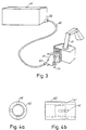
- Glass fibres are available in a store 41 and, in principle, these fibres can have been delivered in finely divided form.
- the store is part of the fibre tearing machine shown in Fig. 1 and glass fibres for the machine are delivered in the form of compressed fibre bales.
- the machine operates to tear the fibre bale into small fibre bundles which by means of air are blown into the conduit 20 to create in this conduit a fibre stream mixed with air.
- the means for generating said air stream have not been shown in the figure.
- air jets are introduced in the ejector 22 from different sides so that a vacuum is established sucking the fibres into said conduit and so that additional air is introduced into the conduit for the transport of fibres through same.
- FIGS 4a and 4b an embodiment of the ejector is shown in which four bores 42 open in an area of reduced cross-section, said bores being disposed crosswise.
- the bores extend in the direction of the fibre stream through the ejector but intersect this direction at an angle of about 30 degrees.
- the number of bores can be increased and in a modified embodiment, not shown, said number has been doubled and the bores have been evenly distributed along the periphery. A number of such modifications can be made within the scope of the idea of invention.
- an additional ejector is provided for the purpose of creating a suitably shaped fibre stream leaving the nozzle.
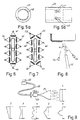
- the nozzle has an outlet opening which is mainly rectangular in order that the insulating layer applied be given the shape of a swath of a corresponding rectangular cross-section. Therefore, the object is to distribute the fibre flow evenly along the whole of the outlet opening and, accordingly, the ejector 23 is designed so as to apply a rotational movement of sufficient magnitude to the fibre stream in the conduit.
- FIGS 5a and 5b an embodiment is shown in which, as in the ejector 22, four bores 43 open inside the injector in an area of reduced diameter.
- the bores are directed tangentially to the circular inner wall of the ejector but also at an angle with respect to the direction of the fibre stream through the ejector, said angle, preferably, being at about 45 degrees.
- the number of bores can be varied as well as the disposition of same without departing from the idea of invention.
- a modified embodiment, not shown, has been tested in which eight bores have beeen evenly distributed along the periphery of the ejector.
- the ejectors 22 and 23 also contribute in additionally reducing the size of the fibre bundles leaving the fibre tearing machine.
- peripheral parts of the application nozzle have a greater cross-section than the central parts adjacent to the inlet opening of the nozzle.
- Fig. 8 two liquid nozzles 54, 55 are disposed at each side of the application nozzle 21.
- the nozzle 55 forms with the fibre stream an angle B which is smaller than the corresponding angle for the nozzle 54 resulting in that part of the liquid jet hitting the part of the oven cavity about to be hit by the fibre stream.
- the angle B is optimized so that wetting of the surface takes place without negatively influencing on the wetting of the fibre stream.
- another angle A has been drawn in indicating a certain inclination of the direction of the fibre stream from said nozzle with respect to the normal to the surface of the oven cavity. The purpose of this inclination is to minimize the fibre loss during application.
Landscapes
- Engineering & Computer Science (AREA)
- Chemical & Material Sciences (AREA)
- Textile Engineering (AREA)
- Mechanical Engineering (AREA)
- General Engineering & Computer Science (AREA)
- Composite Materials (AREA)
- Dispersion Chemistry (AREA)
- General Chemical & Material Sciences (AREA)
- Chemical Kinetics & Catalysis (AREA)
- Inorganic Chemistry (AREA)
- Combustion & Propulsion (AREA)
- Application Of Or Painting With Fluid Materials (AREA)
- Nonwoven Fabrics (AREA)
- Formation Of Insulating Films (AREA)
- Mechanical Treatment Of Semiconductor (AREA)
- Production Of Multi-Layered Print Wiring Board (AREA)
- Insulating Bodies (AREA)
Claims (14)
- Vorrichtung zum Aufbringen einer Isolierung auf eine Oberfläche eines Gegenstandes (10), umfassend einen Vorratsbehälter (15) für Fasern aus einem anorganischen Material, eine Leitungseinrichtung (20) zum Transport der Fasern von dem Vorratsbehälter (15) zu einer Sprühdüse (21), eine Einrichtung zum Erzeugen eines Luftstromes in der Leitungseinrichtung (20) in Richtung zu der Düse, eine erste Auswerfereinrichtung (22), die am Ende der Leitung gegenüber dem Vorratsbehälter (15) vorgesehen ist, um jeweils einen Luftstrahl in die Leitungseinrichtung (20) in Richtung des Faserstromes einzuleiten, eine zweite Auswerfereinrichtung (23), die am Ende der Leitungseinrichtung gegenüber der Sprühdüse (21) angeordnet ist, um jeweils einen Luftstrahl einzuleiten, der so gerichtet ist, dass er den Faserstrom in Drehung versetzt, und eine Einrichtung (24; 44-47; 48-53), die im Bereich der Sprühdüse (21) angeordnet ist, um jeweils einen Flüssigkeitsstrahl bestehend aus einer Mischung aus Wasser und einem Bindemittel in den Faserstrom ausserhalb der Sprühdüse einzuleiten, wobei der Flüssigkeitsstrahl jeweils in Richtung des Faserstromes eingeleitet wird, jedoch einen Winkel mit dem Strom bildet.
- Vorrichtung nach Anspruch 1, dadurch gekennzeichnet, dass die erste Auswerfereinrichtung (22) eine Anzahl von Düsen (42) umfasst, die am Umfang der Leitungseinrichtung verteilt sind, wobei die Düsen so gerichtet sind, dass der Luftstrahl von den Düsen mit dem vorbeiziehenden Faserstrom jeweils einen Winkel von etwa 30° bildet.
- Vorrichtung nach Anspruch 2, dadurch gekennzeichnet, dass acht Düsen (22) vorgesehen sind, die gleichmässig verteilt sind.
- Vorrichtung nach Anspruch 1, dadurch gekennzeichnet, dass die zweite Auswerfereinreichtung (23) mindestens vier Düsen (43) umfasst, die kreuzweise angeordnet sind und so gerichtet sind, dass der Luftstrahl von den Düsen jeweils tangential auf die Leitungseinrichtung (20) auftrifft, so dass ein Winkel von etwa 45° mit dem vorbeiziehenden Faserstrom gebildet wird.
- Vorrichtung nach Anspruch 1, dadurch gekennzeichnet, dass die Sprühdüse (21) ein zylindrisches Einlassteil bezitzt sowie ein Auslassteil, das hauptsächlich rechteckig ist, wobei die kürzere Seite hauptsächlich genauso gross ist wie der Durchmesser des Einlassteiles der Düse, während die längere Seite eine Grösse besitzt, die wesentlich grösser ist.
- Vorrichtung nach Anspruch 4, dadurch gekennzeichnet, dass eine Anzahl von Flüssigkeitsdüsen (24; 44, 45; 48, 49) in einer Reihe längs der längeren Seiten der Sprühdüse (21) auf beiden Seiten der Düse angeordnet sind.
- Vorrichtung nach Anspruch 6, dadurch gekennzeichnet, dass auf mindestens einer der kürzeren Seiten der Sprühdüse (21) mindestens eine Flüssigkeitsdüse (46, 47; 50-53) vorgesehen ist.
- Vorrichtung nach Anspruch 6, dadurch gekennzeichnet, dass mindestens eine Flüssigkeitsdüse (46, 47; 50-53) auf jeder der kürzeren Seiten vorgesehen ist.
- Vorrichtung nach einem der Ansprüche 5 bis 8, dadurch gekennzeichnet, dass Einrichtungen (11) vorgesehen sind, um die Oberfläche des Gegenstandes (10) an der Sprühdüse (21) vorbeizubewegen, die so gerichtet ist, dass der Faserstrom von der Düse auf die Oberfläche (10) in einem Winkel zur Bewegungsrichtung des Gegenstandes auftrifft, der etwas grösser ist als 90°.
- Vorrichtung nach Anspruch 7, dadurch gekennzeichnet, dass die Flüssigkeitsdüsen (55) in der in Bewegungsrichtung des Gegenstandes (10) vorderen Reihe so gerichtet sind, dass der Flüssigkeitsstrahl von den Düsen jeweils auch die Oberfläche des Gegenstandes benetzt, bevor die Fasern aufgebracht werden.
- Vorrichtung nach Anspruch 1, dadurch gekennzeichnet, dass das Bindemittel ein Bindemittel auf Silicatbasis ist.
- Vorrichtung nach Anspruch 4, dadurch gekennzeichnet, dass die Leitungseinrichtung (20) mit der Sprühdüse (21) verbunden ist, dass die Auslassrichtung des Faserstromes innerhalb eines Bereiches eingestellt werden kann, der durch die kürzeren Seiten der Auslassöffnung der Düse begrenzt wird.
- Vorrichtung nach einem der Ansprüche 1 bis 12, dadurch gekennzeichnet, dass sie eine Einrichtung zum Ausbilden der auf den Gegenstand (10) aufgebrachten benetzten Faserschicht und eine Einrichtung zum anschliessenden Trocknen der Schicht umfasst.
- Vorrichtung nach einem der Ansprüche 1 bis 13, dadurch gekennzeichnet, dass sie verwendet wird bei der Herstellung eines Ofens, der ringsum mit einer Wärmeisolierung versehen ist, die aus Fasern aus einem anorganischen Material, vorzugsweise aus Glasfasern oder Mineralfasern besteht.
Applications Claiming Priority (3)
| Application Number | Priority Date | Filing Date | Title |
|---|---|---|---|
| SE9102067 | 1991-07-02 | ||
| SE9102067A SE468722B (sv) | 1991-07-02 | 1991-07-02 | Anordning foer anbringande av en isolering innefattande fibrer paa en yta, innefattande ett organ foer alstrande av en luftstroem som bringar fiberstroemmen i rotation |
| PCT/SE1992/000466 WO1993001444A1 (en) | 1991-07-02 | 1992-06-24 | A method and a device for applying of an insulating layer on a surface of an object |
Publications (3)
| Publication Number | Publication Date |
|---|---|
| EP0550721A1 EP0550721A1 (de) | 1993-07-14 |
| EP0550721B1 EP0550721B1 (de) | 1994-12-28 |
| EP0550721B2 true EP0550721B2 (de) | 1997-07-23 |
Family
ID=20383237
Family Applications (1)
| Application Number | Title | Priority Date | Filing Date |
|---|---|---|---|
| EP92915255A Expired - Lifetime EP0550721B2 (de) | 1991-07-02 | 1992-06-24 | Vorrichtung zum anbringen einer isolierschicht an der oberfläche eines gegenstandes |
Country Status (8)
| Country | Link |
|---|---|
| US (1) | US5507869A (de) |
| EP (1) | EP0550721B2 (de) |
| AT (1) | ATE116417T1 (de) |
| CA (1) | CA2090871A1 (de) |
| DE (1) | DE69201051T3 (de) |
| DK (1) | DK0550721T3 (de) |
| SE (1) | SE468722B (de) |
| WO (1) | WO1993001444A1 (de) |
Families Citing this family (14)
| Publication number | Priority date | Publication date | Assignee | Title |
|---|---|---|---|---|
| DE29521023U1 (de) * | 1995-05-08 | 1996-08-01 | Krauss-Maffei AG, 80997 München | Reaktionsgießmaschine |
| DE19633947A1 (de) * | 1996-08-22 | 1998-02-26 | Bayerische Motoren Werke Ag | Anbauteil, insbesondere für Innenräume von Kraftfahrzeugen |
| US5947646A (en) * | 1997-02-25 | 1999-09-07 | Guardian Fiberglass, Inc. | System for blowing loose-fill insulation |
| US6261679B1 (en) | 1998-05-22 | 2001-07-17 | Kimberly-Clark Worldwide, Inc. | Fibrous absorbent material and methods of making the same |
| DE19848874A1 (de) * | 1998-10-22 | 2000-04-27 | Bsh Bosch Siemens Hausgeraete | Backofen |
| FR2801243B1 (fr) | 1999-11-18 | 2006-06-02 | Saint Gobain Isover | Procede pour appliquer une couche isolante sur une surface d'un objet et produit isole correspondant |
| DE10211331B4 (de) * | 2002-03-14 | 2006-02-02 | Sto Ag | Verfahren zum Herstellen einer aerogelhaltigen Dämmschicht auf einer Außenwand eines Gebäudes |
| AU2005223454A1 (en) * | 2004-03-18 | 2005-09-29 | Johns Manville | System and method for forming an insulation particle/air suspension |
| ITTO20120812A1 (it) * | 2012-09-18 | 2014-03-19 | Indesit Co Spa | Metodo per coibentare una muffola di forno per la cottura di alimenti |
| FR3054636B1 (fr) | 2016-08-01 | 2019-01-25 | Saint-Gobain Isover | Procede d'isolation et appareil obtenu |
| CN110983632A (zh) * | 2019-12-31 | 2020-04-10 | 重庆再升科技股份有限公司 | 一种集棉罩 |
| CN111074425A (zh) * | 2019-12-31 | 2020-04-28 | 重庆再升科技股份有限公司 | 一种高排水隔音隔热玻璃纤维棉毡的制备方法及产品 |
| CN111058186A (zh) * | 2019-12-31 | 2020-04-24 | 重庆再升科技股份有限公司 | 一种高强度隔音隔热玻璃纤维棉毡的制备方法及产品 |
| US20250239586A1 (en) * | 2024-01-18 | 2025-07-24 | Durr Systems, Inc. | Apparatus And Method For Inductive Heating Of Coated Web Substrates During Process Operations |
Family Cites Families (21)
| Publication number | Priority date | Publication date | Assignee | Title |
|---|---|---|---|---|
| US1702043A (en) * | 1923-09-15 | 1929-02-12 | Turner Tanning Machinery Co | Method and apparatus for applying and treating varnish |
| US1718507A (en) * | 1923-12-17 | 1929-06-25 | Wenzel | Heat insulation of walls |
| US2578412A (en) * | 1950-01-10 | 1951-12-11 | Emery J Fisher | Spray gun for comminuted material and adhesive |
| US3871583A (en) * | 1969-12-29 | 1975-03-18 | Paul H Kellert | Cement spray gun with remote air injection |
| FR2314775A1 (fr) * | 1975-06-18 | 1977-01-14 | Inst Francais Du Petrole | Appareillage pour former une couche d'un produit pulverulent sur la surface d'un objet |
| DE2719439C2 (de) * | 1977-04-30 | 1984-01-19 | Messerschmitt-Bölkow-Blohm GmbH, 8000 München | Schwenkbare Schubdüse zur Vektorsteuerung |
| DE2815616C2 (de) * | 1978-04-11 | 1982-11-18 | Woellner-Werke, 6700 Ludwigshafen | Verfahren zur Spritzisolierung von metallischen und/oder nichtmetallischen Gegenständen mit Mineralfasern und einem Bindemittel |
| IT1122846B (it) * | 1978-09-25 | 1986-04-23 | Woellner Werke | Procedimento per isolare a spruzzo oggetti metallici e/o non metallici |
| CA1190035A (en) * | 1982-01-06 | 1985-07-09 | Daniel D. O'connell | Sprayable acoustical composition |
| US4504602A (en) * | 1982-01-06 | 1985-03-12 | United States Gypsum Company | Sprayable acoustical composition |
| FR2535246A1 (fr) * | 1982-10-29 | 1984-05-04 | Saint Gobain Isover | Panneaux isolants d'etancheite de toitures, procede et dispositifs pour leur fabrication |
| US4542040A (en) * | 1982-12-13 | 1985-09-17 | Nowak David M | Method and means for spraying aggregates for fireproof insulation onto a substratum |
| JPS59205480A (ja) * | 1983-05-09 | 1984-11-21 | Usui Internatl Ind Co Ltd | 断熱エンジン部品用セラミツク溶射被覆層の強化法 |
| US4673594A (en) * | 1984-10-12 | 1987-06-16 | Manville Service Corporation | Method for applying a layer of fiber on a surface and a refractory material produced thereby |
| JPS61111973A (ja) * | 1984-10-31 | 1986-05-30 | 黒崎窯業株式会社 | 耐火吹付け材の吹付け方法 |
| EP0222563A1 (de) * | 1985-11-02 | 1987-05-20 | MB GROUP plc | Beschichtung von Gegenständen |
| US4814201A (en) * | 1987-08-31 | 1989-03-21 | Smith William H | Apparatus and method for applying a layer of fiber on a surface |
| US4968556A (en) * | 1988-03-25 | 1990-11-06 | The Reynolds Company | Coating for fiberglass insulation |
| US4852392A (en) * | 1988-08-12 | 1989-08-01 | Evans Robert G | High pressure drum testing apparatus and method |
| FR2640546B1 (fr) * | 1988-12-21 | 1991-04-12 | Saint Gobain Isover | Procede d'obtention d'un panneau d'isolation surface a base de fibres minerales |
| US5064689A (en) * | 1989-03-20 | 1991-11-12 | Weyerhaeuser Company | Method of treating discontinuous fibers |
-
1991
- 1991-07-02 SE SE9102067A patent/SE468722B/sv not_active IP Right Cessation
-
1992
- 1992-06-24 AT AT92915255T patent/ATE116417T1/de not_active IP Right Cessation
- 1992-06-24 DE DE69201051T patent/DE69201051T3/de not_active Expired - Fee Related
- 1992-06-24 CA CA002090871A patent/CA2090871A1/en not_active Abandoned
- 1992-06-24 EP EP92915255A patent/EP0550721B2/de not_active Expired - Lifetime
- 1992-06-24 DK DK92915255.1T patent/DK0550721T3/da active
- 1992-06-24 WO PCT/SE1992/000466 patent/WO1993001444A1/en not_active Ceased
- 1992-06-24 US US07/980,801 patent/US5507869A/en not_active Expired - Fee Related
Also Published As
| Publication number | Publication date |
|---|---|
| DE69201051D1 (de) | 1995-02-09 |
| SE9102067D0 (sv) | 1991-07-02 |
| DK0550721T3 (da) | 1995-05-29 |
| EP0550721B1 (de) | 1994-12-28 |
| EP0550721A1 (de) | 1993-07-14 |
| US5507869A (en) | 1996-04-16 |
| SE9102067L (sv) | 1993-01-03 |
| DE69201051T3 (de) | 1998-03-05 |
| SE468722B (sv) | 1993-03-08 |
| WO1993001444A1 (en) | 1993-01-21 |
| DE69201051T2 (de) | 1995-05-18 |
| CA2090871A1 (en) | 1993-01-03 |
| ATE116417T1 (de) | 1995-01-15 |
Similar Documents
| Publication | Publication Date | Title |
|---|---|---|
| EP0550721B1 (de) | Vorrichtung zum anbringen einer isolierschicht an der oberfläche eines gegenstandes | |
| US3311085A (en) | Apparatus for coating objects | |
| JPS5876562A (ja) | ガス流によつて運ばれる繊維の受入れ素子における分配を改良するための方法および装置 | |
| CA1106580A (en) | Spray method of refractory material | |
| WO2008085461A1 (en) | Improved cooling ring for use in manufacture of fiberglass wool | |
| AU732714B2 (en) | Method for coating fibers with glue | |
| EP0329118A2 (de) | Verfahren und Vorrichtung zum Herstellen einer Faserkolonne von bestimmter Form | |
| EP1204610A1 (de) | System zur vorbereitung von polymerverkapselten glassfaserteilchen | |
| CN113953131B (zh) | 一种飞机零部件喷涂方法 | |
| CZ160393A3 (en) | Process of forming a preformed product, and apparatus for making the same | |
| EP1042243A1 (de) | Verfahren und vorrichtung zum integrieren von organischen fasern mit mineralfasern | |
| US3343933A (en) | Binder distribution method for producing mineral wool board | |
| EP0142715B1 (de) | Isoliersystem | |
| MXPA02001062A (es) | Metodo y aparato para sellar capsulas y capsulas adecuadas para utilizarse en tal metodo y aparato. | |
| CA1135177A (en) | Device for cutting and shooting fibres with stabilised orientation | |
| US20210323010A1 (en) | Facility for producing glass wool and system for spraying products onto fibers of such a facility | |
| CN218796844U (zh) | 一种电池钢壳内壁石墨喷涂装置 | |
| US4923731A (en) | Novel preform screens and preform product | |
| JPH0231170Y2 (de) | ||
| JP7823716B2 (ja) | 吹付けノズル及び吹付施工システム | |
| KR102753275B1 (ko) | 내측 코팅이 용이한 용기 내부 코팅 시스템 | |
| EP0611844B1 (de) | Vorrichtung zum Konditionieren eines Materials mittels Dampf in einem Silo | |
| CN212820738U (zh) | 一种阀门球体用喷涂装置 | |
| JPH04232702A (ja) | 新規な繊維が載置された繊維含有材料 | |
| CN209348135U (zh) | 一种喷雾干燥机的防护结构 |
Legal Events
| Date | Code | Title | Description |
|---|---|---|---|
| PUAI | Public reference made under article 153(3) epc to a published international application that has entered the european phase |
Free format text: ORIGINAL CODE: 0009012 |
|
| 17P | Request for examination filed |
Effective date: 19930311 |
|
| AK | Designated contracting states |
Kind code of ref document: A1 Designated state(s): AT CH DE DK FR GB IT LI NL |
|
| 17Q | First examination report despatched |
Effective date: 19931008 |
|
| GRAA | (expected) grant |
Free format text: ORIGINAL CODE: 0009210 |
|
| REF | Corresponds to: |
Ref document number: 116417 Country of ref document: AT Date of ref document: 19950115 Kind code of ref document: T |
|
| REF | Corresponds to: |
Ref document number: 69201051 Country of ref document: DE Date of ref document: 19950209 |
|
| ITF | It: translation for a ep patent filed | ||
| ET | Fr: translation filed | ||
| REG | Reference to a national code |
Ref country code: DK Ref legal event code: T3 |
|
| PLBI | Opposition filed |
Free format text: ORIGINAL CODE: 0009260 |
|
| 26 | Opposition filed |
Opponent name: ROCKWOOL INTERNATIONAL A/S Effective date: 19950927 |
|
| NLR1 | Nl: opposition has been filed with the epo |
Opponent name: ROCKWOOL INTERNATIONAL A/S |
|
| PLBF | Reply of patent proprietor to notice(s) of opposition |
Free format text: ORIGINAL CODE: EPIDOS OBSO |
|
| PLAW | Interlocutory decision in opposition |
Free format text: ORIGINAL CODE: EPIDOS IDOP |
|
| PLAW | Interlocutory decision in opposition |
Free format text: ORIGINAL CODE: EPIDOS IDOP |
|
| PUAH | Patent maintained in amended form |
Free format text: ORIGINAL CODE: 0009272 |
|
| STAA | Information on the status of an ep patent application or granted ep patent |
Free format text: STATUS: PATENT MAINTAINED AS AMENDED |
|
| 27A | Patent maintained in amended form |
Effective date: 19970723 |
|
| AK | Designated contracting states |
Kind code of ref document: B2 Designated state(s): AT CH DE DK FR GB IT LI NL |
|
| REG | Reference to a national code |
Ref country code: CH Ref legal event code: AEN Free format text: AUFRECHTERHALTUNG DES PATENTES IN GEAENDERTER FORM |
|
| NLR2 | Nl: decision of opposition | ||
| ITF | It: translation for a ep patent filed | ||
| ET3 | Fr: translation filed ** decision concerning opposition | ||
| NLR3 | Nl: receipt of modified translations in the netherlands language after an opposition procedure | ||
| REG | Reference to a national code |
Ref country code: DK Ref legal event code: T4 |
|
| PGFP | Annual fee paid to national office [announced via postgrant information from national office to epo] |
Ref country code: FR Payment date: 19980609 Year of fee payment: 7 |
|
| PGFP | Annual fee paid to national office [announced via postgrant information from national office to epo] |
Ref country code: DK Payment date: 19980612 Year of fee payment: 7 |
|
| PGFP | Annual fee paid to national office [announced via postgrant information from national office to epo] |
Ref country code: AT Payment date: 19980615 Year of fee payment: 7 Ref country code: GB Payment date: 19980615 Year of fee payment: 7 |
|
| PGFP | Annual fee paid to national office [announced via postgrant information from national office to epo] |
Ref country code: NL Payment date: 19980629 Year of fee payment: 7 |
|
| PGFP | Annual fee paid to national office [announced via postgrant information from national office to epo] |
Ref country code: DE Payment date: 19980706 Year of fee payment: 7 |
|
| PGFP | Annual fee paid to national office [announced via postgrant information from national office to epo] |
Ref country code: CH Payment date: 19980708 Year of fee payment: 7 |
|
| PG25 | Lapsed in a contracting state [announced via postgrant information from national office to epo] |
Ref country code: GB Free format text: LAPSE BECAUSE OF NON-PAYMENT OF DUE FEES Effective date: 19990624 Ref country code: AT Free format text: LAPSE BECAUSE OF NON-PAYMENT OF DUE FEES Effective date: 19990624 |
|
| PG25 | Lapsed in a contracting state [announced via postgrant information from national office to epo] |
Ref country code: LI Free format text: LAPSE BECAUSE OF NON-PAYMENT OF DUE FEES Effective date: 19990630 Ref country code: FR Free format text: THE PATENT HAS BEEN ANNULLED BY A DECISION OF A NATIONAL AUTHORITY Effective date: 19990630 Ref country code: DK Free format text: LAPSE BECAUSE OF NON-PAYMENT OF DUE FEES Effective date: 19990630 Ref country code: CH Free format text: LAPSE BECAUSE OF NON-PAYMENT OF DUE FEES Effective date: 19990630 |
|
| PG25 | Lapsed in a contracting state [announced via postgrant information from national office to epo] |
Ref country code: NL Free format text: LAPSE BECAUSE OF NON-PAYMENT OF DUE FEES Effective date: 20000101 |
|
| REG | Reference to a national code |
Ref country code: CH Ref legal event code: PL |
|
| GBPC | Gb: european patent ceased through non-payment of renewal fee |
Effective date: 19990624 |
|
| NLV4 | Nl: lapsed or anulled due to non-payment of the annual fee |
Effective date: 20000101 |
|
| REG | Reference to a national code |
Ref country code: DK Ref legal event code: EBP |
|
| PG25 | Lapsed in a contracting state [announced via postgrant information from national office to epo] |
Ref country code: DE Free format text: LAPSE BECAUSE OF NON-PAYMENT OF DUE FEES Effective date: 20000503 |
|
| REG | Reference to a national code |
Ref country code: FR Ref legal event code: ST |
|
| PG25 | Lapsed in a contracting state [announced via postgrant information from national office to epo] |
Ref country code: IT Free format text: LAPSE BECAUSE OF NON-PAYMENT OF DUE FEES;WARNING: LAPSES OF ITALIAN PATENTS WITH EFFECTIVE DATE BEFORE 2007 MAY HAVE OCCURRED AT ANY TIME BEFORE 2007. THE CORRECT EFFECTIVE DATE MAY BE DIFFERENT FROM THE ONE RECORDED. Effective date: 20050624 |