EP0550764B1 - Verfahren zum bedienen einer vorrichtung zum fallenlassen von gegenständen - Google Patents
Verfahren zum bedienen einer vorrichtung zum fallenlassen von gegenständen Download PDFInfo
- Publication number
- EP0550764B1 EP0550764B1 EP92916139A EP92916139A EP0550764B1 EP 0550764 B1 EP0550764 B1 EP 0550764B1 EP 92916139 A EP92916139 A EP 92916139A EP 92916139 A EP92916139 A EP 92916139A EP 0550764 B1 EP0550764 B1 EP 0550764B1
- Authority
- EP
- European Patent Office
- Prior art keywords
- goods
- opening
- closing
- column
- drop out
- Prior art date
- Legal status (The legal status is an assumption and is not a legal conclusion. Google has not performed a legal analysis and makes no representation as to the accuracy of the status listed.)
- Expired - Lifetime
Links
Images



Classifications
-
- B—PERFORMING OPERATIONS; TRANSPORTING
- B65—CONVEYING; PACKING; STORING; HANDLING THIN OR FILAMENTARY MATERIAL
- B65G—TRANSPORT OR STORAGE DEVICES, e.g. CONVEYORS FOR LOADING OR TIPPING, SHOP CONVEYOR SYSTEMS OR PNEUMATIC TUBE CONVEYORS
- B65G1/00—Storing articles, individually or in orderly arrangement, in warehouses or magazines
- B65G1/02—Storage devices
- B65G1/04—Storage devices mechanical
- B65G1/06—Storage devices mechanical with means for presenting articles for removal at predetermined position or level
- B65G1/08—Storage devices mechanical with means for presenting articles for removal at predetermined position or level the articles being fed by gravity
-
- B—PERFORMING OPERATIONS; TRANSPORTING
- B65—CONVEYING; PACKING; STORING; HANDLING THIN OR FILAMENTARY MATERIAL
- B65G—TRANSPORT OR STORAGE DEVICES, e.g. CONVEYORS FOR LOADING OR TIPPING, SHOP CONVEYOR SYSTEMS OR PNEUMATIC TUBE CONVEYORS
- B65G1/00—Storing articles, individually or in orderly arrangement, in warehouses or magazines
- B65G1/02—Storage devices
- B65G1/04—Storage devices mechanical
- B65G1/137—Storage devices mechanical with arrangements or automatic control means for selecting which articles are to be removed
- B65G1/1373—Storage devices mechanical with arrangements or automatic control means for selecting which articles are to be removed for fulfilling orders in warehouses
- B65G1/1376—Storage devices mechanical with arrangements or automatic control means for selecting which articles are to be removed for fulfilling orders in warehouses the orders being assembled on a commissioning conveyor
-
- B—PERFORMING OPERATIONS; TRANSPORTING
- B65—CONVEYING; PACKING; STORING; HANDLING THIN OR FILAMENTARY MATERIAL
- B65G—TRANSPORT OR STORAGE DEVICES, e.g. CONVEYORS FOR LOADING OR TIPPING, SHOP CONVEYOR SYSTEMS OR PNEUMATIC TUBE CONVEYORS
- B65G2209/00—Indexing codes relating to order picking devices in General
- B65G2209/04—Indication location means
Definitions
- the present invention relates to a goods drop out device and method therefor. More particularly, the invention relates to a goods drop out device suitable for picking of goods in a goods delivery center and so forth.
- a number of the smaller opening and closing members corresponding to the number derived as a remainder after subtracting the maintained number of goods in the leading column and subtracting the number of goods per column are held open, and the larger opening and closing members of the leading column and n columns are moved simultaneously to enable the necessary number of goods to be dropped out.
- the arrangement patterns of the goods receptacle portions defined in the drop out boxes are differentiated so that the sizes of the bottom openings of respective goods receptacle portions to be opened and closed by the smaller opening and closing members are differentiated. Then, it can be considered to improve the efficiency of the facility by adapting the length of the smaller opening and closing member in the motion direction of the larger opening and closing member to an arrangement pattern having an average length in that direction and by using the smaller opening and closing members of this length in common to the arrangement pattern of the other goods receptacle portions of different length in that direction.
- the smaller opening and closing member of an average length is to be used in common to various arrangement patterns of the goods receptacle portions, and the smaller opening and closing members and the larger opening and closing members are operated in the manner set forth above, is not efficient for the arrangement pattern having a large number of columns due to small size of the goods. Namely, in the arrangement pattern having a large number of columns for small size goods, the tip end portions of the smaller opening and closing members can extend beyond the corresponding goods receptacle portions to partly block the bottoms of the goods receptacle portions in the adjacent column.
- An embodiment of the invention enables the certain drop out of a necessary total number when the common configuration of the smaller opening and closing members are designed to be used in common for various arrangement patterns of the goods receptacle portions.
- a method of operating a goods drop out device comprising a drop out box, a plurality of goods receptacle portions disposed in a matrix fashion within the drop out box, a first device which can open or close the bottoms of respective goods receptacle portions simultaneously in one column of the matrix, the first device being movable column by column, plural second devices provided on an end of said first device, the second devices being smaller than the first device, and capable of opening or closing the bottoms of respective goods receptacle portions independently whereby goods may be dropped from individual receptacle portions, the method comprising the steps of: when the number of goods maintained in a leading column holding goods in the drop out device is smaller than a required total number to be dropped out, initially opening all of said smaller opening and closing devices to drop out the goods from said leading column; when the required necessary number to be dropped out after dropping out of said leading column is in excess of the number of goods in a column, moving said first opening and closing device over a determined number of columns
- a method of operating a goods drop out device comprising a drop out box, a plurality of goods receptacle portions disposed in a matrix fashion within the drop out box, a first opening device which can open or close the bottoms of respective goods receptacle portions simultaneously in one column of the matrix, the first device being movable column by column, plural second devices provided on an end of said first device, the second devices being smaller than the first device, and capable of opening or closing the bottoms of respective goods receptacle portions independently whereby goods may be dropped from individual receptacle portions, the method comprising the steps of: when the number of goods maintained in a leading column holding goods in the drop out device is smaller than a required total number to be dropped out, initially opening all of said first smaller opening and closing devices to drop out the goods from said leading column; closing all of said smaller opening and closing devices after dropping out of goods; when the required necessary number to be dropped out after dropping out of said leading column is in excess of the number of goods in
- a goods drop out device having goods receptacle portions defined in a drop out box and opening and closing devices for opening and closing the bottoms of the goods receptacle portions, which comprises: the opening and closing devices each comprising an opening and closing member pivotable about a support shaft extending substantially in parallel to the bottom of the goods receptacle portion for opening and closing the bottom; a pushing rod contacting with the lower surface of the opening and closing member and moving toward and away from the lower surface; and an opening and closing cylinder device for driving the pushing rod and operating to close the bottom of the goods receptacle portion by pushing up the opening and closing member by the pushing rod.
- a goods dropping out method in which goods are stored in a plurality of goods receptacle portions defined by partitioning walls inserted into a drop out box, opening and closing devices provided on the bottoms of respective goods receptacle portions is operated to open to enable dropping out of the goods in respective goods receptacle portions, comprises the steps of: selecting insertion positions of the partitioning walls in the drop out box to modify an arrangement pattern of the goods receptacle portions in the drop out box; to provide a plurality of smaller opening and closing members corresponding to a minimum interval of the partitioning walls to be inserted into the drop out box in parallel relationship to each other; and operating all of smaller opening and closing members at least partly corresponding to the bottom of the goods receptacle portions upon dropping out the goods therefrom.
- a goods drop out device defining a plurality of goods receptacle portions defined by partitioning walls which are inserted into a drop out box, having an opening and closing device at the bottom of each of the goods receptacle portions so that dropping out of the goods in the goods receptacle portions by opening operation of the opening and closing device, which comprises: the partitioning walls have selectable insertion positions in the drop out box for modifying the arrangement pattern of the goods receptacle portions defined in the drop out box; and the opening and closing device includes a plurality of smaller opening and closing members corresponding to the minimum interval of the partitioning walls inserted, in parallel relationship to each other; and upon dropping out of the goods from respective goods receptacle portions, opening all of the smaller opening and closing members at least partly corresponding to the bottom of the goods receptacle portions.
- the pushing rods driven by the opening and closing cylinder devices contact the lower surfaces of the opening and closing members to close the bottom of the goods receptacle portions by pushing up the opening and closing members by the pushing rods and to open the bottom of the goods receptacle portions by pivoting due to the weights of the opening and closing members themselves in response to retraction of the pushing rods.
- the goods can be dropped out from the goods receptacle portions which are opened at the bottoms.
- the opening and closing cylinder devices having a uniform stroke are employed, the opening and closing members of the different length can be opened and closed with certainly.
- the bottom opening and closing members for the goods receptacle portions having different bottom opening sizes can be opened and closed with certainly to improve efficiency of facility.
- the arrangement pattern of the goods receptacle portions defined in the drop out box is changed by changing the inserting positions of the partitioning walls in the drop out box , and the smaller opening and closing members to be operated to open upon dropping out of the goods are appropriately selected corresponding to variation of the arrangement patterns of the goods receptacle portions. Namely, by changing the insertion position of the partitioning walls and selection of the smaller opening and closing members to be opened, it becomes possible to drop out a variety of sizes of goods employing the drop out devices having the same basic construction for improving the efficiency of the facility.
- the smaller opening and closing members corresponding to those goods receptacle portions are always set to an open condition. Accordingly, even when the same configuration of the smaller opening and closing members (for example, the smaller opening and closing member of an average length) is employed in common to various arrangement patterns of the goods receptacle portions and when it is applied to the arrangement pattern having a large number of columns due to small size of the goods, the tip ends of the smaller opening and closing members will never block the goods receptacle portions in the adjacent column even partly to enable to drop out with certainly a total necessary number of goods to be drop out.
- the same configuration of the smaller opening and closing members for example, the smaller opening and closing member of an average length
- the smaller opening and closing members are stopped in their open position for a predetermined period of time after dropping out.
- the period for stopping the smaller opening and closing members in their open position corresponds to a dropping out period of the goods.
- a picking device 10 is formed as a unit of a plurality of sets (for example, 20 sets) of reservoir devices 13 corresponding to each of a plurality of kinds of goods (for example 20 kinds), and a drop out devices 14 arranged with respect to a collecting conveyer 11 and a supplying conveyer 12 .
- the picking device 10 is arranged with three sets of reservoir devices 13 and the drop out devices 14 at three stages of proximal side, intermediate side and the distal side at a position opposing to a flow shelf 15 .
- Respective reservoir device 13 at the distal and intermediate side stages are adapted to move frontwardly, i.e. toward the flow shelf 15 above those in the intermediate and proximal side.
- a worker withdraws the reservoir device 13 which becomes empty from an original position toward the flow shelf 15 upon transferring the goods in goods box 16 to the flow shelf 15 , and pushes the reservoir device 13 , to which the goods are transferred, into the original position after transferring the goods into the reservoir device 13 at the position withdrawn toward the flow shelf 15 .
- the picking device 10 includes a transfer demand indicator 17 at the front face of each reservoir device 13 so that the fact that the reservoir becomes empty is indicated to the worker by flashing of the transfer demand indicator 17 .
- a transfer goods indicator 18 provided on the corresponding compartment of the flow shelf 15 also flashes.
- the picking device 10 is arranged with the drop out devices 14 beneath the reservoir devices 13 so that shutter devices 21 of the drop out devices 14 are operated to open to drop out a desired number of goods onto the collecting conveyer 11 after opening operation of shutter devices 19 of the reservoir devices 13 for transferring all goods transferred to the reservoir device 13 to the drop out device 14 at the downstream position.
- respective ones of the reservoir devices 13 and the drop out devices 14 are provided with partitioning walls 24 , 25 inserted into reservoir tanks 22 and drop out boxes 23 for defining a plurality of goods receptacle portions 26 , 27 .
- the goods stored in each goods box 16 stored in each compartment of the flow shelf 15 in random fashion or in a predetermined arrangement, are manually transferred by the worker into each goods receptacle portion 26 of the reservoir device 13 .
- the goods transferred into the reservoir device 13 are then transferred to each goods receptacle portion 27 of the drop out device 14 by opening control of the shutter device 19 as set forth above.
- the goods transferred to the drop device 14 are dropped out per the goods receptacle portion 27 by opening control of the shutter 21 as set forth above.
- the shutter devices 19 and the shutter devices 21 are controlled by a picking control device (not shown) provided in the picking device 10 .
- the picking device 10 is provided with an orienting device as discussed below in order to supply the goods dropped out from a plurality (for example, 20) of the drop out devices 14 forming one unit in the manner as set forth above into a container 32 on a container transporting line 31 in oriented fashion.
- the orienting device comprises a shoot 33 arranged at the lower side of the drop out devices 14 forming one unit along all of the drop out devices 14 of the picking device 10 , the above-mentioned collecting conveyer 11 being arranged along the drop out device 14 at the downstream of the shoot 33 and the above-mentioned supply conveyer 12 being arranged downstream of the collecting conveyer 11 for collecting the goods dropped out onto the collecting conveyer 11 .
- the goods for one container which are dropped out from respective drop out devices 14 are transferred to the collecting conveyer 11 via the shoot 33 and temporarily maintained on the collecting conveyer 11 .
- the collecting conveyer 11 After temporarily placing on the collecting conveyer 11 in the standby state, given the condition that the supply conveyer 12 becomes empty, the collecting conveyer 11 is driven to transfer the goods on the collecting conveyer 11 onto the supply conveyer 12 . Then, when the container 32 on the container transporting line 31 is discriminated that it is the container to put the above-mentioned goods based on a bar code put on the container 32 , the container 32 is stopped in front of the supply conveyer 12 . The supply conveyer 12 is then driven to supply the goods on the supply conveyer 12 into the container 32 .
- the detail of the reservoir device 13 and the drop out device 14 are as follows:
- the reservoir device 13 has a plurality of goods receptacle portions 26 defined in a matrix form of n columns and k rows by the partitioning walls 24 inserted into the reservoir tank 22 .
- the reservoir tank 22 has a large number of partitioning wall inserting slits similarly to the drop out box 23 illustrated in Fig. 5 .
- the arrangement pattern of the goods receptacle portions 26 defined in the reservoir tank 22 can be changed in the same manner as the drop out box 23 illustrated in Fig. 7 by changing the inserting positions of the partitioning walls 24 in the common reservoir tank 22 .
- the bottom of the goods receptacle portions 26 defined in the reservoir tank 22 is designed to be opened and closed by the above-mentioned shutter device 19 .
- the shutter device 19 comprises a pair of left and right large diameter gears 42 driven by a motor 41 and three sets of pairs of left and right smaller diameter idler gears 43 arranged at insides of left and right side plates of the reservoir tank 22 and a plurality of struts are sequentially supported on parts of a pair of endless circulating chains 44 engaged with these gears 42 and 43 to form an opening and closing member 45 .
- the shutter device 19 moves the opening and closing member 45 in column direction (see Fig.
- the drop out device 14 has a plurality of goods receptacle portions 27 in the matrix form of n columns and k rows corresponding to the goods receptacle portions 26 formed in the upper side reservoir device 13 , defined by the partitioning walls 25 inserted into the drop out box 23 .
- the drop out box 23 has a large number of partitioning wall receptacle slits 50 , as shown in Figs. 5 and 6 .
- the arrangement patterns of the goods receptacle portions 27 defined in the drop out box 23 can be changed as shown in Fig. 7 by changing the inserting positions of the partitioning walls 25 in the common drop out box 23 .
- a pattern capable of storing the goods and having maximum frequency of storing is selected among various patterns of Fig. 7 .
- the bottom of the goods receptacle portions 27 formed in the drop out box 23 can be opened and closed by the shutter device 21 set forth above.
- the shutter device 21 comprises a pair of left and right large diameter gears 52 driven by a motor 51 and three sets of pairs of left and right smaller diameter idler gears 53 arranged at insides of left and right side plates of the drop out box 23 .
- a larger opening and closing member 55 and a plurality of smaller opening and closing members 56 are provided on a pair of endless circulating chains 54 engaged with these gears 52 and 53 .
- the large opening and closing member 55 is formed by sequentially supporting a plurality of struts on parts of the chains 54 . Namely, the shutter device 21 moves the large opening and closing member 55 in the row direction (see Fig. 6 ) in response to driving of the motor 51 under control of the picking control device as set forth above to simultaneously open the bottoms of the goods receptacle portions 27 of one column.
- respective smaller opening and closing members 56 are supported by supporting members 57 provided on the chain 54 for arranging at the tip end of the larger opening and closing member 55 and so as to be supported in parallel relationship to each other and pivoted about a support shaft 58 extending substantially parallel to the bottoms of the goods receptacle portions 27 for opening and closing the bottoms.
- a pushing rod guide 61 supported by a support member 59 provided on the chain 54 , pushing rods 62 and opening and closing cylinder devices 63 corresponding to respective smaller opening and closing members 56 are supported.
- the pushing rod 62 contacts the lower surface of the smaller opening and closing member 56 and moves toward and away from the lower surface under the guidance of the pushing rod guide 61 .
- the opening and closing cylinder device 63 drives the pushing rod 62 to push up the smaller opening and closing member 56 by the pushing rod 62 for closing motion of the bottom of the goods receptacle portion 27 .
- the smaller opening and closing member 56 opens the bottom of the goods receptacle portion 27 by rotating due to its own weight when the opening and closing cylinder device 63 retracts the pushing rod 62 .
- the smaller opening and closing member 56 can open and close the bottom of the corresponding goods receptacle portion 27 independently.
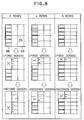
- the smaller opening and closing member 56 is sized corresponding to a minimum interval of the partitioning walls 25 inserted in the drop out box 23 , and a plurality of the smaller opening and closing members 56 of the relevant size are provided in parallel. For instance, assuming the minimum interval of the above-mentioned partitioning walls 25 is w6 (see Fig. 7 ) corresponding to 6 rows arrangement pattern of Fig. 8 , the small opening and closing members 56 of the size in the column direction coincident with w6 (see Fig. 6 ) are employed. Then, a total of 6 smaller opening and closing members 56 are arranged on the tip end of the larger opening and closing member 55 .
- step (2) After dropping out the goods in all of the goods receptacle portions 27 in 1 column through the above-mentioned step (2), the larger opening and closing member 55 is shifted for one column by actuation of the motor 51 while all smaller opening and closing members 56 are operated for closing. Subsequently, the above-mentioned process of (2) will be repeated as required.
- the pushing rods 62 driven by the opening and closing cylinder devices 63 contact the lower surfaces of the smaller opening and closing members 56 to close the bottom of the goods receptacle portions 27 by pushing up the smaller opening and closing members 56 by the pushing rods 62 and to open the bottom of the goods receptacle portions 27 by pivoting due to the weights of the smaller opening and closing members 56 themselves in response to retraction of the pushing rods 62 .
- the goods can be dropped out from the goods receptacle portions 27 which are opened at the bottom.
- the opening and closing cylinder devices 63 having a uniform stroke are employed, the smaller opening and closing members 56 of the different length can be opened and closed with certainly.
- the bottom opening and closing members for the goods receptacle portions 27 having different bottom opening sizes can be opened and closed with certainly to improve efficiency of facility.
- the arrangement pattern of the goods receptacle portions 27 defined in the drop out box 23 is changed by changing the inserting positions of the partitioning walls 25 in the drop out box 23 , and the smaller opening and closing members 56 to be operated to open upon dropping out of the goods are appropriately selected corresponding to variation of the arrangement patterns of the goods receptacle portions 27 .
- the insertion position of the partitioning walls 25 and selection of the smaller opening and closing members 56 to be opened and closed it becomes possible to drop out a variety of sizes of goods employing drop out devices 14 having the same basic construction for improving the efficiency of the facility.
- the smaller opening and closing members 56 having sufficient length L (average length or maximum length of l segments of all arrangement pattern or so forth) for preventing the goods from falling off the goods receptacle portion 27 defined in the cut out box 23 are arranged in parallel relationship.
- L average length or maximum length of l segments of all arrangement pattern or so forth
- the smaller opening and closing member 56 having the size in the column direction (see Fig. 6 ) coincident with w6, and the size in the row direction (see Fig. 6 ) being above-mentioned L is employed so that a total of 6 smaller opening and closing members 56 are arranged at the tip end of the larger opening and closing member 55 .
- the length L of the smaller opening and closing member 56 is smaller than the length l of the goods receptacle portion 27 . Therefore, when the necessary number to be dropped out is 7, it is possible to open only one smaller opening and closing member 56 and move the large opening and closing member 55 over one column for dropping out all 7 goods in one action, as an alternative of the above-mentioned method of the invention.
- the opening and closing process of the smaller opening and closing members 56 and the larger opening and closing member 55 for dropping out the goods are as follows:
- the opening and closing process of the smaller opening and closing members 56 and the larger opening and closing member 55 for dropping out the goods are as follows:
- the smaller opening and closing members 56 corresponding to those goods receptacle portions 27 are always set to the open condition. Accordingly, even when the same configuration of the smaller opening and closing members 56 (for example, smaller opening and closing members of an average length) is employed in common to various arrangement patterns of the goods receptacle portions 27 and when it is applied to the arrangement pattern having a large number of columns due to small size of the goods, the tip ends of the smaller opening and closing members 56 will never block the goods receptacle portions 27 in the adjacent column even partly to enable the total necessary number of goods to be dropped out with certainly.
- the same configuration of the smaller opening and closing members 56 for example, smaller opening and closing members of an average length
- the smaller opening and closing members which have been opened for opening the bottom of the goods receptacle portions for dropping out the goods may be stored at an open position for the predetermined period after dropping out in advance of a closing operation of the smaller opening and closing members.
- a facility efficiency can be improved by employing the opening and closing cylinder devices having uniform stroke length and assuring opening and closing of the bottom opening and closing members for the goods receptacle portions having different bottom opening sizes.
- the drop out device having a common basic construction, it is enabled to drop out a variety of sizes of goods to improve the efficiency of facility.
Landscapes
- Engineering & Computer Science (AREA)
- Mechanical Engineering (AREA)
- De-Stacking Of Articles (AREA)
- Warehouses Or Storage Devices (AREA)
- Vending Machines For Individual Products (AREA)
- Details Of Cutting Devices (AREA)
- Control And Other Processes For Unpacking Of Materials (AREA)
Claims (5)
- Verfahren zum Betreiben einer Warenauswerfvorrichtung mit einem Auswerfkasten (14), einer Anzahl von Warenaufnahmeabteilen (27), die in einer Matrixform innerhalb des Auswerfkastens angeordnet sind, einer ersten Einrichtung (55), welche die Böden der jeweiligen Warenaufnahmeabteile gleichzeitig in einer Spalte der Matrix öffnen oder verschließen kann, wobei die erste Einrichtung (55) spaltenweise verschiebbar ist, mehreren zweiten Einrichtungen (56), die an einem Ende der ersten Einrichtung (55) vorgesehen sind, wobei die zweiten Einrichtungen (56) kleiner sind als die erste Einrichtung (55) und die Böden jeweiliger Warenaufnahmeabteile (27) unabhängig öffnen oder schließen können, wodurch Waren aus einzelnen Aufnahmeabteilen ausgeworfen werden können, wobei das Verfahren die folgenden Schritte umfaßt: wenn die Anzahl von Waren, die in einer vorderen Spalte, die Waren in der Auswerfvorrichtung aufnimmt, enthalten sind, kleiner ist als eine erforderliche auszuwerfende Gesamtzahl, anfängliches Öffnen aller der kleineren Öffnungs- und Verschließeinrichtungen, um die Waren aus der vorderen Spalte auszuwerfen; wenn die erforderliche auszuwerfende Anzahl nach dem Auswerfen aus der vorderen Spalte größer ist als die Anzahl von Waren in einer Spalte, Verschieben der ersten Öffnungs- und Verschließeinrichtung über eine vorbestimmte Anzahl von Spalten, wobei alle kleinere Öffnungs- und Verschließeinrichtungen im offenen Zustand zum spaltenweisen Auswerfen der Waren gehalten werden; und Verschieben der ersten Öffnungs- und Verschließeinrichtung (55) über eine Spalte, wobei nur die Anzahl der kleineren Öffnungs- und Verschließeinrichtungen (56) geöffnet wird, welche der verbleibenden erforderlichen auszuwerfenden Anzahl entspricht, und die verbleibenden kleineren Öffnungs- und Verschließeinrichtungen (56) geschlossen sind.
- Verfahren zum Betreiben einer Warenauswerfvorrichtung mit einem Auswerfkasten (14), einer Anzahl von Warenaufnahmeabteilen (27), welche in einer Matrixform innerhalb des Auswerfkastens angeordnet sind, einer ersten Öffnungseinrichtung (55), welche die Böden von jeweiligen Warenaufnahmeabteilen gleichzeitig in einer Spalte der Matrix öffnen oder verschließen kann, wobei die erste Einrichtung (55) spaltenweise verschiebbar ist, mehreren zweiten Einrichtungen, die an einem Ende der ersten Einrichtung (55) vorgesehen sind, wobei die zweiten Einrichtungen (56) kleiner sind als die erste Einrichtung (55) und die Böden von jeweiligen Warenaufnahmeabteilen (27) unabhängig öffnen oder verschließen können, wodurch Waren aus einzelnen Aufnahmeabteilen ausgeworfen werden können, wobei das Verfahren die folgenden Schritte umfaßt: wenn die Anzahl von Waren, die in einer vorderen Spalte, welche Waren in der Auswerfvorrichtung aufnimmt, enthalten sind, kleiner ist als die erforderliche auszuwerfende Gesamtzahl, anfängliches Öffnen aller ersten kleineren Öffnungs- und Verschließeinrichtungen (56), um die Waren aus der vorderen Spalte auszuwerfen; Verschließen aller kleineren Öffnungs- und Verschließeinrichtungen (56) nach dem Auswerfen der Waren; wenn die erforderliche auszuwerfende Anzahl nach dem Auswerfen der vorderen Spalte größer ist als die Anzahl von Waren in einer Spalte, Verschieben der ersten Öffnungs- und Verschließeinrichtung (55) über lediglich eine Spalte, Wiederholen des Öffnens aller ersten Einrichtungen (56) zum Auswerfen von Waren aus einer Spalte; und nach dem Auswerfen Betätigen lediglich einer Anzahl von kleineren Öffnungs- und Verschließorganen entsprechend der verbleibenden erforderlichen Anzahl, die nach dem vorangehenden Auswerfvorgang auszuwerfen sind.
- Verfahren nach Anspruch 1 oder 2, bei welchem, wenn die Waren in einer Anzahl von Spalten auszuwerfen sind, die zweiten kleineren Öffnungs- und Verschließeinrichtungen (56), die zum Öffnen des Bodens der Warenaufnahmeabteile geöffnet worden sind, für eine voreingestellte Zeitspanne vor dem Verschließen offengehalten werden.
- Verfahren nach einem der Ansprüche 1 bis 3, bei welchem jede zweite Einrichtung ein Öffnungs- und Verschließorgan aufweist, das um einen Halteschaft verschwenkbar ist, der sich im wesentlichen parallel zum Boden des Warenaufnahmeabteils zum Öffnen und Verschließen dieses Bodens erstreckt; eine Schubstange, die mit der unteren Fläche des Öffnungs- und Verschließorgans in Berührung kommt und sich auf diese untere Fläche zu und von dieser weg bewegt; sowie eine Öffnungs- und Verschließzylindereinrichtung zum Antreiben der Schubstange und zum Verschließen des Bodens des Warenaufnahmeabteils durch Aufwärtsdrücken des Öffnungs- und Verschließorgans durch die Schubstange, und bei welchem der Verschließschritt eine Betätigung der Zylindereinrichtung umfaßt, um die Schubstange dadurch anzutreiben und das Öffnungs- und Verschließorgan nach oben zu drücken.
- Verfahren nach einem der vorangehenden Ansprüche, bei welchem die Warenaufnahmeabteile durch Trennwände gebildet sind, welche in den Auswerfkasten eingesetzt sind, wobei das Verfahren die folgenden Schritte umfaßt: Auswählen der Einsetzstellen von Trennwänden in den Auswerfkasten, um ein Anordnungsmuster der Warenaufnahmeabteile in dem Auswerfkasten zu verändern; und Öffnen aller zweiten kleineren Öffnungs- und Verschließorgane, die wenigstens teilweise dem Boden von ausgewählten Warenaufnahmeabteilen entsprechen, um die Waren daraus auszuwerfen.
Priority Applications (1)
| Application Number | Priority Date | Filing Date | Title |
|---|---|---|---|
| EP95115936A EP0705775B1 (de) | 1991-08-01 | 1992-07-29 | Vorrichtung und Verfahren zur Freigabe von Artikeln |
Applications Claiming Priority (7)
| Application Number | Priority Date | Filing Date | Title |
|---|---|---|---|
| JP214229/91 | 1991-08-01 | ||
| JP21422991A JPH0780573B2 (ja) | 1991-08-01 | 1991-08-01 | 物品の切り出し装置 |
| JP214230/91 | 1991-08-01 | ||
| JP21423091 | 1991-08-01 | ||
| JP21422891A JPH0780572B2 (ja) | 1991-08-01 | 1991-08-01 | 物品の切り出し方法及び装置 |
| JP214228/91 | 1991-08-01 | ||
| PCT/JP1992/000962 WO1993002951A1 (fr) | 1991-08-01 | 1992-07-29 | Procede et dispositif de decoupe d'articles |
Related Child Applications (2)
| Application Number | Title | Priority Date | Filing Date |
|---|---|---|---|
| EP95115936A Division EP0705775B1 (de) | 1991-08-01 | 1992-07-29 | Vorrichtung und Verfahren zur Freigabe von Artikeln |
| EP95115936.7 Division-Into | 1992-07-29 |
Publications (3)
| Publication Number | Publication Date |
|---|---|
| EP0550764A1 EP0550764A1 (de) | 1993-07-14 |
| EP0550764A4 EP0550764A4 (en) | 1993-12-08 |
| EP0550764B1 true EP0550764B1 (de) | 1996-09-25 |
Family
ID=27329592
Family Applications (2)
| Application Number | Title | Priority Date | Filing Date |
|---|---|---|---|
| EP92916139A Expired - Lifetime EP0550764B1 (de) | 1991-08-01 | 1992-07-29 | Verfahren zum bedienen einer vorrichtung zum fallenlassen von gegenständen |
| EP95115936A Expired - Lifetime EP0705775B1 (de) | 1991-08-01 | 1992-07-29 | Vorrichtung und Verfahren zur Freigabe von Artikeln |
Family Applications After (1)
| Application Number | Title | Priority Date | Filing Date |
|---|---|---|---|
| EP95115936A Expired - Lifetime EP0705775B1 (de) | 1991-08-01 | 1992-07-29 | Vorrichtung und Verfahren zur Freigabe von Artikeln |
Country Status (4)
| Country | Link |
|---|---|
| US (3) | US5482423A (de) |
| EP (2) | EP0550764B1 (de) |
| DE (2) | DE69214117T2 (de) |
| WO (1) | WO1993002951A1 (de) |
Families Citing this family (12)
| Publication number | Priority date | Publication date | Assignee | Title |
|---|---|---|---|---|
| AT402911B (de) * | 1995-07-18 | 1997-09-25 | Knapp Holding Gmbh | Kommissioniersystem |
| US7925376B2 (en) | 2002-01-14 | 2011-04-12 | Walgreen Co. | Dump station apparatus and method for filling stock orders |
| US7392913B2 (en) | 2002-12-13 | 2008-07-01 | Mcglynn Michael | Self-adjusting volume display and merchandise dispensing system |
| DE102006057266B4 (de) | 2006-11-23 | 2011-03-24 | SSI Schäfer Noell GmbH Lager- und Systemtechnik | Sortier- und Verteilsystem sowie Kommissionieranlage mit einem derartigen System |
| CN103538908A (zh) * | 2013-09-30 | 2014-01-29 | 昆山中士设备工业有限公司 | 适用于螺杆的货架 |
| GB2544648A (en) * | 2015-11-11 | 2017-05-24 | Ocado Innovation Ltd | Storage containers, bins and devices |
| EP3199954B1 (de) * | 2016-01-29 | 2022-05-04 | Beckman Coulter, Inc. | Lagersystem und verfahren zum lagern von material |
| US10521562B2 (en) | 2016-06-02 | 2019-12-31 | Becton Dickinson Rowa Germany Gmbh | Automatic picking machine for filling a transport container |
| DK3251980T3 (da) * | 2016-06-02 | 2021-01-25 | Becton Dickinson Rowa Germany Gmbh | Plukkerobot med en indretning til fyldning af hver af en række transportbeholdere med en gruppe lægemiddelpakninger svarende til en bestilling |
| CN110550367B (zh) * | 2019-09-10 | 2021-06-01 | 长江师范学院 | 用于存取汽车零部件的半自动存取配货架系统 |
| CH720747A1 (de) * | 2023-04-28 | 2024-11-15 | Ferag Ag | Kommissionierungsanlage und verfahren zum kommissionieren von stückgütern |
| FR3164989A1 (fr) * | 2024-07-29 | 2026-01-30 | Jalde | Installation de stockage et de distribution d’articles de marchandises, centre logistique et procédé de préparation de commandes |
Family Cites Families (16)
| Publication number | Priority date | Publication date | Assignee | Title |
|---|---|---|---|---|
| BE644686A (de) * | ||||
| US2718326A (en) * | 1950-12-29 | 1955-09-20 | Swank Inc | Tray with variable number of uniform size cells |
| US2704144A (en) * | 1951-07-11 | 1955-03-15 | Rety Stephen Paul | Delivery chute |
| US3028028A (en) * | 1959-08-21 | 1962-04-03 | Arenco Ab | Device on machines for filling collapsible tubes |
| DE2023102C3 (de) * | 1970-05-12 | 1974-03-14 | Licentia Patent-Verwaltungs-Gmbh, 6000 Frankfurt | Durchstimmbarer Oszillator für ein Gerät der Nachrichtentechnik |
| CH630020A5 (de) * | 1978-06-13 | 1982-05-28 | Wez Kunststoff | Vorrichtung zur halterung und lagerung von plattenfoermigen gegenstaenden. |
| JPS63176622A (ja) * | 1987-01-14 | 1988-07-20 | Maruyama Seisakusho:Kk | 二サイクルエンジンの吸入装置 |
| JP2548163B2 (ja) * | 1987-01-14 | 1996-10-30 | バブコツク日立株式会社 | スプレ−式脱硫塔 |
| JPH0650418Y2 (ja) * | 1987-05-06 | 1994-12-21 | ト−ヨ−カネツ株式会社 | 製品切出し装置 |
| US5020965A (en) * | 1988-04-28 | 1991-06-04 | Kao Corporation | Method for shifting goods and apparatus therefor |
| JPH0638008Y2 (ja) * | 1988-12-26 | 1994-10-05 | 花王株式会社 | 物品の取り出し装置 |
| JP2645103B2 (ja) * | 1988-09-22 | 1997-08-25 | 株式会社東芝 | 地熱蒸気タービンバイパス制御装置 |
| JP2627557B2 (ja) * | 1989-06-30 | 1997-07-09 | キヤノン株式会社 | 光学部品の保持手段 |
| JPH0333811U (de) * | 1989-08-10 | 1991-04-03 | ||
| DE69009983T2 (de) * | 1990-04-27 | 1994-11-03 | Kao Corp | Vorrichtung und Verfahren zum Handhaben von Waren. |
| US5020165A (en) * | 1990-09-28 | 1991-06-04 | Clark Huang | Toilet seat raising apparatus |
-
1992
- 1992-07-29 DE DE69214117T patent/DE69214117T2/de not_active Expired - Fee Related
- 1992-07-29 US US08/030,352 patent/US5482423A/en not_active Expired - Fee Related
- 1992-07-29 WO PCT/JP1992/000962 patent/WO1993002951A1/ja not_active Ceased
- 1992-07-29 EP EP92916139A patent/EP0550764B1/de not_active Expired - Lifetime
- 1992-07-29 EP EP95115936A patent/EP0705775B1/de not_active Expired - Lifetime
- 1992-07-29 DE DE69225617T patent/DE69225617T2/de not_active Expired - Fee Related
-
1995
- 1995-09-26 US US08/534,125 patent/US5628613A/en not_active Expired - Fee Related
-
1996
- 1996-12-26 US US08/773,072 patent/US5759009A/en not_active Expired - Fee Related
Also Published As
| Publication number | Publication date |
|---|---|
| EP0705775B1 (de) | 1998-05-20 |
| EP0550764A4 (en) | 1993-12-08 |
| WO1993002951A1 (fr) | 1993-02-18 |
| US5759009A (en) | 1998-06-02 |
| US5628613A (en) | 1997-05-13 |
| US5482423A (en) | 1996-01-09 |
| DE69214117D1 (de) | 1996-10-31 |
| DE69225617D1 (de) | 1998-06-25 |
| EP0705775A2 (de) | 1996-04-10 |
| EP0550764A1 (de) | 1993-07-14 |
| EP0705775A3 (de) | 1996-04-24 |
| DE69225617T2 (de) | 1998-11-26 |
| DE69214117T2 (de) | 1997-03-06 |
Similar Documents
| Publication | Publication Date | Title |
|---|---|---|
| EP0705775B1 (de) | Vorrichtung und Verfahren zur Freigabe von Artikeln | |
| US5672039A (en) | Order consolidation indexing system | |
| EP0416712B1 (de) | Verkaufsautomat | |
| US6061607A (en) | Order pick system | |
| EP0339610B1 (de) | Verfahren und Vorrichtung zum Kommissionieren von Artikeln bei Umdrehen einer Verpackung | |
| EP0581761B1 (de) | Automatische Ausgabevorrichtung für Eiscremetorten und dergl. | |
| JPS631607A (ja) | 品物入替装置とその駆動方法 | |
| EP0598397B1 (de) | Entladeeinheit einer Fördereinrichtung und Verfahren zum Entladen von der Fördereinrichtung | |
| EP0453682B1 (de) | Vorrichtung und Verfahren zum Handhaben von Waren | |
| JPS6368014A (ja) | 植物を移植するための方法及び装置 | |
| US3525443A (en) | Counting and stacking apparatus | |
| EP0445172B1 (de) | Anlage zur behandlung von backgut | |
| EP1196338B1 (de) | System zum lagern und auslagern | |
| US5615994A (en) | Article conveying, grouping and storing apparatus | |
| US20030091411A1 (en) | Automated storage extraction system | |
| DE19714455A1 (de) | Verfahren und Vorrichtung zum automatischen Kommissionieren von Artikeln | |
| JPH03500406A (ja) | 連続した処理作業箇所に沿って物品搬送具を搬送する装置 | |
| DE60001711T2 (de) | Automatisches Verteilsystem für Gegenstände zum Kommissionieren einer oder mehrerer Bestellunguen | |
| JPH0780572B2 (ja) | 物品の切り出し方法及び装置 | |
| JPH0815941B2 (ja) | 物品の切り出し方法 | |
| DE10064699C2 (de) | Kommissionieranlage mit Durchlaufregel und Befüllungseinrichtung | |
| DE2117726C3 (de) | Regal zur archivmäßigen Aufbewahrung und zur selbsttätigen Ausgabe von Tonbandkassetten und ähnlichen Behältnissen | |
| JPH0780573B2 (ja) | 物品の切り出し装置 | |
| KR0154238B1 (ko) | 리튬전지의 자동 적재장치 | |
| JPH06156712A (ja) | コンベヤ装置からの物品排出方法及び装置 |
Legal Events
| Date | Code | Title | Description |
|---|---|---|---|
| PUAI | Public reference made under article 153(3) epc to a published international application that has entered the european phase |
Free format text: ORIGINAL CODE: 0009012 |
|
| 17P | Request for examination filed |
Effective date: 19930330 |
|
| AK | Designated contracting states |
Kind code of ref document: A1 Designated state(s): CH DE FR GB LI NL SE |
|
| A4 | Supplementary search report drawn up and despatched |
Effective date: 19931021 |
|
| AK | Designated contracting states |
Kind code of ref document: A4 Designated state(s): CH DE FR GB LI NL SE |
|
| 17Q | First examination report despatched |
Effective date: 19950202 |
|
| GRAH | Despatch of communication of intention to grant a patent |
Free format text: ORIGINAL CODE: EPIDOS IGRA |
|
| GRAH | Despatch of communication of intention to grant a patent |
Free format text: ORIGINAL CODE: EPIDOS IGRA |
|
| GRAA | (expected) grant |
Free format text: ORIGINAL CODE: 0009210 |
|
| AK | Designated contracting states |
Kind code of ref document: B1 Designated state(s): CH DE FR GB LI NL SE |
|
| XX | Miscellaneous (additional remarks) |
Free format text: TEILANMELDUNG 95115936.7 EINGEREICHT AM 10/10/95. |
|
| REG | Reference to a national code |
Ref country code: CH Ref legal event code: NV Representative=s name: BOVARD AG PATENTANWAELTE |
|
| DX | Miscellaneous (deleted) | ||
| REF | Corresponds to: |
Ref document number: 69214117 Country of ref document: DE Date of ref document: 19961031 |
|
| ET | Fr: translation filed | ||
| PGFP | Annual fee paid to national office [announced via postgrant information from national office to epo] |
Ref country code: GB Payment date: 19970721 Year of fee payment: 6 |
|
| PGFP | Annual fee paid to national office [announced via postgrant information from national office to epo] |
Ref country code: DE Payment date: 19970801 Year of fee payment: 6 |
|
| PLBE | No opposition filed within time limit |
Free format text: ORIGINAL CODE: 0009261 |
|
| STAA | Information on the status of an ep patent application or granted ep patent |
Free format text: STATUS: NO OPPOSITION FILED WITHIN TIME LIMIT |
|
| PGFP | Annual fee paid to national office [announced via postgrant information from national office to epo] |
Ref country code: CH Payment date: 19970806 Year of fee payment: 6 |
|
| 26N | No opposition filed | ||
| PGFP | Annual fee paid to national office [announced via postgrant information from national office to epo] |
Ref country code: SE Payment date: 19980707 Year of fee payment: 7 |
|
| PGFP | Annual fee paid to national office [announced via postgrant information from national office to epo] |
Ref country code: FR Payment date: 19980709 Year of fee payment: 7 |
|
| PGFP | Annual fee paid to national office [announced via postgrant information from national office to epo] |
Ref country code: NL Payment date: 19980728 Year of fee payment: 7 |
|
| PG25 | Lapsed in a contracting state [announced via postgrant information from national office to epo] |
Ref country code: GB Free format text: LAPSE BECAUSE OF NON-PAYMENT OF DUE FEES Effective date: 19980729 |
|
| PG25 | Lapsed in a contracting state [announced via postgrant information from national office to epo] |
Ref country code: LI Free format text: LAPSE BECAUSE OF NON-PAYMENT OF DUE FEES Effective date: 19980731 Ref country code: CH Free format text: LAPSE BECAUSE OF NON-PAYMENT OF DUE FEES Effective date: 19980731 |
|
| REG | Reference to a national code |
Ref country code: CH Ref legal event code: PL |
|
| GBPC | Gb: european patent ceased through non-payment of renewal fee |
Effective date: 19980729 |
|
| PG25 | Lapsed in a contracting state [announced via postgrant information from national office to epo] |
Ref country code: DE Free format text: LAPSE BECAUSE OF NON-PAYMENT OF DUE FEES Effective date: 19990501 |
|
| PG25 | Lapsed in a contracting state [announced via postgrant information from national office to epo] |
Ref country code: SE Free format text: THE PATENT HAS BEEN ANNULLED BY A DECISION OF A NATIONAL AUTHORITY Effective date: 19990730 |
|
| PG25 | Lapsed in a contracting state [announced via postgrant information from national office to epo] |
Ref country code: FR Free format text: THE PATENT HAS BEEN ANNULLED BY A DECISION OF A NATIONAL AUTHORITY Effective date: 19990731 |
|
| PG25 | Lapsed in a contracting state [announced via postgrant information from national office to epo] |
Ref country code: NL Free format text: LAPSE BECAUSE OF NON-PAYMENT OF DUE FEES Effective date: 20000201 |
|
| EUG | Se: european patent has lapsed |
Ref document number: 92916139.6 |
|
| NLV4 | Nl: lapsed or anulled due to non-payment of the annual fee |
Effective date: 20000201 |
|
| REG | Reference to a national code |
Ref country code: FR Ref legal event code: ST |