EP0550799B1 - Funkerosionsmaschine mit automatischem Filtersystem - Google Patents
Funkerosionsmaschine mit automatischem Filtersystem Download PDFInfo
- Publication number
- EP0550799B1 EP0550799B1 EP92117014A EP92117014A EP0550799B1 EP 0550799 B1 EP0550799 B1 EP 0550799B1 EP 92117014 A EP92117014 A EP 92117014A EP 92117014 A EP92117014 A EP 92117014A EP 0550799 B1 EP0550799 B1 EP 0550799B1
- Authority
- EP
- European Patent Office
- Prior art keywords
- machining
- electrical discharge
- sludge
- filter
- workpiece
- Prior art date
- Legal status (The legal status is an assumption and is not a legal conclusion. Google has not performed a legal analysis and makes no representation as to the accuracy of the status listed.)
- Expired - Lifetime
Links
Images


Classifications
-
- B—PERFORMING OPERATIONS; TRANSPORTING
- B23—MACHINE TOOLS; METAL-WORKING NOT OTHERWISE PROVIDED FOR
- B23H—WORKING OF METAL BY THE ACTION OF A HIGH CONCENTRATION OF ELECTRIC CURRENT ON A WORKPIECE USING AN ELECTRODE WHICH TAKES THE PLACE OF A TOOL; SUCH WORKING COMBINED WITH OTHER FORMS OF WORKING OF METAL
- B23H1/00—Electrical discharge machining, i.e. removing metal with a series of rapidly recurring electrical discharges between an electrode and a workpiece in the presence of a fluid dielectric
- B23H1/10—Supply or regeneration of working media
-
- B—PERFORMING OPERATIONS; TRANSPORTING
- B23—MACHINE TOOLS; METAL-WORKING NOT OTHERWISE PROVIDED FOR
- B23H—WORKING OF METAL BY THE ACTION OF A HIGH CONCENTRATION OF ELECTRIC CURRENT ON A WORKPIECE USING AN ELECTRODE WHICH TAKES THE PLACE OF A TOOL; SUCH WORKING COMBINED WITH OTHER FORMS OF WORKING OF METAL
- B23H7/00—Processes or apparatus applicable to both electrical discharge machining and electrochemical machining
- B23H7/36—Supply or regeneration of working media
Definitions
- the present invention relates to an electrical discharge machine and more particularly to a dielectric fluid filtering apparatus and a corresponding method.
- Fig. 9 is an arrangement diagram of a conventional electrical discharge machine is shown in JP-A 61-260934, which comprises a machining tank 4 containing a dielectric fluid 3, a workpiece 1 placed on the bottom of the machining tank 4, an electrical discharge machine proper 21 having an electrode 2 servo-fed above the workpiece 1 by a servo head 5, and a dielectric fluid filtering apparatus 30 installed beside the electrical discharge machine 21.
- a dielectric fluid tank 31 of the dielectric fluid filtering apparatus 30 is sectioned into two machining fluid tanks: a finishing fluid tank 34 and a roughing fluid tank 37.
- the roughing fluid tank 37 and the machining tank 4 of the electrical discharge machine 21 are connected by a dirty fluid draining pipe 39 which includes a dirty roughing fluid draining solenoid valve 38, thereby allowing a dirty roughing fluid 40 to be drawn from tank 4, as required.
- the roughing fluid tank 37 and the machining tank 4 are connected by a clean roughing fluid supplying pipe 43 which includes a clean roughing fluid supplying pump 41, a roughing filter 46 and a clean roughing fluid supplying solenoid valve 42, thereby allowing a clean roughing fluid 44 to be supplied as necessary.
- the finishing fluid tank 34 and the machining tank 4 of the electrical discharge machine 21 are connected by a dirty fluid drawing pipe 49 which includes a dirty finishing fluid draining solenoid valve 48, thereby allowing a dirty finishing fluid 50 to be withdrawn as required. Also, the finishing fluid tank 34 and the machining tank 4 are connected by a clean finishing fluid supplying pipe 53 which includes a clean finishing fluid supplying pump 51, a finishing filter 56 and a clean finishing fluid supplying solenoid valve 52, thereby allowing a clean finishing fluid to be supplied as necessary.
- the dielectric fluid in the roughing fluid tank 37 is circulated because a large amount of sludge is produced.
- the dirty roughing fluid draining solenoid valve 38 and the clean roughing fluid supplying solenoid valve 42 are opened, and the clean roughing fluid supplying pump 41 is operated.
- the filter 46 is a paper filter that has low filtering accuracy, i.e. it has coarse meshes of approximately 10 to 20 microns.
- the roughing fluid tank 37 is not used but the dielectric fluid in the finishing fluid tank 34 is circulated.
- the filter 56 is a paper filter that has high filtering accuracy, i.e. it has fine meshes of approximately 3 to 5 microns.
- the dielectric fluids for roughing and finishing are supplied and filtered separately.
- the conventional system cannot filter the sludge sufficiently.
- some sludge stays in the machining fluid and appears at the machining gap, thereby destabilizing the machining.
- the automatic selection of the proper filtering path may not be possible. Accordingly, often an operator's sense and experience is necessary to decide which type of operation is being conducted and the filtering path of the dielectric fluid normally is switched manually.
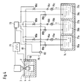
- Fig. 1 is an overall arrangement drawing illustrating an electrical discharge machine as a first embodiment of the present invention.
- Fig. 2 illustrates a relationship between an average machining current and a sludge grain diameter.
- Fig. 3 is an overall arrangement drawing illustrating an electrical discharge machine as a second embodiment of the present invention.
- Fig. 4 is an overall arrangement drawing illustrating an electrical discharge machine as a third embodiment of the present invention.
- Fig. 5 is an overall arrangement drawing illustrating an electrical discharge machine as a fourth embodiment of the present invention.
- Fig. 6 illustrates a relationship between electrical discharge/dwell time and a machining amount.
- Fig. 7 illustrates a relationship between electrical discharge/dwell time and a machining amount.
- Fig. 8 is an overall arrangement drawing illustrating an electrical discharge machine as a fifth embodiment of the present invention.
- Fig. 9 is an overall arrangement drawing illustrating an electrical discharge machine known in the art.
- Fig. 1 is an overall arrangement diagram of an electrical discharge machine illustrating an embodiment of the present invention.
- the numeral 1 indicates a workpiece, 2 an electrode for electrical discharge machining, 3 a dielectric fluid, and 4 a machining tank for storing the dielectric fluid 3.
- a machining tank for storing the dielectric fluid 3.
- 10 indicates sludge produced by electrical discharge machining
- 71 a pulse current generator for supplying an electrical discharge pulse current between the electrode 2 and the workpiece 1
- 72 a storage device acting as sludge grain diameter information outputting unit which stores a relationship between an electrical discharge machining condition, i.e.
- Storage 72 outputs information on the sludge grain diameter corresponding to the electrical discharge machining condition upon the input of the condition.
- 73 indicates a switching device serving as filter selecting unit for switching the filtering path of the dielectric fluid 3 upon receipt of a command from the storage device 72.
- 74 is a dielectric fluid tank, and 75 is a dirty dielectric fluid drawing pipe which runs between the inside of the machining tank 4 and the dielectric fluid tank 74.
- machining conditions i.e., set values attributable to information based on the materials of the electrode 2 and the workpiece 1 or information based on dielectric fluid pressure, are entered beforehand from a CPU or manual input components 82.
- 76a, 76b and 76c indicate dielectric fluid filters provided for the dielectric fluid tank 74.
- the filters are different in filtering accuracy, the accuracy becoming higher in order of filters 76a, 76b and 76c.
- 77a, 77b and 77c are partition plates for sectioning the dielectric fluid tank 74 into independent compartments.
- 78a, 78b and 78c are dirty fluids stored in the independent compartments.
- 79a, 79b and 79c are supply pumps for supplying the dirty fluids 78a, 78b and 78c stored in the independent compartments.
- 80a, 80b and 80c are dielectric fluid path switching solenoid valves for switching the filtering paths of the dirty fluids 78a, 78b and 78c.
- 81 is a clean dielectric fluid supply pipe running between the machining tank 4 inside and the dielectric fluid tank 74.
- Fig. 2 illustrates a relationship between the electrical discharge machining condition (average machining current) and the sludge grain diameter at a time when the electrode 2 is made of copper and the workpieces 1 are made of copper and aluminum alloy.
- the sludge grain diameter is 110 microns when machining is carried out at the average machining current of 100A, 65 microns at 50A, 25 microns at 10A, and 18 microns at 5A.
- the sludge grain diameter is 180 microns at the average machining current of 100A, 90 microns at 50A, 32 microns at 10A, and 25 microns at 5A.
- the above data is generally known and the storage device 72 stores grain diameter data per average machining current on a material-by-material basis.
- the machining conditions such as the electrode 2 and workpiece 1 materials, are input from the input device 82 and the electrical discharge machining condition is input from the pulse generator 71, respectively, to the storage device 72.
- the filter 76a is a paper filter of coarse 50-micron meshes and is low in filtering accuracy
- the filter 76b is a paper filter of 20-micron meshes
- the filter 76c is a paper filter of fine 5-micron meshes and is high in filtering accuracy.
- the switching device 73 acting as the filter selecting unit, switches the filtering path of the dielectric fluid 3 upon receipt of an input from the storage device 72, which stores the grain diameters of the sludge 10 at a time when machining is performed on the electrical discharge machining condition set to the pulse current generator 71.
- the switching device 73 controls the dielectric fluid path switching solenoid valves 80a, 80b and 80c for switching the filtering path so that the dirty dielectric fluid flows into the filter 76a if the grain diameter of the sludge 10 is 50 microns or larger, into the filter 76b if the grain diameter is between 20 microns and less than 50 microns, and into the filter 76c if the grain diameter is less than 20 microns. Accordingly, the filtering is performed most efficiently and dielectric fluid is kept optimally clean for supply into the machining tank 4.
- Dielectric fluid path switching solenoid valves 80a, 80b and 80c for switching the filtering path of the dielectric fluid 3 are provided for the clean dielectric fluid supplying pipe 81 running between the machining tank 4 inside and the dielectric fluid tank 74 and are controlled as described in the aforementioned embodiment.
- the switching apparatus 73 is designed to allow one or more of the solenoid valves 80a, 80b and 80c to be switched, and the two solenoid valves 80a or 80b to be connected in series to provide against the failure of either solenoid valve.
- the single-compartment dielectric fluid tank 74 reduces the installation area and manufacturing costs of the dielectric fluid tank 74.
- Fig. 4 is an overall arrangement diagram of an electrical discharge machine as third embodiment invention, wherein 1 to 4, 10, 71, and 74 to 81 will not be described here because they indicate parts identical or corresponding to those in the overall arrangement diagram of the electrical discharge machine shown in the previous embodiments.
- 83 indicates a detection sensor for detecting the grain diameter of the sludge 10 at a time when machining is conducted on the electrical discharge machining condition set to the pulse current generator 71, and 73 is a switching device acting to select a filter by switching the filtering path of the dielectric fluid 3 upon receipt of an input from the detection sensor 83.
- the filter 76a is a paper filter of coarse 50-micron meshes low in filtering accuracy
- the filter 76b a paper filter of 20-micron meshes
- the filter 76c a paper filter of fine 5-micron meshes high in filtering accuracy.
- the switching device 73 serves to select a filter selecting by switching the filtering path of the dielectric fluid 3 upon receipt of an input from the detection sensor 83.
- the sensor detects the grain diameter of the sludge 10 at a time when machining is carried out under the electrical discharge machining conditions set in the pulse current generator 71.
- the sensor controls the dielectric fluid path switching solenoid valves 80a, 80b and 80c, which switch the filtering path so that the dirty dielectric fluid flows into the filter 76a if the grain diameter of the sludge 10 is 50 microns or larger, into the filter 76b if the grain diameter is between 20 microns and less than 50 microns, and into the filter 76c if the grain diameter is less than 20 microns.
- the dielectric fluid is kept clean and supplied into the machining tank 4 under a variety of machining conditions.
- the storage device 72 shown in the embodiments of Fig. 1 or Fig. 3 may be replaced by the sludge grain detection sensor 83 to produce an effect as described for the third embodiment.
- control can be carried out with further higher accuracy by using the storage device 72 and the sludge grain diameter detection sensor 83 in combination.
- Fig. 5 is an overall arrangement diagram of an electrical discharge machine as a fourth embodiment of the invention, wherein parts identical or corresponding to those in the aforementioned embodiment are designated by identical reference characters and will not be described here.
- 90 indicates a sludge amount storage device for storing the amount of the sludge 10 at a time when machining is done on the electrical discharge machining condition set to the pulse current generator 71.
- 73 is a switching device for switching the filtering path of the dielectric fluid 3 upon receipt of an input from the sludge amount storage device 90.
- Fig. 6 illustrates a relationship between the electrical discharge machining condition and a machining amount at a time when copper is employed for both the electrode 2 and the workpiece 1.
- the machining amount is 1.3 (g/min) as is known.
- Fig. 7 shows the electrical discharge machining condition versus the machining amount at a time when copper is employed for the electrode 2 and aluminum alloy used for the workpiece 1.
- the sludge amount storage device 90 may be provided with machining amount data on an electrical discharge machining condition basis or with parameters on a material-by-material basis, thereby producing an identical effect as in the aforementioned embodiment.
- a plurality of dielectric fluid filters 76 are provided for the dielectric fluid tank 74, and only one is normally employed.
- the amount of the sludge 10 produced when machining is performed under the electrical discharge machining condition set by the pulse current generator 71 is stored into the sludge amount storage device 90.
- a command for switching the filtering path is output to the switching device 73, thereby controlling the dielectric fluid filtering path switching solenoid valves 80a, 80b, 80c and 80d. Therefore, the filtering path is switched automatically and filter replacement can be made without stopping the machine.
- Fig. 8 is an overall arrangement diagram of an electrical discharge machine as a fifth embodiment of the invention, wherein parts identical or corresponding to those in the aforementioned embodiment are indicated by identical reference characters and will not be described here.
- 91 indicates a filter pressure measuring unit, and 73 a switching device for switching the filtering path of the dielectric fluid 3 upon receipt of a command from the filter pressure measuring unit 91.
- the sludge amount storage device 90 may be replaced by filter pressure measuring device 91 to produce an effect as in the fifth embodiment.
- control can be exercised with further higher accuracy by using the sludge amount storage device 90 and the filter pressure measuring device 91 in combination.
Landscapes
- Engineering & Computer Science (AREA)
- Mechanical Engineering (AREA)
- Chemical & Material Sciences (AREA)
- Chemical Kinetics & Catalysis (AREA)
- Electrochemistry (AREA)
- Electrical Discharge Machining, Electrochemical Machining, And Combined Machining (AREA)
Claims (13)
- Elektrische Entladungsbearbeitungsmaschine zum Bearbeiten eines Werkstücks durch Energieversorgung eines Stroms zwischen einer Elektrode und dem Werkstück, die einander in einer dielektrischen Flüssigkeit gegenüber stehen, welche umfaßt:
eine Informationseinrichtung (71, 72, 82, 83, 90, 91) zum Identifizieren zumindest einer Bearbeitungsbedingung, darstellend eine Korngröße oder eine Schlammenge, welche erzeugt werden;
eine Vielzahl von Filtern (76a, 76b, 76c), die in der Filtergenauigkeit verschieden sind, zum Filtern von Schlamm in der dielektrischen Flüssigkeit, der erzeugt wird durch die elektrische Entladungsbearbeitung, gemäß dem Korndurchmesser;
eine Filterauswahleinrichtung (73) zum Auswählen zumindest eines der Filter (76a, 76b, 76c) ansprechend auf die elektrische Entladungsbearbeitungsbedingung, die von der Informationseinrichtung (71, 72, 82, 83, 90, 91) empfangen wird; und
eine Vielzahl von Ventilen (80a, 80b, 80c), die angeordnet sind in einem entsprechenden Flüssigkeitsflußweg mit zumindest einem der Filter (76a, 76b, 76c), und betrieben sind, geöffnet und geschlossen zu werden, durch die Filterauswahleinrichtung (73), um in selektiver Weise den Fluß entlang des Flüssigkeitsflußweges zu steuern;
wobei
die Vielzahl von Fitlern (76a, 76b, 76c) angeordnet ist, eine Vielzahl paralleler Flüssigkeitsfilterwege zu definieren, wobei jeder Weg zumindest einen Filter umfaßt; und
die Filterauswahleinrichtung (73) die Filterwege untereinander umschaltet. - Elektrische Entladungsmaschine nach Anspruch 1, dadurch gekennzeichnet, daß die Bearbeitungsbedingung elektrische Entladungsstromwerte umfaßt.
- Elektrische Entladungsmaschine nach Anspruch 1 oder 2, dadurch gekennzeichnet, daß die Informationseinrichtung umfaßt:
eine Filterdruckerfassungseinrichtung (91) zum Erfassen des Drucks, der angelegt ist an einem ausgewählten Filterweg durch den Schlamm durch die elektrische Entladungsbearbeitung; und
daß die Filterauswahleinrichtung (73) den ausgewählten Filterweg umschaltet auf einen anderen Filterweg in Übereinstimmung mit einem Drucksignal, das von der Filterdruckerfasungseinrichtung (91) eingegeben wird. - Verfahren zum Bearbeiten eines Werkstücks unter einer Vielzahl von Bearbeitungsbedingungen durch Energieversorgung mit einem Strom zwischen einer Elektrode und einem Werkstück, welche einander in einer dielektrischen Flüssigkeit gegenüberstehen, mit den Schritten:
Identifizieren zumindest einer der Bearbeitungsbedingungen, darstellend eine Korngröße oder eine Schlammenge, die erzeugt werden;
automatisches Auswählen der Filterbedingung zum Entfernen des Schlamms aus der dielektrischen Flüssigkeit ansprechend auf den Identifizierungsschritt;
wobei der Auswahlschritt umfaßt:
selektives Filtern des Schlamms in der dielektrischen Flüssigkeit, der durch die elektrische Entladungsbearbeitung erzeugt wird, gemäß der ausgegebenen Filteranforderung; und
Schalten des Flüssigkeitsflusses durch ausgewählte einer Vielzahl von Filtern (76a, 76b, 76c) in Übereinstimmung mit einem erfaßten Drucksignal, wobei die Filter (76a, 76b, 76c) angeordnet sind in parallelen Flüssigkeitsflußwegen, und Umschalten ausgeführt wird von einem Flüssigkeitsweg auf einen anderen. - Verfahren zum Bearbeiten eines Werkstückes nach Anspruch 4, dadurch gekennzeichnet, daß die Bearbeitungsbedingung elektrische Entladungsstromwerte umfaßt.
- Verfahren zum Bearbeiten eines werkstückes nach Anspruch 4 oder 5, dadurch gekennzeichnet, daß der Identifzierungsschritt weiter umfaßt:
Speichern einer Beziehung zwischen der Bearbeitungsbedingung- und Filter-Anforderung für Schlamm, der durch die elektrische Entladungsbearbeitung erzeugt wird; und
Ausgeben von Information der Filteranforderung entsprechend der Bearbeitungsbedingung. - Verfahren zum Bearbeiten eines Werkstückes nach einem der Ansprüch 4 bis 6, dadurch gekennzeichnet, daß die Bearbeitungsbedingung den Korndurchmesser des durch die elektrische Entladungsbearbeitung erzeugten Schlamms umfaßt.
- Verfahren zum Bearbeiten eines Werkstückes nach einem der Ansprüche 4 bis 6, dadurch gekennzeichnet, daß die Bearbeitungsbedindung den Druck umfaßt, der angelegt ist an die Filter (76a, 76b, 76c) durch den Schlamm innerhalb der dielektrischen Flüssigkeit.
- Elektrische Entladungsmaschine nach einem der Ansprüche 1 bis 3, dadurch gekennzeichnet, daß die Informationseinrichtung eine Schlamminformationseinrichtung (72, 80, 90) zum Identifizieren zumindest einer Charakteristik des Schlamms umfaßt.
- Elektrische Entladungsmaschine nach Anspruch 9, dadurch gekennzeichnet, daß die Schlammcharakteristik den Korndurchmesser (72) umfaßt.
- Elektrische Entladungsmaschine nach Anspruch 9, dadurch gekennzeichnet, daß die Schlammcharakteristik die Schlammenge (90) umfaßt.
- Elektrische Entladungsmaschine nach einem der Ansprüche 1 bis 3 und 9 bis 11, dadurch gekennzeichnet, daß die Informationseinrichtung eine Speichereinrichtung (72, 90) mit Einstellwerten, schaltbar auf Information, basierend auf den Materialien von zumindest einem der Elektrode und des Werkstückes, umfaßt.
- Elektrische Entladungsmaschine nach einem der Ansprüch 1 bis 3 und 9 bis 12, dadurch gekennzeichnet, daß die Informationseinrichtung eine Schlammcharakteristik-Erfassungeinrichtung (83) umfaßt.
Applications Claiming Priority (2)
| Application Number | Priority Date | Filing Date | Title |
|---|---|---|---|
| JP2996/92 | 1992-01-10 | ||
| JP4002996A JPH05185325A (ja) | 1992-01-10 | 1992-01-10 | 放電加工装置 |
Publications (2)
| Publication Number | Publication Date |
|---|---|
| EP0550799A1 EP0550799A1 (de) | 1993-07-14 |
| EP0550799B1 true EP0550799B1 (de) | 1995-07-19 |
Family
ID=11544994
Family Applications (1)
| Application Number | Title | Priority Date | Filing Date |
|---|---|---|---|
| EP92117014A Expired - Lifetime EP0550799B1 (de) | 1992-01-10 | 1992-10-06 | Funkerosionsmaschine mit automatischem Filtersystem |
Country Status (4)
| Country | Link |
|---|---|
| US (1) | US5386094A (de) |
| EP (1) | EP0550799B1 (de) |
| JP (1) | JPH05185325A (de) |
| DE (1) | DE69203589T2 (de) |
Families Citing this family (11)
| Publication number | Priority date | Publication date | Assignee | Title |
|---|---|---|---|---|
| JPH0857714A (ja) * | 1994-08-18 | 1996-03-05 | Fanuc Ltd | 放電加工機 |
| JP3528400B2 (ja) * | 1996-03-05 | 2004-05-17 | 三菱電機株式会社 | 放電加工装置および放電加工方法 |
| US6638422B1 (en) | 1999-11-03 | 2003-10-28 | Steven H. Schwartzkopf | Liquid filtration apparatus and method embodying filtration particles having specific gravity less than liquid being filtered |
| JP3572027B2 (ja) * | 2001-03-22 | 2004-09-29 | ファナック株式会社 | ワイヤ放電機の加工液処理装置 |
| JP4490655B2 (ja) * | 2003-06-17 | 2010-06-30 | 株式会社エレニックス | 細穴放電加工装置並びに型彫り・細穴複合放電加工装置および同装置を使用した型彫り・細穴複合放電加工方法 |
| US7270745B2 (en) * | 2003-08-04 | 2007-09-18 | Schwartzkopf Steven H | Liquid filtration apparatus embodying super-buoyant filtration particles |
| JP6298357B2 (ja) * | 2014-05-23 | 2018-03-20 | アマノ株式会社 | 集塵装置 |
| JP6110353B2 (ja) * | 2014-10-06 | 2017-04-05 | ファナック株式会社 | フィルタの交換時期の予測機能を有するワイヤ放電加工機 |
| CN105880764A (zh) * | 2014-12-29 | 2016-08-24 | 北京工商大学 | 一种快走丝线切割机床用金属橡胶过滤系统 |
| CN107186303A (zh) * | 2017-06-28 | 2017-09-22 | 自贡市嘉特数控机械制造有限公司 | 电火花线切割机床工作液的自洁式过滤水箱及过滤方法 |
| JP6391867B1 (ja) * | 2018-02-28 | 2018-09-19 | 株式会社ソディック | 放電加工装置 |
Family Cites Families (11)
| Publication number | Priority date | Publication date | Assignee | Title |
|---|---|---|---|---|
| JPS6013772B2 (ja) * | 1978-08-21 | 1985-04-09 | 三菱電機株式会社 | 放電加工装置 |
| GB2052749A (en) * | 1979-06-12 | 1981-01-28 | El Menshawy | Methods and apparatus for monitoring the condition of dielectric liquid in electric discharge machining |
| JPS5973234A (ja) * | 1982-10-20 | 1984-04-25 | Mitsubishi Electric Corp | 放電加工用加工液の濾過装置 |
| JPS61260934A (ja) * | 1985-05-15 | 1986-11-19 | Mitsubishi Electric Corp | 放電加工機用加工液濾過装置 |
| JPH0626764B2 (ja) * | 1985-07-22 | 1994-04-13 | 株式会社井上ジャパックス研究所 | 放電加工用加工液供給装置 |
| JPS6274527A (ja) * | 1985-09-27 | 1987-04-06 | Mitsubishi Electric Corp | 放電加工方法及びその装置 |
| JPS632621A (ja) * | 1986-06-18 | 1988-01-07 | Fanuc Ltd | ワイヤ放電加工装置における加工液供給方法 |
| JPS6368319A (ja) * | 1986-09-06 | 1988-03-28 | Fanuc Ltd | ワイヤカツト放電加工機の加工液制御機構 |
| JPS63114814A (ja) * | 1986-10-31 | 1988-05-19 | Toyota Motor Corp | 放電加工機の加工液供給装置 |
| EP0303240B1 (de) * | 1987-08-13 | 1994-03-23 | Charmilles Technologies S.A. | Anlage und Verfahren, um in einem ununterbrochenen Versorgungskreis eine Bearbeitungsflüssigkeit zu filtern |
| US5189276A (en) * | 1990-02-13 | 1993-02-23 | Mitsubishi Denki K.K. | Method and apparatus for treating the dielectric used in electrical discharge machining |
-
1992
- 1992-01-10 JP JP4002996A patent/JPH05185325A/ja active Pending
- 1992-10-06 DE DE69203589T patent/DE69203589T2/de not_active Expired - Fee Related
- 1992-10-06 EP EP92117014A patent/EP0550799B1/de not_active Expired - Lifetime
-
1993
- 1993-01-08 US US08/002,414 patent/US5386094A/en not_active Expired - Fee Related
Also Published As
| Publication number | Publication date |
|---|---|
| US5386094A (en) | 1995-01-31 |
| EP0550799A1 (de) | 1993-07-14 |
| DE69203589T2 (de) | 1996-02-08 |
| JPH05185325A (ja) | 1993-07-27 |
| DE69203589D1 (de) | 1995-08-24 |
Similar Documents
| Publication | Publication Date | Title |
|---|---|---|
| EP0550799B1 (de) | Funkerosionsmaschine mit automatischem Filtersystem | |
| KR100229989B1 (ko) | 가공폐액 재생방법 및 가공폐액 재생장치 | |
| US7947917B2 (en) | Wire-cut electric discharge machine having water level abnormality detection function and water level abnormality alarm generation cause specifying method | |
| AU751946B2 (en) | Clean lubricant circulation system | |
| WO1990005040A1 (fr) | Machine a decharge electrique pourvue d'une fonction d'affichage d'informations de commande | |
| DE2825824A1 (de) | Schankanlage und verfahren zum ausschank von kohlensaeurehaltigen getraenken | |
| US5582740A (en) | Machine tool coolant filtering system for segregating different contaminants | |
| EP0286686A1 (de) | Bearbeitungsflüssigkeitsversorgungssteuerungsvorrichtung für drahtschneidefunkenerosionsmaschinen | |
| US7074338B2 (en) | Filtering method and filtering device | |
| DE3924014A1 (de) | Elektroentladungsbearbeitungsvorrichtung | |
| US20040159145A1 (en) | Method and apparatus for measuring a variable in a lubricant/coolant system | |
| US5189276A (en) | Method and apparatus for treating the dielectric used in electrical discharge machining | |
| EP0509130B1 (de) | Zentralschmieranlage | |
| CA1328229C (en) | Apparatus for filtering a reagent | |
| KR20220006344A (ko) | 정수장치 | |
| HK1006869B (en) | Centralized lubrication apparatus | |
| US4895649A (en) | Apparatus for processing coolant | |
| EP0442119B1 (de) | Verfahren und Vorrichtung zum Aufbereiten des dielektrischen Fluids, insbesondere von Funkenerosionsmaschinen | |
| JPS63114814A (ja) | 放電加工機の加工液供給装置 | |
| JP2709670B2 (ja) | 放電加工装置 | |
| JP7311674B1 (ja) | 放電加工機 | |
| JP2002263961A (ja) | ワイヤ放電加工機の加工液タンク | |
| JP3006254B2 (ja) | ワイヤ放電加工機における加工液供給装置 | |
| JPH089126B2 (ja) | 放電加工機の加工液供給装置 | |
| JPH0647624A (ja) | 放電加工装置 |
Legal Events
| Date | Code | Title | Description |
|---|---|---|---|
| PUAI | Public reference made under article 153(3) epc to a published international application that has entered the european phase |
Free format text: ORIGINAL CODE: 0009012 |
|
| AK | Designated contracting states |
Kind code of ref document: A1 Designated state(s): CH DE LI |
|
| 17P | Request for examination filed |
Effective date: 19930728 |
|
| 17Q | First examination report despatched |
Effective date: 19940429 |
|
| GRAA | (expected) grant |
Free format text: ORIGINAL CODE: 0009210 |
|
| AK | Designated contracting states |
Kind code of ref document: B1 Designated state(s): CH DE LI |
|
| REF | Corresponds to: |
Ref document number: 69203589 Country of ref document: DE Date of ref document: 19950824 |
|
| PLBE | No opposition filed within time limit |
Free format text: ORIGINAL CODE: 0009261 |
|
| 26N | No opposition filed | ||
| PGFP | Annual fee paid to national office [announced via postgrant information from national office to epo] |
Ref country code: DE Payment date: 19981012 Year of fee payment: 7 |
|
| PGFP | Annual fee paid to national office [announced via postgrant information from national office to epo] |
Ref country code: CH Payment date: 19981022 Year of fee payment: 7 |
|
| PG25 | Lapsed in a contracting state [announced via postgrant information from national office to epo] |
Ref country code: LI Free format text: LAPSE BECAUSE OF NON-PAYMENT OF DUE FEES Effective date: 19991031 Ref country code: CH Free format text: LAPSE BECAUSE OF NON-PAYMENT OF DUE FEES Effective date: 19991031 |
|
| REG | Reference to a national code |
Ref country code: CH Ref legal event code: PL |
|
| PG25 | Lapsed in a contracting state [announced via postgrant information from national office to epo] |
Ref country code: DE Free format text: LAPSE BECAUSE OF NON-PAYMENT OF DUE FEES Effective date: 20000801 |