EP0551228B1 - Verfahren und Vorrichtung zum Komprimieren einer Rolle aus Fasermatte - Google Patents
Verfahren und Vorrichtung zum Komprimieren einer Rolle aus Fasermatte Download PDFInfo
- Publication number
- EP0551228B1 EP0551228B1 EP93400018A EP93400018A EP0551228B1 EP 0551228 B1 EP0551228 B1 EP 0551228B1 EP 93400018 A EP93400018 A EP 93400018A EP 93400018 A EP93400018 A EP 93400018A EP 0551228 B1 EP0551228 B1 EP 0551228B1
- Authority
- EP
- European Patent Office
- Prior art keywords
- roll
- compressed
- winding
- mat
- winding machine
- Prior art date
- Legal status (The legal status is an assumption and is not a legal conclusion. Google has not performed a legal analysis and makes no representation as to the accuracy of the status listed.)
- Expired - Lifetime
Links
- 239000000835 fiber Substances 0.000 title claims description 14
- 238000000034 method Methods 0.000 title description 5
- 230000006835 compression Effects 0.000 claims abstract description 31
- 238000007906 compression Methods 0.000 claims abstract description 31
- 239000000463 material Substances 0.000 claims abstract description 3
- 238000004804 winding Methods 0.000 claims description 60
- 230000006837 decompression Effects 0.000 claims description 5
- 229920006280 packaging film Polymers 0.000 claims 2
- 239000012785 packaging film Substances 0.000 claims 2
- 239000003292 glue Substances 0.000 claims 1
- 239000002184 metal Substances 0.000 abstract description 3
- 239000002657 fibrous material Substances 0.000 abstract 2
- 230000015572 biosynthetic process Effects 0.000 description 8
- 230000008901 benefit Effects 0.000 description 7
- 238000004519 manufacturing process Methods 0.000 description 7
- 238000004806 packaging method and process Methods 0.000 description 7
- 239000011230 binding agent Substances 0.000 description 6
- 238000003825 pressing Methods 0.000 description 4
- 230000006866 deterioration Effects 0.000 description 3
- 239000002557 mineral fiber Substances 0.000 description 3
- 238000003860 storage Methods 0.000 description 3
- 238000011144 upstream manufacturing Methods 0.000 description 3
- 230000009471 action Effects 0.000 description 2
- 230000015556 catabolic process Effects 0.000 description 2
- 239000011491 glass wool Substances 0.000 description 2
- 230000006872 improvement Effects 0.000 description 2
- 239000011490 mineral wool Substances 0.000 description 2
- 101100491335 Caenorhabditis elegans mat-2 gene Proteins 0.000 description 1
- 101100172886 Caenorhabditis elegans sec-6 gene Proteins 0.000 description 1
- 102100040428 Chitobiosyldiphosphodolichol beta-mannosyltransferase Human genes 0.000 description 1
- 239000004698 Polyethylene Substances 0.000 description 1
- 238000004026 adhesive bonding Methods 0.000 description 1
- 230000008859 change Effects 0.000 description 1
- 230000003750 conditioning effect Effects 0.000 description 1
- 230000007423 decrease Effects 0.000 description 1
- 238000006731 degradation reaction Methods 0.000 description 1
- 230000000593 degrading effect Effects 0.000 description 1
- 239000003365 glass fiber Substances 0.000 description 1
- 230000000977 initiatory effect Effects 0.000 description 1
- 238000009413 insulation Methods 0.000 description 1
- 239000002655 kraft paper Substances 0.000 description 1
- 238000012856 packing Methods 0.000 description 1
- 239000002985 plastic film Substances 0.000 description 1
- 229920006255 plastic film Polymers 0.000 description 1
- -1 polyethylene Polymers 0.000 description 1
- 229920000573 polyethylene Polymers 0.000 description 1
- 239000011148 porous material Substances 0.000 description 1
- 230000002028 premature Effects 0.000 description 1
- 230000037452 priming Effects 0.000 description 1
- 238000011084 recovery Methods 0.000 description 1
- 239000011435 rock Substances 0.000 description 1
- 230000001360 synchronised effect Effects 0.000 description 1
- 210000002268 wool Anatomy 0.000 description 1
Images



Classifications
-
- B—PERFORMING OPERATIONS; TRANSPORTING
- B65—CONVEYING; PACKING; STORING; HANDLING THIN OR FILAMENTARY MATERIAL
- B65H—HANDLING THIN OR FILAMENTARY MATERIAL, e.g. SHEETS, WEBS, CABLES
- B65H18/00—Winding webs
- B65H18/08—Web-winding mechanisms
- B65H18/26—Mechanisms for controlling contact pressure on winding-web package, e.g. for regulating the quantity of air between web layers
-
- B—PERFORMING OPERATIONS; TRANSPORTING
- B65—CONVEYING; PACKING; STORING; HANDLING THIN OR FILAMENTARY MATERIAL
- B65B—MACHINES, APPARATUS OR DEVICES FOR, OR METHODS OF, PACKAGING ARTICLES OR MATERIALS; UNPACKING
- B65B63/00—Auxiliary devices, not otherwise provided for, for operating on articles or materials to be packaged
- B65B63/02—Auxiliary devices, not otherwise provided for, for operating on articles or materials to be packaged for compressing or compacting articles or materials prior to wrapping or insertion in containers or receptacles
- B65B63/024—Auxiliary devices, not otherwise provided for, for operating on articles or materials to be packaged for compressing or compacting articles or materials prior to wrapping or insertion in containers or receptacles for compressing by winding
-
- B—PERFORMING OPERATIONS; TRANSPORTING
- B65—CONVEYING; PACKING; STORING; HANDLING THIN OR FILAMENTARY MATERIAL
- B65H—HANDLING THIN OR FILAMENTARY MATERIAL, e.g. SHEETS, WEBS, CABLES
- B65H19/00—Changing the web roll
- B65H19/22—Changing the web roll in winding mechanisms or in connection with winding operations
- B65H19/2276—The web roll being driven by a winding mechanism of the coreless type
-
- B—PERFORMING OPERATIONS; TRANSPORTING
- B65—CONVEYING; PACKING; STORING; HANDLING THIN OR FILAMENTARY MATERIAL
- B65H—HANDLING THIN OR FILAMENTARY MATERIAL, e.g. SHEETS, WEBS, CABLES
- B65H2301/00—Handling processes for sheets or webs
- B65H2301/40—Type of handling process
- B65H2301/41—Winding, unwinding
- B65H2301/413—Supporting web roll
- B65H2301/4137—Supporting web roll on its outer circumference
- B65H2301/4138—Supporting web roll on its outer circumference belt arrangement
-
- B—PERFORMING OPERATIONS; TRANSPORTING
- B65—CONVEYING; PACKING; STORING; HANDLING THIN OR FILAMENTARY MATERIAL
- B65H—HANDLING THIN OR FILAMENTARY MATERIAL, e.g. SHEETS, WEBS, CABLES
- B65H2701/00—Handled material; Storage means
- B65H2701/10—Handled articles or webs
- B65H2701/17—Nature of material
- B65H2701/177—Fibrous or compressible material
-
- B—PERFORMING OPERATIONS; TRANSPORTING
- B65—CONVEYING; PACKING; STORING; HANDLING THIN OR FILAMENTARY MATERIAL
- B65H—HANDLING THIN OR FILAMENTARY MATERIAL, e.g. SHEETS, WEBS, CABLES
- B65H2701/00—Handled material; Storage means
- B65H2701/10—Handled articles or webs
- B65H2701/19—Specific article or web
- B65H2701/1922—Specific article or web for covering surfaces such as carpets, roads, roofs or walls
-
- B—PERFORMING OPERATIONS; TRANSPORTING
- B65—CONVEYING; PACKING; STORING; HANDLING THIN OR FILAMENTARY MATERIAL
- B65H—HANDLING THIN OR FILAMENTARY MATERIAL, e.g. SHEETS, WEBS, CABLES
- B65H2801/00—Application field
- B65H2801/81—Packaging machines
Definitions
- the invention relates to techniques for compressing and then winding fibrous mats to allow their wrapping and conditioning up to their place of use.
- Flexible fibrous mattresses in particular those made of glass wool or rock wool intended for insulation, are most often wound on themselves very tightly to prevent them from occupying too much volume important during their transport. The higher the compression ratio of the fibrous mat, the cheaper the transport and storage.
- the production lines operate continuously and deliver mattresses of uninterrupted length. These are cut to form rolls whose width and length correspond to the needs of the user. On the production lines of insulating wool mattresses there are winders whose operation is more or less automated.
- these machines To perform their functions, these machines must have a number of basic characteristics. They must compress the woolen mattresses as much as possible and this in the same way over their entire length but they must also avoid damaging the fiber and the binder which constitute the insulating mattress.
- One mission that the invention sets itself is precisely to provide a winder whose downtime is reduced to a minimum.
- An object of the invention is to provide fibrous mattresses wound on themselves with high compression ratios and which find all their original characteristics on decompression.
- An object of the invention is also to provide a winder which in no way degrades the fibers and the binder of the fibrous mat during compression.
- the rolls of mineral fiber mattresses which it is possible to obtain with the rewinders of the prior art are limited in the case of specific masses of 8 to 10 kg / m3, at compression rates of less than 7/1 if the compression is carried out in a single operation and at rates of between 6 and 8/1 with the methods comprising two mechanical steps or a mechanical step and a vacuum step.
- a winder of the first type is described for example in patent EP 294 290. It comprises two flat conveyor belts associated to form a dihedral which is in permanently tangent to the fibrous roller in formation. The compression of the fibrous mattress is exerted by a movable roller whose position and speed of rotation obey precise laws.
- This type of winder has two types of drawbacks. First of all, the pressure is exerted on the fibrous roller in formation only in well-defined places. Between these compression zones, the fibrous mat relaxes to be compressed again a little further. This alternation of pressure / depression on the fibers can cause them to break and moreover the binder which associates the fibers with one another undergoes fatigue which can cause its deterioration in places.
- the second drawback of this type of winder lies in their discontinuous operation. At the end of the winding operation of a first fibrous roller, the pressure roller must be spread so as to allow the ejection of the fibrous roller and it is only after its return that the following priming operation of the winding of a new fibrous roll can take place.
- a second type of winder has been developed. He uses to press on the fibrous roller either a free mat or two groups of belts which form a sort of circular cavity around the roller.
- the invention relates to a roll of compressed insulating mattress based on mineral fibers and a specific mass at the origin of 8 to 10 kg / m3, the compression ratio of which is at least 8.5 to 1.
- the subject of the invention is therefore a winder for winding a flexible band around itself and in which the roller in formation is rotated by two flexible means which each enclose a part of the circumference of the roller in formation and which are guided and driven by appropriate means in order to adapt to the magnification of said roller in formation (see US-A-4,034,928).
- the flexible strip is a fibrous mattress compressed by compression means before winding, and the flexible means are carpets which encircle one substantially half the circumference of the forming roller and the other a substantial part of the remaining half.
- the subject of the invention is also the rolls of compressed insulating mattresses based on mineral fibers obtained by this type of winder, and in particular having a compression ratio of at least 8.5 to 1.
- the evacuation of the roll of the compressed mattress is carried out in the same direction as the introduction of the compressed fibrous mattress.
- the compressed fibrous mattress is obtained by compression without sliding of the fibrous mat between pressing members which are preferably between two conveyor belts.
- a device such as a metal plate keeps the fibrous mat compressed between its exit from the pressing members and its contact with the preceding turn of the roll in formation.
- the compressed mattress is introduced substantially tangentially to the periphery of the roller being formed.
- At least three of the four rollers which guide the two belts are tangent to a cylinder whose director has substantially the shape of a spiral corresponding to the theoretical envelope of the compressed roller. at the same time.
- two of the four preceding rollers, located downstream of the machine are replaced - at the moment when they release the finished roll - by two new rollers whose progression is carried out in the same direction as the downstream rollers.
- the four rollers are associated two by two with rotating systems of the carousel type which support them.
- the fibrous mattress roll of the invention with high compression ratio allows significant savings to be made during the transport and storage of the insulating blankets.
- the technique of the invention makes it possible to exercise weighting the winding at a constant pressure both in time and in space, thus avoiding the back and forth compression and depression which degrade the fibers and cause fatigue of the binder.
- the fact of passing the device according to the invention through the fibrous roller rather than exerting a back and forth movement also makes it possible to reduce downtime very significantly.
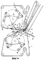
- Figure 1 we see the essential elements of the device of the invention.
- a first conveyor belt whose conformation varies throughout the winding operation. It is the same for the second conveyor belt 2.
- the support rollers have been shown with circles around their axes. treadmills, the position of which does not change during the entire winding operation.
- the rollers whose axes are represented by crosses in broken lines have their position which changes during the duration of the winding of the fibrous mat.
- the two plane elements 5 and 6 move at substantially the same speed which is the speed of exit of the mattress fibrous 4 of the production line.
- This part of the device therefore makes it possible to avoid any relative movement between the fibrous mattress and therefore the fibers of the fibrous mattress on the one hand and the carpets which compress them, on the other. This avoids everything friction which would risk damaging said fibers.
- the flat part 5 of the treadmill 1 is actually supported by a second treadmill 8, the upper part of which supports the straight part 5 of the treadmill over its entire length. It is advantageous to use this conveyor belt 8 not only to support the treadmill 1 but also to train it in its translational movement.
- the roller 9 is therefore advantageously used to drive both the conveyor belt 8 and the conveyor belt 1.
- the rotational movement of this roller 9 has a constant speed during winding.
- the conveyor belt 2 it is driven by one of its support rollers upstream of the cavity, for example the roller 10. Its speed is also constant during the winding.
- the tension of the conveyor belts 1 and 2 is provided respectively by the roller 11 and by the roller 12, the position of which is controlled by the central computer at all times.
- the cavity in which the compressed fibrous mat is rolled up is defined by five rollers and two conveyor belt elements. Among the two rollers are fixed: the roller 9 which has already been discussed and the 13 which guides the treadmill 2.
- the rollers 14 and 15 respective supports of the treadmills 1 and 2 move in two paths parallel rectilinear so as to release a length of mat respectively 17 for the mat 1 and 18 for the mat 2 which will serve to form the circular wall of the cavity where the compressed mattress will be rolled up.
- the small movable roller 16 exerts a particular function at the start of the operation.
- the roller 16 occupies a position which allows the end of the mattress 19 to penetrate very far into the cavity. This position is determined by the thickness of the mattress to be rolled up.
- the purpose of the roller 16 is to close the cavity at the start of winding and to allow the formation of the first turn.
- the position of the roller 16 is fixed.
- the rollers 14 and 15 begin to move to the left of the figure in the direction of the roller 10 and its twin roller 20.
- This movement is also managed by the computer so that the four rollers 9, 14, 15 and 13 occupy the theoretical position at the periphery of the compressed fibrous mattress, that is to say that they are tangent to a cylinder with a spiral director.
- the computer calculates the theoretical dimension to be given to the cylinder with spiral director which constitutes the periphery of the compressed roller. This dimension depends on the one hand on the compression coefficient which it was decided to apply to the mattress, therefore finally on its thickness in the compressed state and on the other hand on the length of mattress already rolled up.
- the rollers 9 and 13 being fixed, it is the position of the rollers 14 and 15 which defines the cylinder in question, the length of the curved walls 17 and 18 of the cavity being defined by the position of the tensioning rollers 11 and 12, determined it - even by computer.
- the packaging of the compressed roll is carried out simultaneously with the winding of the last turn of compressed mattress.
- the same materials as usual are used for packaging, such as kraft paper, plastic films, for example polyethylene.
- the strips of film intended to package the products are pre-cut and pre-glued.
- the next step is to eject the wrapped roll. It is shown in Figure 3 where we see a general movement of the carpet 1 driven by the roller 20 which was hitherto stationary and which this time moves down to free the passage to the compressed and packaged roller 23 which occupies the position 24 on the conveyor 25 which discharges it. As soon as the roller 23 has left the reel, the belt 1 driven by the roller 20 comes back to the position it occupied at the start of the operation in FIG. 1. The rollers 14 and 15 also come in their original position and the operation can start again immediately. It is thus seen that the dead time which separates the end of the winding of a first roll and the start of the winding of the next roll is very reduced since in the device represented in FIGS. 1, 2 and 3 it suffices that roller 20 moves away from roller 10 and then returns to its original position while rollers 14 and 15 also make the return journey. This can be done in fractions of a second.
- FIG. 4 and FIG. 5 show a variant of the invention which uses two carousels, respectively 26 and 27, to obtain the movements of the support rollers for the belts 1 and 2.
- Each of these carousels has two cheeks between which are fixed. rollers which will in turn support the belts 1 and 2.
- Each of the carousels' cheeks has three radial arms located at 120 ° from each other. At the ends of these arms are fixed levers which in turn carry at their ends the rollers which support the belts 1 and 2. The levers deviate more or less from the axis of the carousels by means of jacks. Only one of the three rollers on each carousel is active at any given time. In the figure these are the rollers 28 and 29.
- rollers 28 and 29 are supported respectively by the levers 30 and 31, actuated by the jacks 32 and 33, and themselves supported by the radial arms 34 and 35.
- the function and the movement of the rollers 28 and 29 is exactly the same as that of the rollers 14 and 15 of FIG. 1.
- the two carousels 26 and 27 are driven in a synchronous movement but their speed is not constant. It is such that, as before, the rollers 9, 13, 28 and 29 are in a position such that the belts 1, 2 constitute the theoretical figure which defines the compression of the fibrous mattress wound on itself. If the rollers are of small diameter, they can be all four tangent to this theoretical figure otherwise, as in the figure, only three are.
- the driving rollers are the roller 9 for the belt 1, the roller 39 for the conveyor belt 7, and the roller 38 for the belt 2.
- the speed of these three rollers is constant, as for the rotational speed of the two carousels and the position of the two jacks 32, 33 and so on that the position of the tension rollers 11 and 12 is determined by the central computer of the device.
- FIGS. 4 and 5 therefore has the advantage of allowing two pairs of rollers 36 and 37 to succeed immediately without dead time the rollers 28 and 29 which have just escaped from the other side.
- a device which makes it possible to maintain the pressure on the compressed mattress between the place where it leaves the upper presser belt 7 and the place where contact with the previous turn 41 is established. It is for example a metal plate supported by a flange which passes between the rollers 39 and 13.
- the table presents the results obtained.
- the most spectacular progression concerns time packaging, this is due to the fact that the reel of the invention performs it in masked time, in other words the packaging is carried out at the same time as the winding of the last turn of the compressed mattress.
- the compressed roller of the invention with for the first time, compression ratios higher than 10/1 obtained directly on the rewinder without deterioration of the mattress which regains its thickness and its original qualities present compared to the rollers of the prior art the advantage of savings on packaging, transport and storage.
- the reduced downtime of the machine, object of the invention makes it possible to reduce the necessary ratio between line speed and winding speed.
- This ratio was so far from 2 to 2.5 and it decreases to 1.3-1.5 on the new machine.
- This allows either to wind a given product for a given line speed at a lower winding speed and therefore further improve the quality of the winding, or to wind a given product at a winding speed (which can reach 200 m / min) higher than the maximum speed allowed so far (150 m / min). This saves on investment.
Landscapes
- Engineering & Computer Science (AREA)
- Mechanical Engineering (AREA)
- Preliminary Treatment Of Fibers (AREA)
- Storage Of Harvested Produce (AREA)
- Winding Of Webs (AREA)
- Auxiliary Devices For And Details Of Packaging Control (AREA)
- Nonwoven Fabrics (AREA)
- Compression, Expansion, Code Conversion, And Decoders (AREA)
- Devices For Executing Special Programs (AREA)
Claims (14)
- Wickelmaschine zum Aufwickeln einer weichen Bahn (19) auf sich selbst, bei der die in Bildung begriffene Rolle von zwei flexiblen Einrichtungen (17, 18) drehend mitgenommen wird, welche jeweils einen Teil des Umfangs der in Bildung begriffenen Rolle eng umschließen und von Einrichtungen geführt und angetrieben sind, welche dazu ausgelegt sind, sich an die Größenzunahme der in Bildung begriffenen Rolle anzupassen,
dadurch gekennzeichnet, daß
die weiche Bahn (19) eine Fasermatte ist, die vor dem Aufwickeln von Komprimiereinrichtungen (5, 6) komprimiert wird, und
die flexiblen Einrichtungen (17, 18) Bänder sind, von denen das eine im wesentlichen die Hälfte des Umfangs der in Bildung begriffenen Rolle und das andere einen wesentlichen Teil der verbleibenden Hälfte eng umschließt. - Wickelmaschine nach Anspruch 1, dadurch gekennzeichnet, daß die Ausgabe der Rolle (23) der komprimierten Matte in der gleichen Richtung wie die Einführung der komprimierten Fasermatte (19) in die Wickelmaschine mittels eines Bandes (1) stattfindet, welches von einer Rolle (20) angetrieben ist, die sich nach unten bewegt, um den Weg für die komprimierte Rolle freizugeben.
- Wickelmaschine nach Anspruch 2, dadurch gekennzeichnet, daß die komprimierte Fasermatte (19) durch schlupffreies Komprimieren der Fasermatte (4) zwischen Komprimiereinrichtungen, insbesondere zwischen Förderbändern (5, 6), hergestellt wird.
- Wickelmaschine nach Anspruch 3, dadurch gekennzeichnet, daß eine Vorrichtung wie etwa eine Metallplatte (40) die Fasermatte (19) zwischen ihrem Austritt aus den Komprimiereinrichtungen (5, 6) und ihrer Anlage an die vorhergehende Windung (41) der in Bildung begriffenen Rolle komprimiert hält.
- Wickelmaschine nach einem der vorhergehenden Ansprüche, dadurch gekennzeichnet, daß die komprimierte Matte (19) im wesentlichen tangential zum Umfang der in Bildung begriffenen Rolle (42) eingeführt wird.
- Wickelmaschine nach einem der vorhergehenden Ansprüche, dadurch gekennzeichnet, daß die Bänder (17, 18), welche die in Bildung begriffene Rolle eng umschließen, von vier Rollen geführt sind, von denen zwei (9, 13) ortsfest und zwei (14, 15; 28, 29) verfahrbar sind.
- Wickelmaschine nach Anspruch 6, dadurch gekennzeichnet, daß eine fünfte Rolle (16) den Beginn des Aufwickelns erleichtert und bei diesem mitwirkt, indem sie eine Stellung einnimmt, welche es dem Ende der weichen Bahn (19) gestattet, weit nach vorne in den von den Bändern (17, 18) gebildeten Hohlraum einzudringen.
- Wickelmaschine nach Anspruch 6 oder 7, dadurch gekennzeichnet, daß zu einem gegebenen Zeitpunkt mindestens drei der vier Rollen einen Zylinder tangieren, dessen Leitlinie im wesentlichen die Form einer Spirale hat, welche der theoretischen Umhüllenden der komprimierten Rolle zum gleichen Zeitpunkt entspricht.
- Wickelmaschine nach einem der vorhergehenden Ansprüche, dadurch gekennzeichnet, daß eine Verpackungsfolie mittels einer Aufgabevorrichtung gleichzeitig mit der letzten Windung der Rolle der komprimierten Matte aufgewickelt wird.
- Wickelmaschine nach Anspruch 9, dadurch gekennzeichnet, daß die Verpackungsfolie eine größere Länge als die Abwicklung der letzten Windung der Rolle der komprimierten Matte hat, und daß sie auf ihrer Innenfläche an ihren beiden Enden mit Klebstoff versehen ist.
- Wickelmaschine nach Anspruch 7, dadurch gekennzeichnet, daß verfahrbare Rollen (28, 29, 36, 37) paarweise drehenden Systemen vom Typ eines Karussels zugeordnet sind, welche diese tragen.
- Wickelmaschine nach Anspruch 7 oder 11, dadurch gekennzeichnet, daß am Ende des Aufwickelns, wenn die beiden in Produktionsrichtung hinteren verfahrbaren Rollen (28, 29) die Rolle der komprimierten hatte (19) freigeben, zwei neue verfahrbare Rollen (36, 37) unverzüglich in Stellung gebracht werden und daß ihr Fortschreiten in der gleichen Richtung wie derjenigen der hinteren Rollen stattfindet.
- Wickelmaschine nach einem der Ansprüche 2 bis 10, dadurch gekennzeichnet, daß der Antrieb des einen Bandes (1) von einem Transportband (8) durchgeführt wird, welches es trägt.
- Rolle aus komprimierter Dämmatte auf Basis von Mineralfasern, hergestellt mit der Wickelmaschine nach einem der vorhergehenden Ansprüche, mit einer ursprünglichen spezifischen hasse von 8 bis 10 kg/m³, und welche in der Lage ist, ihre Eigenschaften nach Dekompression wiederzuerlangen, dadurch gekennzeichnet, daß ihr Kompressionsverhältnis mindestens 8,5:1 beträgt.
Applications Claiming Priority (2)
| Application Number | Priority Date | Filing Date | Title |
|---|---|---|---|
| FR9200064A FR2685904A1 (fr) | 1992-01-07 | 1992-01-07 | Rouleau de matelas fibreux comprime, methode et dispositif pour l'obtenir. |
| FR9200064 | 1992-01-07 |
Publications (2)
| Publication Number | Publication Date |
|---|---|
| EP0551228A1 EP0551228A1 (de) | 1993-07-14 |
| EP0551228B1 true EP0551228B1 (de) | 1996-04-10 |
Family
ID=9425424
Family Applications (1)
| Application Number | Title | Priority Date | Filing Date |
|---|---|---|---|
| EP93400018A Expired - Lifetime EP0551228B1 (de) | 1992-01-07 | 1993-01-07 | Verfahren und Vorrichtung zum Komprimieren einer Rolle aus Fasermatte |
Country Status (22)
| Country | Link |
|---|---|
| US (1) | US5425512A (de) |
| EP (1) | EP0551228B1 (de) |
| JP (1) | JPH05330705A (de) |
| KR (1) | KR930016330A (de) |
| AT (1) | ATE136515T1 (de) |
| AU (1) | AU661356B2 (de) |
| BR (1) | BR9300020A (de) |
| CA (1) | CA2086817A1 (de) |
| CZ (1) | CZ286700B6 (de) |
| DE (1) | DE69302101T2 (de) |
| DK (1) | DK0551228T3 (de) |
| ES (1) | ES2087667T3 (de) |
| FI (1) | FI101062B (de) |
| FR (1) | FR2685904A1 (de) |
| HU (1) | HU214763B (de) |
| NO (1) | NO305392B1 (de) |
| NZ (1) | NZ245580A (de) |
| PL (1) | PL170908B1 (de) |
| SI (1) | SI9300008B (de) |
| SK (1) | SK279483B6 (de) |
| TR (1) | TR27519A (de) |
| ZA (1) | ZA9210099B (de) |
Cited By (1)
| Publication number | Priority date | Publication date | Assignee | Title |
|---|---|---|---|---|
| DE102015112142A1 (de) | 2015-07-24 | 2017-01-26 | Saint-Gobain Isover G+H Ag | Verfahren zum Vorbereiten einer Dämmstoffbahn für den Transport und Vorrichtung zum Durchführen des Verfahrens |
Families Citing this family (42)
| Publication number | Priority date | Publication date | Assignee | Title |
|---|---|---|---|---|
| DE10152385B4 (de) * | 2001-10-24 | 2012-11-22 | Saint-Gobain Isover G+H Ag | Großgebinde aus mehreren jeweils zu einer Rolle gewickelten, folienverpackten Dämmstoffbahnen aus Mineralwolle, insbesondere Glaswolle |
| US5832696A (en) * | 1994-09-21 | 1998-11-10 | Owens Corning Fiberglas Technology, Inc. | Method and apparatus for packaging compressible insulation material |
| FR2731687B1 (fr) * | 1995-03-17 | 1997-04-25 | Tictor Sa | Dispositif enrouleur pour la formation d'un rouleau fibreux comprime |
| ZA963563B (en) * | 1995-05-15 | 1996-11-19 | Saint Gobain Isover | Process and device for compressing and packaging compressible products |
| FI100049B (fi) * | 1995-06-14 | 1997-09-15 | Espe Oy | Menetelmä ja laitteisto avosolumuovin pakkaamiseksi |
| DE19536750C2 (de) * | 1995-10-02 | 1998-11-05 | Friatec Rpp Gmbh System Altvat | Rundballenpresse für Müll und Müllverpackungsanlage mit einer derartigen Rundballenpresse |
| IT1281197B1 (it) * | 1995-12-04 | 1998-02-17 | Politex Spa | Macchina per la formazione di rotoli di ovatta di forma compatta |
| DE29604901U1 (de) * | 1996-03-16 | 1996-05-15 | Kaibel & Sieber GmbH, 67547 Worms | Vorrichtung zum Wickeln einer Bahn aus verdichtbarem Material |
| ZA981514B (en) * | 1997-03-07 | 1998-08-28 | Saint Gobain Isover | Winding machine for fibrous mats |
| DE69831633T2 (de) * | 1997-07-25 | 2006-06-14 | Noritsu Koki Co Ltd | Filmmagazin zum Speichern geschnittener Streifen photographischen Films |
| EP0908400A1 (de) | 1997-10-13 | 1999-04-14 | Rockwool International A/S | Verpackung für Produkte aus Mineralwolle |
| DE59803801D1 (de) * | 1998-07-24 | 2008-10-02 | Rpp International Ltd | Rundballenpresse und verfahren zum verpressen von müll |
| EP1026302B1 (de) * | 1999-02-03 | 2004-03-24 | Deutsche Rockwool Mineralwoll GmbH & Co. OHG | Vorrichtung zum Aufwickeln eines Faservlieses |
| ES2190649T3 (es) | 1999-04-23 | 2003-08-01 | Rpp International Ltd | Procedimiento para envolver un fardo redondo prensado en una prensa empacadora, dispositivo de envoltura en una lamina y prensa empacadora con un dispositivo de envoltura de esta clase con una lamina. |
| AU6928500A (en) * | 1999-08-31 | 2001-03-26 | Neighbor, Todd W. | Roll of insulation material and method of wrapping a roll of insulation material |
| US6321507B1 (en) * | 1999-10-29 | 2001-11-27 | Owens Corning Fiberglas Technology, Inc. | Apparatus for packaging insulation material |
| FR2809119A1 (fr) * | 2000-05-17 | 2001-11-23 | Saint Gobain Isover | Procede de formation et conditionnement de feutres isolants et son dispositif de mise en oeuvre |
| US6641080B2 (en) * | 2001-12-28 | 2003-11-04 | Kimberly-Clark Worldwide, Inc. | Method and apparatus for winding a web |
| US6866213B2 (en) | 2001-12-28 | 2005-03-15 | Kimberely-Clark, Worldwide, Inc. | Rolled web products having a web wound in an oscillating fashion |
| AT411255B (de) * | 2002-07-16 | 2003-11-25 | Saint Gobain Isover Austria Ag | Verfahren und vorrichtung zum aufwickeln von elastisch komprimierbaren platten |
| US20040050988A1 (en) * | 2002-09-12 | 2004-03-18 | Kt Industries Llc | Method and apparatus for packing material under compression and the package made thereby |
| US6887343B2 (en) * | 2002-12-20 | 2005-05-03 | Fleetguard, Inc. | Filter coating, winding, finishing and manufacturing system |
| US7100862B2 (en) | 2003-09-03 | 2006-09-05 | Ottawa Fibre, Inc. | Roll-up machine and method |
| GB0324942D0 (en) * | 2003-10-25 | 2003-11-26 | Creo Products Ltd | Baling apparatus and method |
| WO2006032154A1 (de) * | 2004-09-21 | 2006-03-30 | Strahm Textile Systems Ag | Vorrichtung zum unterbrechungsfreien aufwickeln einer kontinuierlich zugeförderten textilen warenbahn |
| EP1645532A1 (de) * | 2004-10-09 | 2006-04-12 | Deutsche Rockwool Mineralwoll GmbH & Co. OHG | Verfahren und Vorrichtung zur Herstellung eines Wickels aus einem Faservlies |
| FI122646B (fi) * | 2007-11-28 | 2012-05-15 | Paroc Oy Ab | Menetelmä ja laite mineraalivillarullien muodostamiseksi |
| US8177155B2 (en) * | 2009-12-09 | 2012-05-15 | Aaf-Mcquay Inc. | Apparatus and method for compressing and winding overlapped fibrous blankets |
| FR2991301B1 (fr) * | 2012-06-04 | 2014-05-23 | Saint Gobain Isover | Dispositif enrouleur |
| US9884694B2 (en) | 2012-09-19 | 2018-02-06 | Mat Processing, Llc | Rear discharge mat rolling machine with wrapper |
| US9868605B2 (en) * | 2014-02-12 | 2018-01-16 | Andrew L. Bishop | Geotextile rolling apparatus |
| EP3115324A1 (de) * | 2015-07-06 | 2017-01-11 | Qubiqa Esbjerg A/S | Verfahren und vorrichtung zur herstellung von rollen aus flexiblem material wie mineralwolle |
| CN105752423B (zh) * | 2016-04-07 | 2018-03-06 | 河南省科琦游乐设备有限公司 | 腹带移动式无芯卷包机 |
| DE102017113532A1 (de) * | 2017-06-20 | 2018-12-20 | Storopack Hans Reichenecker Gmbh | Vorrichtung zur Bereitstellung eines spulenförmigen Polsterungsprodukts für Verpackungszwecke |
| CN107867454A (zh) * | 2017-12-14 | 2018-04-03 | 新疆亿支特机械设备制造有限公司 | 一种海绵压缩卷包机 |
| DE102019103498A1 (de) | 2019-02-12 | 2020-08-13 | Saint-Gobain Isover G+H Ag | Verfahren und Vorrichtung zum Herstellen einer Rohrschale aus einem isolierenden Material |
| DE102019135610A1 (de) | 2019-12-20 | 2021-06-24 | Sprick Gmbh Bielefelder Papier- Und Wellpappenwerke & Co. | Vorrichtung und Verfahren zum Verarbeiten eines Polstermaterialstrangs und Polstermaterialwicklung |
| CN111251644A (zh) * | 2020-03-17 | 2020-06-09 | 吉林联科特种石墨材料有限公司 | 一种硬质碳纤维保温材料成型设备 |
| CA3196818A1 (en) | 2020-09-28 | 2022-03-31 | C3 Corporation | Paper wrapping materials and method for a highly compressed product |
| US11787655B2 (en) | 2020-09-28 | 2023-10-17 | C3 Corporation | Variable roll cage machine and process |
| CZ309273B6 (cs) * | 2020-12-30 | 2022-07-13 | Asipo s.r.o | Zařízení pro výrobu rohoží z rostlinných materiálů |
| EP4603401A1 (de) * | 2024-02-14 | 2025-08-20 | FillMatic Polsterindustriemaschinen GmbH | Verpackungsmaschine |
Family Cites Families (23)
| Publication number | Priority date | Publication date | Assignee | Title |
|---|---|---|---|---|
| US546009A (en) * | 1895-09-10 | John w | ||
| US2057191A (en) * | 1931-08-27 | 1936-10-13 | Kenneth W Huffine | Roll forming device |
| BE500783A (de) * | 1950-01-23 | |||
| DE974995C (de) * | 1951-09-29 | 1961-07-13 | Caspar Dipl-Ing Dott | Vorrichtung zum selbsttaetigen Abmessen, Abtrennen und kernlosen Aufwickeln von endlosen Werkstoff-, insbesondere Papierbahnen |
| GB724321A (en) * | 1952-03-29 | 1955-02-16 | Johnson & Johnson | Apparatus for winding limp material into coreless rolls |
| US2775410A (en) * | 1952-03-29 | 1956-12-25 | Johnson & Johnson | Apparatus for winding limp material into coreless rolls |
| DE1295304B (de) * | 1963-07-29 | 1969-05-14 | Lee Kennth Philip | Aufrollvorrichtung zum Aufwickeln von Bahnmaterial ohne Wickeltraeger |
| US4022003A (en) * | 1976-02-09 | 1977-05-10 | Sperry Rand Corporation | Controlling the size of a roll core formed in a crop material roll forming machine |
| US4034928A (en) * | 1976-06-29 | 1977-07-12 | Union Carbide Corporation | Method and apparatus for producing coreless roll assemblies of separable bags |
| US4114530A (en) * | 1977-06-23 | 1978-09-19 | Owens-Corning Fiberglas Corporation | Apparatus for packaging compressible strips |
| US4164177A (en) * | 1978-09-07 | 1979-08-14 | Owens-Corning Fiberglas Corporation | Methods and apparatus for rolling material into a package |
| US4365767A (en) * | 1981-02-02 | 1982-12-28 | Benthimere Floyd D | Apparatus for laminating and coiling insulation blankets |
| DE3128155A1 (de) * | 1981-07-16 | 1983-02-03 | Christian Maier GmbH & Co Maschinenfabrik, 7920 Heidenheim | Aufwickelvorrichtung fuer bahnfoermiges gut zur herstellung von wickelrollen ohne wickelkern. |
| FR2553744B1 (fr) * | 1983-10-21 | 1986-03-28 | Saint Gobain Isover | Enrouleuse a compression asservie |
| US4602471A (en) * | 1985-05-28 | 1986-07-29 | Owens-Corning Fiberglas Corporation | Roll-up method and apparatus for mineral fiber pack |
| FR2583498B1 (fr) * | 1985-06-14 | 1987-08-07 | Saint Gobain Isover | Procede et dispositif de fabrication de coquilles en fibres minerales |
| US4653397A (en) * | 1985-07-30 | 1987-03-31 | Owens-Corning Fiberglas Corporation | Apparatus for packaging insulation material |
| JPH0613380B2 (ja) * | 1985-08-02 | 1994-02-23 | 産栄機設株式会社 | 巻取圧縮方法およびその装置 |
| FR2616137B1 (fr) * | 1987-06-03 | 1990-08-03 | Saint Gobain Isover | Perfectionnements aux enrouleuses a compression de bandes de materiaux compressibles |
| DE8802337U1 (de) * | 1988-02-23 | 1989-06-22 | P.J. Zweegers en Zonen, Landbouwmachinefabriek B.V., Geldrop | Rundballenpresse |
| US4973010A (en) * | 1989-03-01 | 1990-11-27 | Production Design Products, Inc. | Carpet rolling machine |
| US5022597A (en) * | 1989-09-27 | 1991-06-11 | Krantz America, Inc. | Sheet winding apparatus |
| FR2663049B1 (fr) * | 1990-06-12 | 1994-05-13 | Isover Saint Gobain | Recyclage de produits fibreux dans une ligne de production de matelas a partir de fibres. |
-
1992
- 1992-01-07 FR FR9200064A patent/FR2685904A1/fr active Pending
- 1992-12-22 AU AU30331/92A patent/AU661356B2/en not_active Ceased
- 1992-12-23 NZ NZ245580A patent/NZ245580A/en unknown
- 1992-12-30 CZ CS19924002A patent/CZ286700B6/cs not_active IP Right Cessation
- 1992-12-30 SK SK4002-92A patent/SK279483B6/sk unknown
- 1992-12-30 ZA ZA9210099A patent/ZA9210099B/xx unknown
-
1993
- 1993-01-05 NO NO930015A patent/NO305392B1/no not_active IP Right Cessation
- 1993-01-05 HU HU9300008A patent/HU214763B/hu not_active IP Right Cessation
- 1993-01-05 FI FI930036A patent/FI101062B/fi active IP Right Grant
- 1993-01-06 BR BR9300020A patent/BR9300020A/pt not_active IP Right Cessation
- 1993-01-06 KR KR1019930000056A patent/KR930016330A/ko not_active Abandoned
- 1993-01-06 CA CA002086817A patent/CA2086817A1/fr not_active Abandoned
- 1993-01-07 JP JP5001334A patent/JPH05330705A/ja active Pending
- 1993-01-07 PL PL93297324A patent/PL170908B1/pl unknown
- 1993-01-07 ES ES93400018T patent/ES2087667T3/es not_active Expired - Lifetime
- 1993-01-07 DE DE69302101T patent/DE69302101T2/de not_active Expired - Lifetime
- 1993-01-07 DK DK93400018.3T patent/DK0551228T3/da active
- 1993-01-07 AT AT93400018T patent/ATE136515T1/de not_active IP Right Cessation
- 1993-01-07 TR TR00016/93A patent/TR27519A/xx unknown
- 1993-01-07 SI SI9300008A patent/SI9300008B/sl not_active IP Right Cessation
- 1993-01-07 US US08/001,680 patent/US5425512A/en not_active Expired - Fee Related
- 1993-01-07 EP EP93400018A patent/EP0551228B1/de not_active Expired - Lifetime
Cited By (1)
| Publication number | Priority date | Publication date | Assignee | Title |
|---|---|---|---|---|
| DE102015112142A1 (de) | 2015-07-24 | 2017-01-26 | Saint-Gobain Isover G+H Ag | Verfahren zum Vorbereiten einer Dämmstoffbahn für den Transport und Vorrichtung zum Durchführen des Verfahrens |
Also Published As
| Publication number | Publication date |
|---|---|
| NO930015D0 (no) | 1993-01-05 |
| DE69302101D1 (de) | 1996-05-15 |
| AU3033192A (en) | 1993-07-08 |
| NZ245580A (en) | 1995-08-28 |
| SI9300008B (sl) | 2002-02-28 |
| HU214763B (hu) | 1998-05-28 |
| CZ286700B6 (cs) | 2000-06-14 |
| PL170908B1 (en) | 1997-02-28 |
| NO930015L (no) | 1993-07-08 |
| ES2087667T3 (es) | 1996-07-16 |
| TR27519A (tr) | 1995-06-07 |
| SI9300008A (en) | 1993-09-30 |
| BR9300020A (pt) | 1993-07-13 |
| FI930036A0 (fi) | 1993-01-05 |
| ATE136515T1 (de) | 1996-04-15 |
| CZ400292A3 (en) | 1994-01-19 |
| JPH05330705A (ja) | 1993-12-14 |
| HU9300008D0 (en) | 1993-06-28 |
| SK400292A3 (en) | 1994-07-06 |
| AU661356B2 (en) | 1995-07-20 |
| HUT67133A (en) | 1994-11-10 |
| FR2685904A1 (fr) | 1993-07-09 |
| NO305392B1 (no) | 1999-05-25 |
| CA2086817A1 (fr) | 1993-07-08 |
| EP0551228A1 (de) | 1993-07-14 |
| ZA9210099B (en) | 1993-11-08 |
| PL297324A1 (en) | 1993-09-20 |
| FI930036L (fi) | 1993-07-08 |
| DK0551228T3 (da) | 1996-07-08 |
| KR930016330A (ko) | 1993-08-26 |
| US5425512A (en) | 1995-06-20 |
| SK279483B6 (sk) | 1998-12-02 |
| DE69302101T2 (de) | 1996-11-21 |
| FI101062B (fi) | 1998-04-15 |
Similar Documents
| Publication | Publication Date | Title |
|---|---|---|
| EP0551228A1 (de) | Verfahren und Vorrichtung zum Komprimieren einer Rolle aus Fasermatte | |
| EP0213969B1 (de) | Verfahren und Vorrichtung zum biaxialen Strecken von Kunststoffmaterialien und so hergestellte Produkte | |
| BE1005040A5 (fr) | Procede et appareil pour imbriquer des segments de bande individualises et former un rouleau. | |
| EP1633630B1 (de) | Rollenpackungen und ihr herstellungsverfahren | |
| FR2499038A1 (fr) | Procede et dispositif pour aplatir de facon durable des produits imprimes, notamment des journaux, par compression | |
| FR2566754A1 (fr) | Machine pour enrouler des bandes ou des feuilles sur une ame | |
| FR2554799A1 (fr) | Rouleau de papier hygienique sans noyau et son procede de fabrication | |
| FR2553744A1 (fr) | Enrouleuse a compression asservie | |
| FR2517652A1 (fr) | Procede et dispositif pour prelever des produits plats, de preference des produits imprimes, enroules sur un noyau d'enroulement | |
| EP0806284B1 (de) | Umverpackungsfilm, Vorrichtung zum Filmvorstrecken und Umverpackungsverfahren | |
| EP0507653B1 (de) | Stauchanlage | |
| CA2254085A1 (fr) | Enrouleuse pour matelas fibreux | |
| FR2616137A1 (fr) | Perfectionnements aux enrouleuses a compression de bandes de materiaux compressibles | |
| EP0878425A1 (de) | Maschine zum Wickeln von Folie, Verfahren zum Herstellen von Rollen aus vorgedehnter Folie und mit diesem Verfahren hergestellte Rollen | |
| FR2493802A1 (fr) | Procede pour emballer automatiquement des palettes de marchandises dans des films en matiere plastique etirable a froid et machine pour la mise en oeuvre de ce procede | |
| FR2650555A1 (fr) | Procede et machine pour deposer une bande de film de facon helicoidale sur les faces verticales d'une charge palettisee | |
| FR2544701A1 (fr) | Bobineuse a entrainement peripherique, notamment du type sans arbre support | |
| FR2625486A1 (fr) | Procede et installation de conditionnement automatique en rouleau ou en bobine des coupes d'une bande de matiere | |
| FR2989668A1 (fr) | Table d'injection de film pour fardeleuse | |
| FR2488567A1 (fr) | Procede et machine de conditionnement de crepes, feuilles de bricks, de pate feuilletee ou analogues | |
| FR2539961A1 (fr) | Procede et dispositif de capage en continu d'un boudin de tabac | |
| FR2679824A1 (fr) | Separateur-plieur de feuilles individuelles, et appareil de fabrication de sacs comportant un tel separateur-plieur. | |
| BE698645A (de) | ||
| EP0601258A1 (de) | Verfahren und Vorrichtung zum Verbinden von Papierbahnen, insbesondere von Papierbahnen, die für das Einwickeln von einem Produkt der Tabakindustrie bestimmt sind | |
| CH290877A (fr) | Procédé de fabrication de cigarettes à embouts et appareil pour sa mise en oeuvre. |
Legal Events
| Date | Code | Title | Description |
|---|---|---|---|
| PUAI | Public reference made under article 153(3) epc to a published international application that has entered the european phase |
Free format text: ORIGINAL CODE: 0009012 |
|
| AK | Designated contracting states |
Kind code of ref document: A1 Designated state(s): AT BE CH DE DK ES FR GB IE IT LI NL SE |
|
| 17P | Request for examination filed |
Effective date: 19930802 |
|
| 17Q | First examination report despatched |
Effective date: 19941216 |
|
| GRAA | (expected) grant |
Free format text: ORIGINAL CODE: 0009210 |
|
| AK | Designated contracting states |
Kind code of ref document: B1 Designated state(s): AT BE CH DE DK ES FR GB IE IT LI NL SE |
|
| REF | Corresponds to: |
Ref document number: 136515 Country of ref document: AT Date of ref document: 19960415 Kind code of ref document: T |
|
| REF | Corresponds to: |
Ref document number: 69302101 Country of ref document: DE Date of ref document: 19960515 |
|
| REG | Reference to a national code |
Ref country code: IE Ref legal event code: FG4D Free format text: 67913 |
|
| ITF | It: translation for a ep patent filed | ||
| REG | Reference to a national code |
Ref country code: CH Ref legal event code: NV Representative=s name: KIRKER & CIE SA |
|
| REG | Reference to a national code |
Ref country code: ES Ref legal event code: BA2A Ref document number: 2087667 Country of ref document: ES Kind code of ref document: T3 |
|
| REG | Reference to a national code |
Ref country code: DK Ref legal event code: T3 |
|
| REG | Reference to a national code |
Ref country code: ES Ref legal event code: FG2A Ref document number: 2087667 Country of ref document: ES Kind code of ref document: T3 |
|
| GBT | Gb: translation of ep patent filed (gb section 77(6)(a)/1977) |
Effective date: 19960715 |
|
| PLBE | No opposition filed within time limit |
Free format text: ORIGINAL CODE: 0009261 |
|
| STAA | Information on the status of an ep patent application or granted ep patent |
Free format text: STATUS: NO OPPOSITION FILED WITHIN TIME LIMIT |
|
| 26N | No opposition filed | ||
| PGFP | Annual fee paid to national office [announced via postgrant information from national office to epo] |
Ref country code: GB Payment date: 20011207 Year of fee payment: 10 |
|
| PGFP | Annual fee paid to national office [announced via postgrant information from national office to epo] |
Ref country code: IE Payment date: 20011210 Year of fee payment: 10 |
|
| PGFP | Annual fee paid to national office [announced via postgrant information from national office to epo] |
Ref country code: AT Payment date: 20011214 Year of fee payment: 10 |
|
| REG | Reference to a national code |
Ref country code: GB Ref legal event code: IF02 |
|
| PGFP | Annual fee paid to national office [announced via postgrant information from national office to epo] |
Ref country code: DK Payment date: 20020110 Year of fee payment: 10 |
|
| PGFP | Annual fee paid to national office [announced via postgrant information from national office to epo] |
Ref country code: NL Payment date: 20020115 Year of fee payment: 10 |
|
| PGFP | Annual fee paid to national office [announced via postgrant information from national office to epo] |
Ref country code: SE Payment date: 20020130 Year of fee payment: 10 |
|
| PGFP | Annual fee paid to national office [announced via postgrant information from national office to epo] |
Ref country code: ES Payment date: 20020228 Year of fee payment: 10 |
|
| PGFP | Annual fee paid to national office [announced via postgrant information from national office to epo] |
Ref country code: CH Payment date: 20020404 Year of fee payment: 10 |
|
| PG25 | Lapsed in a contracting state [announced via postgrant information from national office to epo] |
Ref country code: IE Free format text: LAPSE BECAUSE OF NON-PAYMENT OF DUE FEES Effective date: 20030107 Ref country code: GB Free format text: LAPSE BECAUSE OF NON-PAYMENT OF DUE FEES Effective date: 20030107 Ref country code: AT Free format text: LAPSE BECAUSE OF NON-PAYMENT OF DUE FEES Effective date: 20030107 |
|
| PG25 | Lapsed in a contracting state [announced via postgrant information from national office to epo] |
Ref country code: SE Free format text: LAPSE BECAUSE OF NON-PAYMENT OF DUE FEES Effective date: 20030108 Ref country code: ES Free format text: LAPSE BECAUSE OF NON-PAYMENT OF DUE FEES Effective date: 20030108 |
|
| PGFP | Annual fee paid to national office [announced via postgrant information from national office to epo] |
Ref country code: FR Payment date: 20030128 Year of fee payment: 11 |
|
| PG25 | Lapsed in a contracting state [announced via postgrant information from national office to epo] |
Ref country code: LI Free format text: LAPSE BECAUSE OF NON-PAYMENT OF DUE FEES Effective date: 20030131 Ref country code: DK Free format text: LAPSE BECAUSE OF NON-PAYMENT OF DUE FEES Effective date: 20030131 Ref country code: CH Free format text: LAPSE BECAUSE OF NON-PAYMENT OF DUE FEES Effective date: 20030131 |
|
| PGFP | Annual fee paid to national office [announced via postgrant information from national office to epo] |
Ref country code: BE Payment date: 20030307 Year of fee payment: 11 |
|
| PG25 | Lapsed in a contracting state [announced via postgrant information from national office to epo] |
Ref country code: NL Free format text: LAPSE BECAUSE OF NON-PAYMENT OF DUE FEES Effective date: 20030801 |
|
| GBPC | Gb: european patent ceased through non-payment of renewal fee |
Effective date: 20030107 |
|
| EUG | Se: european patent has lapsed | ||
| REG | Reference to a national code |
Ref country code: CH Ref legal event code: PL |
|
| REG | Reference to a national code |
Ref country code: DK Ref legal event code: EBP |
|
| NLV4 | Nl: lapsed or anulled due to non-payment of the annual fee |
Effective date: 20030801 |
|
| REG | Reference to a national code |
Ref country code: IE Ref legal event code: MM4A |
|
| PG25 | Lapsed in a contracting state [announced via postgrant information from national office to epo] |
Ref country code: BE Free format text: LAPSE BECAUSE OF NON-PAYMENT OF DUE FEES Effective date: 20040131 |
|
| BERE | Be: lapsed |
Owner name: *ISOVER SAINT-GOBAIN Effective date: 20040131 |
|
| REG | Reference to a national code |
Ref country code: ES Ref legal event code: FD2A Effective date: 20030108 |
|
| PG25 | Lapsed in a contracting state [announced via postgrant information from national office to epo] |
Ref country code: FR Free format text: LAPSE BECAUSE OF NON-PAYMENT OF DUE FEES Effective date: 20040930 |
|
| REG | Reference to a national code |
Ref country code: FR Ref legal event code: ST |
|
| PG25 | Lapsed in a contracting state [announced via postgrant information from national office to epo] |
Ref country code: IT Free format text: LAPSE BECAUSE OF NON-PAYMENT OF DUE FEES;WARNING: LAPSES OF ITALIAN PATENTS WITH EFFECTIVE DATE BEFORE 2007 MAY HAVE OCCURRED AT ANY TIME BEFORE 2007. THE CORRECT EFFECTIVE DATE MAY BE DIFFERENT FROM THE ONE RECORDED. Effective date: 20050107 |
|
| PGFP | Annual fee paid to national office [announced via postgrant information from national office to epo] |
Ref country code: DE Payment date: 20100212 Year of fee payment: 18 |
|
| REG | Reference to a national code |
Ref country code: DE Ref legal event code: R119 Ref document number: 69302101 Country of ref document: DE Effective date: 20110802 |
|
| PG25 | Lapsed in a contracting state [announced via postgrant information from national office to epo] |
Ref country code: DE Free format text: LAPSE BECAUSE OF NON-PAYMENT OF DUE FEES Effective date: 20110802 |