EP0601258A1 - Verfahren und Vorrichtung zum Verbinden von Papierbahnen, insbesondere von Papierbahnen, die für das Einwickeln von einem Produkt der Tabakindustrie bestimmt sind - Google Patents
Verfahren und Vorrichtung zum Verbinden von Papierbahnen, insbesondere von Papierbahnen, die für das Einwickeln von einem Produkt der Tabakindustrie bestimmt sind Download PDFInfo
- Publication number
- EP0601258A1 EP0601258A1 EP92810946A EP92810946A EP0601258A1 EP 0601258 A1 EP0601258 A1 EP 0601258A1 EP 92810946 A EP92810946 A EP 92810946A EP 92810946 A EP92810946 A EP 92810946A EP 0601258 A1 EP0601258 A1 EP 0601258A1
- Authority
- EP
- European Patent Office
- Prior art keywords
- strip
- roller
- acceleration
- machine
- speed
- Prior art date
- Legal status (The legal status is an assumption and is not a legal conclusion. Google has not performed a legal analysis and makes no representation as to the accuracy of the status listed.)
- Withdrawn
Links
Images

Classifications
-
- B—PERFORMING OPERATIONS; TRANSPORTING
- B65—CONVEYING; PACKING; STORING; HANDLING THIN OR FILAMENTARY MATERIAL
- B65H—HANDLING THIN OR FILAMENTARY MATERIAL, e.g. SHEETS, WEBS, CABLES
- B65H19/00—Changing the web roll
- B65H19/10—Changing the web roll in unwinding mechanisms or in connection with unwinding operations
- B65H19/18—Attaching, e.g. pasting, the replacement web to the expiring web
- B65H19/1805—Flying splicing, i.e. the expiring web moving during splicing contact
- B65H19/1826—Flying splicing, i.e. the expiring web moving during splicing contact taking place at a distance from the replacement roll
- B65H19/1836—Flying splicing, i.e. the expiring web moving during splicing contact taking place at a distance from the replacement roll the replacement web being accelerated or running prior to splicing contact
-
- B—PERFORMING OPERATIONS; TRANSPORTING
- B65—CONVEYING; PACKING; STORING; HANDLING THIN OR FILAMENTARY MATERIAL
- B65H—HANDLING THIN OR FILAMENTARY MATERIAL, e.g. SHEETS, WEBS, CABLES
- B65H2301/00—Handling processes for sheets or webs
- B65H2301/40—Type of handling process
- B65H2301/46—Splicing
- B65H2301/464—Splicing effecting splice
- B65H2301/4641—Splicing effecting splice by pivoting element
-
- B—PERFORMING OPERATIONS; TRANSPORTING
- B65—CONVEYING; PACKING; STORING; HANDLING THIN OR FILAMENTARY MATERIAL
- B65H—HANDLING THIN OR FILAMENTARY MATERIAL, e.g. SHEETS, WEBS, CABLES
- B65H2301/00—Handling processes for sheets or webs
- B65H2301/40—Type of handling process
- B65H2301/46—Splicing
- B65H2301/464—Splicing effecting splice
- B65H2301/46414—Splicing effecting splice by nipping rollers
Definitions
- the present invention relates to a method of connecting paper strips intended in particular for wrapping products from the tobacco industry and more particularly cigarette filters.
- the invention also relates to a device operating according to this method and intended to be mounted on a manufacturing machine.
- a device for connecting two ends of paper ribbons exists on a machine for manufacturing cigarette filters; in this case, the upper end of the paper strip intended to be connected to the lower end of the paper strip being unwound is firstly brought manually to an acceleration roller where it is fixed. When the start of the connection operation is commanded, this acceleration roller is put into rotational movement in order to accelerate the ribbon to a speed which must be that of the strip being unwound.
- the major drawback of this device is that the strip, by wrapping around the acceleration roller, increases the diameter of said roller making it very difficult, knowing the instantaneous speed of rotation of the roller, to determine the speed of scrolling of the paper strip, since this also depends on the diameter of the roll, respectively on the length of paper already wound on said roll.
- a first object of the invention is therefore to propose a method of connecting strips of paper in a machine as described above, making it possible to ensure reliable connection of the two strips of paper without appreciable reduction in the productivity of the machine.
- Another object of the invention is to propose a device, operating according to the above method.
- Another object of the invention is to propose a device making it possible to easily recover the upper end of the paper strip coming from the second wafer, after the connection has been made, without this upper end being able to cause a jam. of the machine.
- Yet another object of the invention is that the above device is simple in design, can be installed as standard on a new machine or can be subsequently mounted on an existing machine without the need for any transformations. of the machine.
- the following description relates mainly to a machine for manufacturing cigarette filters, where the disadvantages of the devices of the prior art have the most serious consequences; it is nevertheless understood that the method and the device according to the invention can be applied to machines for manufacturing other products of the cigarette industry, or even to other types of industries using similar machines and on which it is necessary to connect two strips of flexible material which may be other than paper.
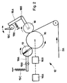
- Paper strip 2 is cut from of a coil or of a wafer 20 comprising a core 21 mounted on an axis 22.
- the strip of paper passes through a series of guide rollers 10 then guide candles 11 to be brought towards part 12 of the machine where the connection is made as will be seen below.
- the strip 2 is taken by other guide rollers to the drive roller 13 which imposes its running speed on the paper strip 2, generally of the order of 400 to 500 m / min.
- the paper strip 2 is directed towards the upper part of the machine 1 to surround the rod of cigarette filters, as indicated above.
- the axis 22 supporting the wafer 20 opposes a slight braking torque in order to keep the paper strip 2 taut between the wafer 20 and the drive roller 13.
- a new wafer 23 has previously been installed, by known means, on an axis 24 situated parallel to and behind the axis 22.
- the end of the paper strip 2A forming the upper turn of the wafer 23a has been brought manually, through the guide rollers 15, to the connection part 12.
- the free end of the paper strip 2A is fixed on the acceleration roller 16.
- the cell 14 detects that the wafer 20 is almost empty, it controls the setting in rotation of the acceleration roller 16, in order to bring the paper strip 2A, which over a portion of its path in the connection part 12 circulates parallel to the strip of paper 2 still supplied by the wafer 20, at a speed of movement substantially equal to the speed of movement of the latter.
- the diameter of the latter constantly increases, depending on the thickness of the paper strip 2A as well as on the length , respectively of the number of turns already wound up by said strip around the roller 16, which means that the speed of movement of the paper, determined by the speed of rotation of the roller 16 as well as by its diameter, cannot be determined with precision, and the moment when the two strips of paper 2 and 2A circulate at the same speed cannot be determined either.
- the running speed of the ribbon 2 is lowered during this operation to about half of its nominal speed.
- a blade not shown in the figure, carrying a piece of double-sided adhesive tape places said tape between the two strips of paper 2 and 2A, between the two rollers 17, which are then brought together to press the tapes against each other, on either side of the adhesive tape, in order to ensure the connection of the strip 2A to the strip 2.
- cutting blades not shown in the figure, cut the portion of the tape 2A located before the junction as well as that of the tape 2 located after the junction.
- the paper tape 2 which continues its path in the machine 1 is cut off as soon as this last operation is completed from the wafer 23.
- connection device In the connection device according to the invention, and as can be seen more particularly in FIG. 2, means have been added on the connection part 12 preventing the strip 2A from sliding on the external surface of the acceleration roller 16 , preferably consisting of a support roller 18, as well as a receiving roller 19.
- the end of the strip does not is no longer attached to the acceleration roller 16, but has passed over a portion of its periphery, being strongly pressed against the roller 16 by the support roller 18, preferably comprising a peripheral surface of soft material, such as rubber or a synthetic material, then is then fixed to the take-up roller 19, for example in a slot arranged diametrically therein.
- Simple mechanical means make it possible to ensure the pressure of the rollers 18 and 19 against the acceleration roller 16 as well as their drive.
- the lever 18A, pivoting about an axis 18B is controlled by the cam lever 18C to strongly press the strip 2A against the acceleration roller 16; when the cam lever 18C is released, the spring 18D acts on the lever 18A in order to move it away from the acceleration roller 16 thus allowing the end of the ribbon 2A to pass, as indicated above.
- the take-up roller 19 is pivotally attached to the end of a lever 19A, freely pivoting itself around an axis 19B, the spring 19C acting to press the take-up roller 19 against the acceleration roller 16.
- the acceleration roller 16 is driven by drive means 16A, acting through clutch means 16B, so that after a given time, the sliding of the clutch means 16B having canceled, the acceleration roller 16 rotates at a constant speed, corresponding to that of the drive means 16A, this speed preferably corresponding to the nominal drive speed of the machine, respectively to the nominal speed of movement of the ribbon 2 on the machine.
- the tape 2A does not slide on the acceleration roller 16 and its running speed is exactly that determined by the tangential speed of the acceleration roller 16 and since the diameter of the latter this remains constant, the running speed of the ribbon 2A can be exactly determined and adjusted in order to correspond to that of the ribbon 2.
- the running speed of the tape 2A can be easily stabilized, possibly by measuring the speed of rotation of the roller 16, and the two tapes 2 and 2A can be joined in the same manner as mentioned above.
- the means for inverting the wafers 20 and 23 making it possible to place the full wafer 23 behind the wafer being unwound 20 are those used on the manufacturing machines known in the art.
- the method and the connection device according to the invention which are very simple in design, it is possible to connect the two bands at a stabilized speed, reliably and without the need to decrease the operating speed of the machine.
- the productivity of the machine is greatly increased compared to those equipped with a device according to the prior art, since the only filters to be eliminated are those comprising a double layer of wrapping paper, ie those comprising the connection of the two strips of paper.
- the only filters to be eliminated are those comprising a double layer of wrapping paper, ie those comprising the connection of the two strips of paper.
Landscapes
- Manufacturing Of Cigar And Cigarette Tobacco (AREA)
Priority Applications (1)
| Application Number | Priority Date | Filing Date | Title |
|---|---|---|---|
| EP92810946A EP0601258A1 (de) | 1992-12-03 | 1992-12-03 | Verfahren und Vorrichtung zum Verbinden von Papierbahnen, insbesondere von Papierbahnen, die für das Einwickeln von einem Produkt der Tabakindustrie bestimmt sind |
Applications Claiming Priority (1)
| Application Number | Priority Date | Filing Date | Title |
|---|---|---|---|
| EP92810946A EP0601258A1 (de) | 1992-12-03 | 1992-12-03 | Verfahren und Vorrichtung zum Verbinden von Papierbahnen, insbesondere von Papierbahnen, die für das Einwickeln von einem Produkt der Tabakindustrie bestimmt sind |
Publications (1)
| Publication Number | Publication Date |
|---|---|
| EP0601258A1 true EP0601258A1 (de) | 1994-06-15 |
Family
ID=8212042
Family Applications (1)
| Application Number | Title | Priority Date | Filing Date |
|---|---|---|---|
| EP92810946A Withdrawn EP0601258A1 (de) | 1992-12-03 | 1992-12-03 | Verfahren und Vorrichtung zum Verbinden von Papierbahnen, insbesondere von Papierbahnen, die für das Einwickeln von einem Produkt der Tabakindustrie bestimmt sind |
Country Status (1)
| Country | Link |
|---|---|
| EP (1) | EP0601258A1 (de) |
Cited By (1)
| Publication number | Priority date | Publication date | Assignee | Title |
|---|---|---|---|---|
| CN115402839A (zh) * | 2022-09-05 | 2022-11-29 | 南京大树智能科技股份有限公司 | 烟机盘纸自动更换机的换盘方法 |
Citations (3)
| Publication number | Priority date | Publication date | Assignee | Title |
|---|---|---|---|---|
| FR2272933A1 (en) * | 1974-05-29 | 1975-12-26 | Bodenan Robert | Method of joining two bands of e.g. paper - uses rolls to move bands together cut, apply adhesive tape and move apart |
| DE2805384A1 (de) * | 1978-02-09 | 1979-08-23 | Hauni Werke Koerber & Co Kg | Vorrichtung zum verbinden des streifens einer ablaufenden bobine mit dem neuen streifen einer ersatzbobine |
| DE3510322A1 (de) * | 1984-04-07 | 1985-10-17 | Hauni-Werke Körber & Co KG, 2050 Hamburg | Vorrichtung zum herstellen einer verbindung zwischen einem ablaufenden streifen und einem neu bereitgestellten streifen |
-
1992
- 1992-12-03 EP EP92810946A patent/EP0601258A1/de not_active Withdrawn
Patent Citations (3)
| Publication number | Priority date | Publication date | Assignee | Title |
|---|---|---|---|---|
| FR2272933A1 (en) * | 1974-05-29 | 1975-12-26 | Bodenan Robert | Method of joining two bands of e.g. paper - uses rolls to move bands together cut, apply adhesive tape and move apart |
| DE2805384A1 (de) * | 1978-02-09 | 1979-08-23 | Hauni Werke Koerber & Co Kg | Vorrichtung zum verbinden des streifens einer ablaufenden bobine mit dem neuen streifen einer ersatzbobine |
| DE3510322A1 (de) * | 1984-04-07 | 1985-10-17 | Hauni-Werke Körber & Co KG, 2050 Hamburg | Vorrichtung zum herstellen einer verbindung zwischen einem ablaufenden streifen und einem neu bereitgestellten streifen |
Cited By (1)
| Publication number | Priority date | Publication date | Assignee | Title |
|---|---|---|---|---|
| CN115402839A (zh) * | 2022-09-05 | 2022-11-29 | 南京大树智能科技股份有限公司 | 烟机盘纸自动更换机的换盘方法 |
Similar Documents
| Publication | Publication Date | Title |
|---|---|---|
| CH691156A5 (fr) | Ligne d'alimentation d'une machine de production de filtres de cigarettes. | |
| EP0475886B1 (de) | Vorrichtung und Verfahren zum Öffnen einer Papierrolle und zum Verbinden von dem Ende einer Papierbahn an das Ende einer anderen Papierbahn | |
| EP0656853B1 (de) | Verfahren zum verpacken von ladungen mittels einer streckfolie, maschine und folie zur ausübung des verfahrens | |
| FR2499033A1 (fr) | Procede et dispositif pour regulariser le transfert de produits solides identiques | |
| FR2566754A1 (fr) | Machine pour enrouler des bandes ou des feuilles sur une ame | |
| EP0340101A1 (de) | Kassette zur Aufbewahrung und Abgabe von Fäden oder Faserband unter vorgeregelter Spannung, verwendbar in einer Maschine zur Anfertigung von Hohlkörpern durch Wickeln von Fasermaterial | |
| EP1560714B1 (de) | Vorrichtung zur zuführung eines gedruckten coupons zwecksausstattung insbesondere eines thermodruckmechanismus | |
| EP3565777B1 (de) | Verfahren und vorrichtung zum kontinuierlichen kreuzwickeln von gummierstreifen um spulen | |
| FR2528023A1 (fr) | Procede et dispositif pour la reprise de produits plats se presentant en disposition en ecailles, en particulier pour la reprise de feuilles imprimees | |
| EP0944542B1 (de) | Wickelmaschine für ein flaches endloses element zur bildung von bahnwickeln | |
| WO2002083533A1 (fr) | Procede pour recharger une fardeleuse a l'aide d'un film plastique, et fardeleuse mettant en oeuvre le procede. | |
| EP1577219B1 (de) | Vorrichtung zum Anbringen eines Tragegriffs | |
| FR2930243A1 (fr) | Dispositif de fourniture et installation de depose d'une bande de gomme. | |
| FR2876365A1 (fr) | Procede et dispositif d'enroulement en bobine d'une bande | |
| EP1747158B1 (de) | Verfahren zur herstellung einer zentralen abwickelrolle und rolle | |
| FR2625486A1 (fr) | Procede et installation de conditionnement automatique en rouleau ou en bobine des coupes d'une bande de matiere | |
| EP1940712B1 (de) | Wickelverfahren und maschine für die lagerung von flachen elementen | |
| FR2722127A1 (fr) | Procede et dispositif pour le decoupage de produits photographiques en bandes | |
| FR3018795A1 (fr) | Procede et module de decoupage d'une bande de textile non tisse dans un procede d'enroulage de ladite bande autour d'une bobine de reception entrainee en rotation | |
| EP4330006B1 (de) | Verbessertes verfahren und vorrichtung zum kontinuierlichen aufwickeln von gummistreifen zu spulen | |
| FR2497781A1 (fr) | Procede pour changer les bobines et les mandrins des machines d'enroulement sans axe | |
| EP0072315A1 (de) | Verfahren und Maschine zur Herstellung eines Rohrförmigen Zylinders aus Karton, insbesondere eines Fasskörpers, und Kartonzylinder durch dieses Verfahren hergestellt | |
| FR2754516A1 (fr) | Dispositif de conditionnement en continu de cachets en bandes d'etuis individuels | |
| EP0652173B1 (de) | Kontinuierliche Abwickelmaschine für Bahnmaterial mit einer automatischen Vorrichtung zum Schneiden und Stossverbinden | |
| FR2688770A1 (fr) | Dispositif de defilement d'une bande souple ou analogue. |
Legal Events
| Date | Code | Title | Description |
|---|---|---|---|
| PUAI | Public reference made under article 153(3) epc to a published international application that has entered the european phase |
Free format text: ORIGINAL CODE: 0009012 |
|
| AK | Designated contracting states |
Kind code of ref document: A1 Designated state(s): AT BE CH DE DK ES FR GB GR IE IT LI LU MC NL PT SE |
|
| RBV | Designated contracting states (corrected) |
Designated state(s): BE CH DE FR GB IT LI NL |
|
| 17P | Request for examination filed |
Effective date: 19941004 |
|
| 17Q | First examination report despatched |
Effective date: 19950206 |
|
| 18D | Application deemed to be withdrawn |
Effective date: 19950613 |