EP0552885A1 - Verfahren und Vorrichtung zur Feinstbearbeitung von Bremstrommeln - Google Patents
Verfahren und Vorrichtung zur Feinstbearbeitung von Bremstrommeln Download PDFInfo
- Publication number
- EP0552885A1 EP0552885A1 EP93300223A EP93300223A EP0552885A1 EP 0552885 A1 EP0552885 A1 EP 0552885A1 EP 93300223 A EP93300223 A EP 93300223A EP 93300223 A EP93300223 A EP 93300223A EP 0552885 A1 EP0552885 A1 EP 0552885A1
- Authority
- EP
- European Patent Office
- Prior art keywords
- set forth
- brake drum
- braking surface
- rotation
- shoe
- Prior art date
- Legal status (The legal status is an assumption and is not a legal conclusion. Google has not performed a legal analysis and makes no representation as to the accuracy of the status listed.)
- Withdrawn
Links
Images

Classifications
-
- B—PERFORMING OPERATIONS; TRANSPORTING
- B24—GRINDING; POLISHING
- B24B—MACHINES, DEVICES, OR PROCESSES FOR GRINDING OR POLISHING; DRESSING OR CONDITIONING OF ABRADING SURFACES; FEEDING OF GRINDING, POLISHING, OR LAPPING AGENTS
- B24B5/00—Machines or devices designed for grinding surfaces of revolution on work, including those which also grind adjacent plane surfaces; Accessories therefor
- B24B5/02—Machines or devices designed for grinding surfaces of revolution on work, including those which also grind adjacent plane surfaces; Accessories therefor involving centres or chucks for holding work
- B24B5/06—Machines or devices designed for grinding surfaces of revolution on work, including those which also grind adjacent plane surfaces; Accessories therefor involving centres or chucks for holding work for grinding cylindrical surfaces internally
- B24B5/065—Machines or devices designed for grinding surfaces of revolution on work, including those which also grind adjacent plane surfaces; Accessories therefor involving centres or chucks for holding work for grinding cylindrical surfaces internally for brake drums
-
- B—PERFORMING OPERATIONS; TRANSPORTING
- B24—GRINDING; POLISHING
- B24B—MACHINES, DEVICES, OR PROCESSES FOR GRINDING OR POLISHING; DRESSING OR CONDITIONING OF ABRADING SURFACES; FEEDING OF GRINDING, POLISHING, OR LAPPING AGENTS
- B24B35/00—Machines or devices designed for superfinishing surfaces on work, i.e. by means of abrading blocks reciprocating with high frequency
Definitions
- This invention relates to finishing brake drums and more particularly to a method and apparatus using an abrasive film to micro-finish the braking surface of a brake drum.
- brake drums as typically found on motor vehicles, have their braking surfaces finished prior to mounting onto a motor vehicle.
- finishing of brake drums has been of two varieties.
- Another method used for finishing the braking surface substitutes a honing stone for the single point tool.
- the results, however, are not a substantial improvement.
- the honing stone is drawn across the rotating braking surface.
- the lead angle of the honing stone similarly causes a helical groove to be cut into the braking surface of the brake drum.
- the helix again operates to pull an applied brake shoe axially out of the brake drum which results in mechanical shock, vibration and brake slap once the brake shoe is released.
- An additional aspect of the brake drum having a helix in the finish of its braking surface is that the surface roughness (R a ) of the finish is greater than that required for braking purposes.
- R a surface roughness
- the braking surface when viewed in cross section, is not straight and also exhibits a bore taper from the inboard portion of the braking surface, when compared against a reference axis drawn through the center rotation of the brake drum.
- the brake shoe experiences twisting or only partial application against the braking surface.
- the braking surface is straight and exhibits little or no taper.
- Eccentricity of the braking surface, relative to the center of rotation of the brake drum, is also undesirable and results in uneven finishing of the braking surface and uneven wear of the brake pad and drum lining.
- eccentricity can result from a separate mounting plate being incorporated into a casting mold and the casting of the remaining portions of the brake drum thereonto.
- the present invention seeks to eliminate the brake slap, vibration and mechanical shock which typically accompany the formation of a helix in the braking surface. By eliminating the helix, the present invention also seeks to decrease the surface roughness previously associated with brake drums.
- An additional object of this invention is to permit the micro-finishing process to affect the geometry of the braking surface.
- the present invention aims to increase the roundness of the braking surface, increase its cross sectional straightness, and to decrease the bore taper of the braking surface.
- Another object of the present invention is to decrease eccentricity existing between the braking surface and the center rotation of the brake drum itself.
- the apparatus and method of the present invention seeks to gage the micro-finishing of the braking surface from a center rotation established by the braking surface.
- Still another object of this invention is to decrease the costs associated with finishing the brake drum braking surface.
- the present invention provides a micro-finishing apparatus and method for micro-finishing the inner cylindrical braking surface of a brake drum.
- a center of rotation is gaged from the braking surface and is used to establish the actual center of rotation for the brake drum.
- eccentricity between the two is eliminated.
- the brake drum is mounted to the micro-finishing apparatus in a manner which simulates the forces experienced by the brake drum when actually mounted to a motor vehicle.
- the micro-finishing apparatus uses an arcuate tool or shoe having a surface which generally corresponds to the cylindrical braking surface of the brake drum. An abrasive film is supplied so as to be positioned over the surface of the shoe.
- abrasive film During micro-finishing, relative movement is established between the abrasive film and the braking surface with the abrasive film and the shoe being urged against the braking surface of the brake drum.
- the abrasive film can also be advanced during the actual micro-finishing process to continually provide for the use of new or clean film.
- the apparatus is also provided with an assembly for oscillating the abrasive film relative to the braking surface.
- micro-finishing process can be outlined as follows:
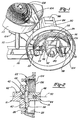
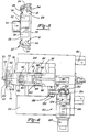
- an apparatus for micro-finishing a brake drum braking surface is generally illustrated in the figures and designated at 10.
- the apparatus 10 itself may be broken down into its several components which include but are not limited to a gaging assembly 12, a mounting assembly 14, a rotation assembly 16, a shoe assembly 18, and an oscillation assembly 20. While the above assemblies are referred to as being distinct from one another, it is important to note that various elements of these assemblies are interrelated and perform functions which relate to more than one of the assemblies.
- a common brake drum can be formed by a variety of methods. Perhaps the most common of these methods is the casting of a skirt or cylindrical portion 24 onto a preformed mounting or face plate 26. During the initial forming, the skirt 24 of the brake drum 22 is cast so as to include an interior braking surface 28. The braking surface 28 is a substantially cylindrical surface which extends continuously around the interior of the skirt 24. Unfortunately, the casting of the skirt 24 does not provide the brake drum 22 with all of its desired characteristics.
- the apparatus 10 and method of the present invention are primarily directed to this characteristic.
- Another desired characteristic, the braking surface 28 being coaxial with the center of rotation of the brake drum 22, is not ensured by casting and often occurs as a result of the skirt 24 being cast onto the face plate 26. This characteristic is also given particular attention by the apparatus 10 and method of the present invention as more fully set out below.
- a problem which often develops when the skirt 24 of the brake drum 22 is cast onto the face plate 26, is that the center of rotation defined by the braking surface 28 will differ from a center of rotation established by the face plate 26, more particularly a mounting bore 30 formed in the face plate 26.
- the finishing process itself should not alter the braking surface geometry.
- the apparatus 10 and method of the present invention eliminate these differing centers of rotation by forming a new mounting bore 32 in the face plate 26 while gaging the new mounting bore's 32 position from the braking surface 28, thereby ensuring that the center of rotation of the new mounting bore 32 corresponds with that of the braking surface 28.
- the gaging assembly 12 includes gage arms 34 which are synchronously moved outward to engage the braking surface 28 and establish an axis corresponding to the center of rotation of the braking surface 28. While only two gaging arms 34 are illustrated, it is important that three gage arms 34 are used. The three gage arms 34 are equidistantly spaced around the circumference of the braking surface 28 so as to geometrically establish a center or rotation with respect to the braking surface 28.
- the die 36 includes a cylindrical inner surface 38 having a diameter which corresponds in size that of desired mounting bore 32 which, in turn, corresponds to that portion of the vehicle axle assembly (not shown) to which the brake drum 22 is to be mounted.
- a punching tool 40 is applied to the opposing side of the face plate 26 so as to cut the new mounting bore 32 into the face plate 26.
- the new mounting bore 32 can be created by other forming methods, including, but not limited to, boring, drilling and stamping.
- the new mounting bore 32 and thus the brake drum 22 itself, will have a center or rotation which substantially corresponds to that of the braking surface 28.
- eccentricity between the center of rotation of the brake drum 22 and the center of rotation of the braking surface 28 is significantly eliminated or reduced.
- the mounting assembly 14 is best illustrated in Figures 1-4.
- the new mounting bore 32 is inserted over a pilot 42.
- the pilot 42 is mounted within a cavity in a tailstock 44 and biased outwardly therefrom by a spring 46.
- the pilot also includes a tapered engagement surface 48 which coacts with the mounting bore 32 to locate and center the brake drum 22 onto the pilot 42.
- Being biased by the spring 46 allows the pilot 42 to accommodate brake drums 22 having mounting bores 32 of differing diameters when clamped against the tailstock 44 and having the tapered engagement surface 48 allows the pilot to readily center the brake drum 22.
- the center of rotation of the brake drum 22, the braking surface 28 and the mounting bore 32 will correspond with a rotational axis 50 extending through the pilot 42 and the tailstock 44 of the micro-finishing apparatus 10.
- an actuator or hydraulic cylinder 66 (hereinafter quill cylinder 66), mounted (not shown) to a base 54 of the micro-finishing apparatus 10, is actuated to axially move a quill 68 in which the tailstock 44 is journaled for rotation.
- This action clamps the face plate 26 of the brake drum 22 with an appropriate force between the tailstock 44 and a positive stop, headstock 62, being simultaneously applied from the opposing side of the brake drum 22.
- the headstock 62 also includes a recess 64 to accommodate that portion of the pilot 42 extending through the brake drum 22.
- bearings 70 are provided within the quill 68 so as to rotationally support the tailstock 44.
- a securement assembly of a type well known within the industry is also used to prevent inadvertent withdrawal of the tailstock 44 from the quill 68.
- the quill 68 itself is supported within a frame 86 of the shoe assembly 18 which is more fully discussed below.
- the rotation assembly 16 includes a motor (not shown) which is used to rotationally drive the headstock 62, thereby inducing rotation of the brake drum 22, the tailstock 44 and the pilot 42. Once rotation of the brake drum 22 has been established, the shoe assembly 18 is actuated to begin micro-finishing of the braking surface 28.
- the shoe assembly 18 generally includes a polish shoe 74 which is pivotally mounted to a carrier arm 76 at opposing pivot points 78.
- the polish shoe 74 is pivotable about an axis which is generally perpendicular to the rotational axis 50 discussed above.
- the polish shoe 74 also has an arcuate engagement surface 80 which substantially corresponds in shape to that desired in the cylindrical braking surface 28 and therefore promotes increased roundness in the braking surface 28. Insert
- the engagement surface 80 is constructed of a rigid and hard material which will not deform or give during the micro-finishing process.
- the carrier arm 76 of the preferred embodiment has a yoke type construction.
- a stub 82 extending from one end of the carrier arm 76, provides a mount for the polish shoe 74 and a pair of pivot arms 84, extending oppositely therefrom, mount the carrier arm 76 to the frame 86 of the shoe assembly 18 at pivot points 88.
- the body 90 of the carrier arm exhibits a generally inverted wedge shape, which is best seen in Figure 3.
- body 90 Centrally in the wedge shape body 90 are a pair of slides or rollers 92.
- the pivoting or rotational movement of the carrier arm 76 is generally illustrated by arrow 94.
- the pivotable mounting at 78 of the polish shoe 74 allows for the engagement surface 80 to flatly seat against the braking surface 28, substantially across its width, in response to the pivoting or rotation of the carrier arm 76. With the polish shoe 74 lying flat against the braking surface 28, a micro-finished braking surface 28 of decreased bore taper can be produced.
- an actuator or hydraulic cylinder 96 (hereinafter polish cylinder 96) is operated to advance a ram 98 having an upright wedge shaped driver 100 mounted to the forward most end thereof.
- the wedge driver 100 is advanced and engages the rollers 92 of the carrier arm 76. Further advancement of the wedge driver 100 causes the rollers 92 to move upward along a ramped surface 102 of the wedge driver 100, thereby upwardly rotating the carrier arm 76 and raising the polish shoe 74.
- the present invention utilizes a tape or film 104 having an abrasive surface 106.
- the abrasive surface 106 of the film 104 can be formed from a variety of materials and, as such, the film 104 may be impregnated with diamonds, tungsten carbide, honing stones or other types of abrading materials.
- the film 104 is routed from a supply roll 108, conveniently positioned within a holder 110 mounted to the micro-finishing apparatus 10, over the engagement surface 80 of the polishing shoe 74.
- a feed spindle 112 rotationally supported within a mounting bracket 114, receives the film 104 from the supply roll 108 and angularly aligns it with the engagement surface 80.
- the film 104 proceeds over the engagement surface 80 and is maintained in alignment therewith by the surface roughness of honing stones 116 positioned in the engagement surface 80.
- the honing stones 116 may be aligned and a roughened surface may be given to the engagement surface 80 of the polishing shoe 74 to hold the film 104 in position.
- the film 104 passes over a take-up spindle 118, rotatably held in a mounting bracket 120, which routes the tape 104 away from the micro-finishing apparatus 10 to a discarding or waste area.
- the brake drum 22 is rotated as discussed above and the polishing shoe 74 is raised by the carrier arm 74 and wedge driver 100 to cause abrasive contact between the abrasive surface 106 of the film 104 and the braking surface 28.
- the film 104 is advanced by a feed mechanism (not shown) across the engagement surface 108 of the polish shoe 74.
- a clean or fresh abrasive surface 106 is used to micro-finish the braking surface 28.
- the shoe assembly 18, including the polishing shoe 74 and the film 104 is axially oscillated along the rotational axis 50.
- the oscillation assembly 20 mentioned above is coupled to the shoe assembly 18.
- the oscillation assembly 20 is illustrated in Figure 4.
- the primary working member of the oscillation assembly 122 is an eccentric shaft 124 of which a first end 126 is connected to an oscillating motor, generally designated at 128.
- the oscillating motor 128 can be of numerous variety, however, a hydraulic motor is preferred.
- a second end 130 of the eccentric shaft 124 is rotationally journaled in one end of a linkage 132 by bearings 134.
- the linkage is connected at its opposing end to a mounting portion 136 of the shoe assembly frame 86 by a pivotal connection 138.
- the frame 86 itself is supported and carried by oscillation slide members 140 which are mounted for axial movement along rails 142 of the main slide 55.
- the oscillatory movement of the shoe assembly 18 created by the oscillation assembly 20 thus results in axial movement of the abrasive film 104, and the polish shoe 74, relative to the braking surface 28. Relative movement between the film 104 and the polish shoe 74 is inhibited because of the roughened surface of the honing stone 116 of the shoe 74.
- the oscillatory movement is beneficial since it ensures that a straight braking surface 28 will be promoted. It is anticipated that oscillatory movement need not be of a great magnitude and that an oscillation of one eight of an inch will suffice.
Landscapes
- Engineering & Computer Science (AREA)
- Mechanical Engineering (AREA)
- Braking Arrangements (AREA)
- Grinding And Polishing Of Tertiary Curved Surfaces And Surfaces With Complex Shapes (AREA)
- Finish Polishing, Edge Sharpening, And Grinding By Specific Grinding Devices (AREA)
Applications Claiming Priority (2)
| Application Number | Priority Date | Filing Date | Title |
|---|---|---|---|
| US07/823,137 US5249393A (en) | 1992-01-21 | 1992-01-21 | Brake drum micro-finishing apparatus |
| US823137 | 1992-01-21 |
Publications (1)
| Publication Number | Publication Date |
|---|---|
| EP0552885A1 true EP0552885A1 (de) | 1993-07-28 |
Family
ID=25237896
Family Applications (1)
| Application Number | Title | Priority Date | Filing Date |
|---|---|---|---|
| EP93300223A Withdrawn EP0552885A1 (de) | 1992-01-21 | 1993-01-14 | Verfahren und Vorrichtung zur Feinstbearbeitung von Bremstrommeln |
Country Status (4)
| Country | Link |
|---|---|
| US (1) | US5249393A (de) |
| EP (1) | EP0552885A1 (de) |
| JP (1) | JPH0691511A (de) |
| CA (1) | CA2087312C (de) |
Cited By (2)
| Publication number | Priority date | Publication date | Assignee | Title |
|---|---|---|---|---|
| US6001006A (en) * | 1996-12-31 | 1999-12-14 | Societedes Procedeset Machines Speciales | Machine for machining internal surfaces of axisymmetric workpieces using an abrasive strip |
| CN111421424A (zh) * | 2020-03-10 | 2020-07-17 | 金菁 | 一种汽车制动鼓的无损拆隔板设备 |
Families Citing this family (5)
| Publication number | Priority date | Publication date | Assignee | Title |
|---|---|---|---|---|
| USD373718S (en) | 1995-03-10 | 1996-09-17 | Rondeau Donald G | Combined staging bracket and double sided clamp back rail |
| US6210256B1 (en) * | 1999-12-31 | 2001-04-03 | United Microelectronics Corp. | Continuous pad feeding method for chemical-mechanical polishing |
| US6516926B2 (en) | 2001-03-16 | 2003-02-11 | Delphi Technologies, Inc. | Piston rod surface finish requirement for MR dampening devices |
| CN111941117B (zh) * | 2020-08-28 | 2024-10-22 | 安徽合力股份有限公司 | 一种制动鼓定位夹具 |
| CN114043333B (zh) * | 2021-10-27 | 2022-09-09 | 盐城工学院 | 一种矿车制动器蹄块去毛刺装置 |
Citations (2)
| Publication number | Priority date | Publication date | Assignee | Title |
|---|---|---|---|---|
| EP0161748A2 (de) * | 1984-05-07 | 1985-11-21 | Industrial Metal Products Corporation | Einrichtung und Verfahren zur Feinstbearbeitung von Oberflächen |
| DE3918847A1 (de) * | 1989-06-09 | 1990-12-13 | Marxen Walter | Verfahren und vorrichtung zum schleifen von innenradiusflaechen |
Family Cites Families (19)
| Publication number | Priority date | Publication date | Assignee | Title |
|---|---|---|---|---|
| US2165566A (en) * | 1934-11-27 | 1939-07-11 | Edgar T Meakin | Apparatus and method for grinding and polishing bore holes |
| US2115461A (en) * | 1935-12-07 | 1938-04-26 | Messerschmitt Boelkow Blohm | Polishing machine |
| US2164811A (en) * | 1938-02-15 | 1939-07-04 | Carl W Floss | Automatic honing mechanism and control means therefor |
| US2313442A (en) * | 1939-02-23 | 1943-03-09 | Micromatic Hone Corp | Honing tool |
| SU878511A1 (ru) * | 1974-12-25 | 1981-11-07 | Ленинградский Дважды Ордена Ленина Металлический Завод Им. Ххп Съезда Кпсс | Устройство дл чистовой обработки абразивным инструментом |
| DE2604858A1 (de) * | 1976-02-07 | 1977-08-11 | Beukenberg Maschf | Verfahren und vorrichtung zur regelung des arbeitsdruckes eines zu einer schubkolbeneinheit gefoerderten hydraulischen mediums |
| US4328647A (en) * | 1980-04-09 | 1982-05-11 | Brammall, Inc. | Inside, outside honing tool |
| FR2504048A1 (fr) * | 1981-04-17 | 1982-10-22 | Citroen Sa | Rodoir a barrettes |
| US4682444A (en) * | 1984-05-07 | 1987-07-28 | Industrial Metal Products Corporation | Microfinishing apparatus and method |
| US4601133A (en) * | 1984-12-21 | 1986-07-22 | Kraftwerk Union Aktiengesellschaft | Manipulator head with grinding device for pipes or pipelines |
| US4707944A (en) * | 1986-02-18 | 1987-11-24 | Parsons Edward K | Apparatus for honing a cylinder |
| US4643055A (en) * | 1986-05-09 | 1987-02-17 | Ammco Tools, Inc. | Lathe spindle assembly |
| US4870786A (en) * | 1986-11-01 | 1989-10-03 | Bryant Grinder Corporation | Workstock |
| US4993190A (en) * | 1987-03-19 | 1991-02-19 | Canon Kabushiki Kaisha | Polishing apparatus |
| JPH0646452B2 (ja) * | 1987-09-21 | 1994-06-15 | 富士写真フイルム株式会社 | 磁気テープクリーニング装置 |
| JPH0624682B2 (ja) * | 1987-12-26 | 1994-04-06 | 株式会社日進製作所 | ラッピングフィルムを用いた超仕上げ装置 |
| US5148639A (en) * | 1988-07-29 | 1992-09-22 | Canon Kabushiki Kaisha | Surface roughening method for organic electrophotographic photosensitive member |
| JPH0683957B2 (ja) * | 1988-11-10 | 1994-10-26 | 信越半導体株式会社 | 円筒研磨装置 |
| US5109632A (en) * | 1990-04-03 | 1992-05-05 | Ppg Industries, Inc. | Automatic interlayer trimming |
-
1992
- 1992-01-21 US US07/823,137 patent/US5249393A/en not_active Expired - Fee Related
-
1993
- 1993-01-14 EP EP93300223A patent/EP0552885A1/de not_active Withdrawn
- 1993-01-14 CA CA002087312A patent/CA2087312C/en not_active Expired - Fee Related
- 1993-01-21 JP JP5008409A patent/JPH0691511A/ja active Pending
Patent Citations (2)
| Publication number | Priority date | Publication date | Assignee | Title |
|---|---|---|---|---|
| EP0161748A2 (de) * | 1984-05-07 | 1985-11-21 | Industrial Metal Products Corporation | Einrichtung und Verfahren zur Feinstbearbeitung von Oberflächen |
| DE3918847A1 (de) * | 1989-06-09 | 1990-12-13 | Marxen Walter | Verfahren und vorrichtung zum schleifen von innenradiusflaechen |
Cited By (3)
| Publication number | Priority date | Publication date | Assignee | Title |
|---|---|---|---|---|
| US6001006A (en) * | 1996-12-31 | 1999-12-14 | Societedes Procedeset Machines Speciales | Machine for machining internal surfaces of axisymmetric workpieces using an abrasive strip |
| CN111421424A (zh) * | 2020-03-10 | 2020-07-17 | 金菁 | 一种汽车制动鼓的无损拆隔板设备 |
| CN111421424B (zh) * | 2020-03-10 | 2021-05-04 | 诸暨市港灵科技有限公司 | 一种汽车制动鼓的无损拆隔板设备 |
Also Published As
| Publication number | Publication date |
|---|---|
| CA2087312C (en) | 1995-03-28 |
| CA2087312A1 (en) | 1993-07-22 |
| US5249393A (en) | 1993-10-05 |
| JPH0691511A (ja) | 1994-04-05 |
Similar Documents
| Publication | Publication Date | Title |
|---|---|---|
| CN100333876C (zh) | 磨削一种旋转对称的机器部件的方法和装置 | |
| US5863239A (en) | Microfinishing and roller burnishing machine | |
| US6767273B1 (en) | Crankpin grinding method | |
| US4798024A (en) | Method and apparatus for deburring the inner edge of part of a workpiece | |
| JP2002326153A (ja) | 円錐ころ軸受の超仕上方法及び装置 | |
| US5249393A (en) | Brake drum micro-finishing apparatus | |
| JP3984804B2 (ja) | 棒状工作物のセンタレス研削方法およびセンタレス研削装置 | |
| US6030277A (en) | High infeed rate method for grinding ceramic workpieces with silicon carbide grinding wheels | |
| US4082014A (en) | Wheelhead | |
| CN206047918U (zh) | 一种砂轮装夹机构及使用该装夹机构的砂轮修整装置 | |
| US5865667A (en) | Grinding machine | |
| JP3149906B2 (ja) | 鉄道車両用車輪の軸孔仕上げ加工方法 | |
| US5501630A (en) | Method for grinding needle points on surgical grade needle blanks | |
| EP0241468A1 (de) | Mit einem abrichtwerkzeug ausgerüsteter schleifmaschinenspindelstock. | |
| EP0656243A1 (de) | Verfahren und Vorrichtung zum Schleifen von Nadeln | |
| US3641713A (en) | Grinding machine | |
| JP4438432B2 (ja) | ラッピング加工方法 | |
| US3811234A (en) | Method of forming workpieces by abrading | |
| JP2676054B2 (ja) | 心なし研削盤におけるエンジンバルブ研削用砥石車の修整方法及びその装置 | |
| US4404772A (en) | Cylindrical grinding machine | |
| CN211915311U (zh) | 一种钢筋弯曲机 | |
| JP2000176834A (ja) | 研削砥石の修正方法、並びに修正装置及びこれを備えた研削盤 | |
| JP2001259973A (ja) | 円筒状工作物の外周面研削方法および研削装置 | |
| JPH05503883A (ja) | 孔を内面研削するための方法及び研削機 | |
| JPS6327965Y2 (de) |
Legal Events
| Date | Code | Title | Description |
|---|---|---|---|
| PUAI | Public reference made under article 153(3) epc to a published international application that has entered the european phase |
Free format text: ORIGINAL CODE: 0009012 |
|
| AK | Designated contracting states |
Kind code of ref document: A1 Designated state(s): DE ES GB IT |
|
| 17P | Request for examination filed |
Effective date: 19930910 |
|
| 17Q | First examination report despatched |
Effective date: 19950116 |
|
| 18D | Application deemed to be withdrawn |
Effective date: 19950527 |