EP0553712A1 - Dispositif de traitement par laser notamment pour l'usage médical ou dentaire - Google Patents
Dispositif de traitement par laser notamment pour l'usage médical ou dentaire Download PDFInfo
- Publication number
- EP0553712A1 EP0553712A1 EP93100869A EP93100869A EP0553712A1 EP 0553712 A1 EP0553712 A1 EP 0553712A1 EP 93100869 A EP93100869 A EP 93100869A EP 93100869 A EP93100869 A EP 93100869A EP 0553712 A1 EP0553712 A1 EP 0553712A1
- Authority
- EP
- European Patent Office
- Prior art keywords
- coupling
- laser treatment
- laser
- plug
- supply device
- Prior art date
- Legal status (The legal status is an assumption and is not a legal conclusion. Google has not performed a legal analysis and makes no representation as to the accuracy of the status listed.)
- Withdrawn
Links
- 238000013532 laser treatment Methods 0.000 title claims abstract description 67
- 230000008878 coupling Effects 0.000 claims abstract description 127
- 238000010168 coupling process Methods 0.000 claims abstract description 127
- 238000005859 coupling reaction Methods 0.000 claims abstract description 127
- XLYOFNOQVPJJNP-UHFFFAOYSA-N water Substances O XLYOFNOQVPJJNP-UHFFFAOYSA-N 0.000 claims description 13
- 239000007788 liquid Substances 0.000 claims description 6
- 239000003365 glass fiber Substances 0.000 claims description 3
- 238000011282 treatment Methods 0.000 description 24
- 230000033001 locomotion Effects 0.000 description 11
- 239000013307 optical fiber Substances 0.000 description 9
- 210000002414 leg Anatomy 0.000 description 8
- 238000007789 sealing Methods 0.000 description 7
- 238000010276 construction Methods 0.000 description 5
- 238000004519 manufacturing process Methods 0.000 description 4
- 230000003287 optical effect Effects 0.000 description 4
- 238000003860 storage Methods 0.000 description 4
- 230000008901 benefit Effects 0.000 description 3
- 239000013305 flexible fiber Substances 0.000 description 3
- 239000000203 mixture Substances 0.000 description 3
- 210000003414 extremity Anatomy 0.000 description 2
- 239000000835 fiber Substances 0.000 description 2
- 230000005484 gravity Effects 0.000 description 2
- 210000003127 knee Anatomy 0.000 description 2
- 230000001681 protective effect Effects 0.000 description 2
- 238000000926 separation method Methods 0.000 description 2
- 239000007921 spray Substances 0.000 description 2
- 238000003287 bathing Methods 0.000 description 1
- 238000005452 bending Methods 0.000 description 1
- 230000005540 biological transmission Effects 0.000 description 1
- 239000004020 conductor Substances 0.000 description 1
- 230000006735 deficit Effects 0.000 description 1
- 238000005553 drilling Methods 0.000 description 1
- 239000013013 elastic material Substances 0.000 description 1
- 239000011521 glass Substances 0.000 description 1
- 230000001771 impaired effect Effects 0.000 description 1
- 238000003780 insertion Methods 0.000 description 1
- 230000037431 insertion Effects 0.000 description 1
- 238000009434 installation Methods 0.000 description 1
- 238000012423 maintenance Methods 0.000 description 1
- 239000002245 particle Substances 0.000 description 1
- 230000002093 peripheral effect Effects 0.000 description 1
- 238000003825 pressing Methods 0.000 description 1
Images



Classifications
-
- A—HUMAN NECESSITIES
- A61—MEDICAL OR VETERINARY SCIENCE; HYGIENE
- A61C—DENTISTRY; APPARATUS OR METHODS FOR ORAL OR DENTAL HYGIENE
- A61C1/00—Dental machines for boring or cutting ; General features of dental machines or apparatus, e.g. hand-piece design
- A61C1/0046—Dental lasers
-
- A—HUMAN NECESSITIES
- A61—MEDICAL OR VETERINARY SCIENCE; HYGIENE
- A61C—DENTISTRY; APPARATUS OR METHODS FOR ORAL OR DENTAL HYGIENE
- A61C1/00—Dental machines for boring or cutting ; General features of dental machines or apparatus, e.g. hand-piece design
- A61C1/08—Machine parts specially adapted for dentistry
- A61C1/18—Flexible shafts; Clutches or the like; Bearings or lubricating arrangements; Drives or transmissions
Definitions
- a medical or dental laser treatment device There are two essential requirements for a medical or dental laser treatment device.
- a high laser beam power is desired in order to be able to carry out the treatment efficiently, and on the other hand, a handling-friendly and easy guidance of the treatment instrument is desired.
- the latter is particularly important because the practitioner during e.g. dental treatment with a laser beam does not feel any treatment resistance, as is the case with mechanically effective treatment instruments, for example a drill that is pressed against the surface to be processed with a certain pressure force during the drilling.
- Laser treatment devices are known which are set up to supply treatment instruments which contain the laser beam generating device, so that the handpieces are supplied with the energy required for laser beam generation from the control device associated with the laser treatment device.
- Laser treatment instruments of this type are of complex construction, as well as of great construction and weight.
- a laser beam generating device must be assigned to each associated laser treatment instrument, which leads to high manufacturing costs.
- a laser treatment device has been proposed in which the laser beam generating device is integrated in the control device. With such a construction, it is necessary to guide the laser beam from the control unit to the laser treatment instrument.
- a flexible fiber optic cable can be used for this. Standard screw connections are used to connect such a supply device to the control unit.
- the laser handpiece is connected to the foremost link of the articulated link arm by means of a connection piece which has a connection thread on both sides and can thus be screwed to both the laser handpiece and the arm link.
- a lens for the laser beam is arranged in the connector in this proposal.
- a medium line is provided in an arrangement bridging the connector. For this is located In the rear end area of the laser handpiece, a connecting tube protruding from its outer surface for a small medium hose that bridges the connecting piece. The medium line runs inside the laser handpiece to a nozzle arranged in the vicinity of a lateral outlet opening for the laser beam.
- the invention has for its object to design a laser treatment device of the type mentioned in such a way that a handling-friendly connection of the laser treatment instrument to the supply device and / or the supply device on the control device is possible while ensuring a simple construction and efficient media guidance.
- a plug-in / rotation coupling is provided between the control device and the supply device and / or between the supply device and the treatment instrument, which not only allows the supply device on the control device to be easily rotated and / or the laser treatment instrument to be easily rotated enables the supply device, but also forms a user-friendly quick coupling or plug connection so that the supply device and / or the laser treatment instrument can be coupled and uncoupled easily and quickly, for example in order to disinfect, maintain or replace the supply device and / or the laser treatment instrument with another type of function.
- the media lines are through the plug / turn coupling passed through and they are automatically connected or disconnected when coupling and uncoupling.
- the laser handpiece can also be turned slightly because the connecting piece and the medium line section located behind the plug-in / rotary coupling are not moved. This also applies to the foremost arm link of an articulated link arm if the laser treatment instrument according to the invention should be connected to such an articulated link arm.
- Such supply devices can be an articulated link arm through which a laser beam can be guided by means of an optical guidance system, or it can also be flexible supply hoses in the form of light guides. It is possible to use such tubular light guides in which the laser beam is guided through a glass fiber guide or through a conductor channel containing a liquid, or it is also possible to use such a tubular light guide in which the laser beam is passed through a guide channel, the inner wall of which is mirrored .
- the subclaims contain features that contribute to solving the problem, ensure precise laser beam guidance, in particular in the area of the plug-in / rotary couplings a coaxial laser beam guidance, lead to a small, simple, light and inexpensive to manufacture and expedient construction and also facilitate or improve assembly or disassembly and handling during treatment.
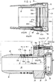
- the handpiece 2 is formed in two parts in the present embodiment with a rear sleeve part 11 and a front sleeve part or head part 12 and plugged together at the separation point 13.
- the head part 12 is firmly inserted with a pin into the sleeve part 11, so that it cannot be detached for normal handling.
- the separation point 13 is preferably provided for reasons of simple manufacture and assembly.
- the sleeve part 11 is extended by a sleeve end piece 14 of somewhat larger cross section, which overlaps an outer shoulder on the rear sleeve edge, and in which a bearing sleeve 15 is firmly inserted, the front end of which protrudes into the rear end region of the sleeve part 11 .
- the cylindrical inner wall of the bearing sleeve 15 forms a plug hole 17 into which a coaxial, hollow cylindrical plug pin 18 of the connecting piece 4 can be inserted with little movement play and can be elastically locked in the inserted position.
- a radially effective, split spring ring 19 is used, which is seated in a circumferential groove 21 arranged in the rear region of the plug pin 18 with play and is dimensioned so large that its outer jacket slightly extends beyond the outer surface area 22 of the plug pin 18.
- the spring ring 19 is compressed. In the plug end position, it snaps elastically into a corresponding inner circumferential groove 23 in the rear region of the bearing sleeve 15.
- the spring ring 19 is overpressed, which is made possible or facilitated by bevels on the spring ring 19 and / or on the inner wall 16.
- the plug pin 18 projects coaxially forward from a flange 24 which has a radial projection 25.
- a coaxial bearing ring 26 protrudes from the rear of the flange 24, which has an external thread 27 on its outer surface and an internal thread 28 in the area of the rear half of its inner surface.
- the front half of the inner lateral surface forms a cylindrical fitting hole 29, into which an optical lens 31 is inserted, which is best seen in FIG. 4 (detail X).
- a preferably flat shoulder 32 is used between the fitting hole 29 and the cylindrical through hole 33, which is somewhat smaller in cross section, in the connecting piece 4, which extends through the flange 24 and the plug pin 18.
- rotary handle elements for example small diametrically opposite holes provided ring nut 34, with which the lens 31 is pressed against the shoulder 32 by means of an intermediate ring 35 made of elastic material such as rubber.
- the connector 4 is screwed with its external thread 27 into a threaded hole 36 of the sleeve-shaped arm member 5, which rotates about its longitudinal axis 37, which coincides with the longitudinal axis 37a of the handpiece 2, on a rear, extending transversely, preferably at right angles, to the foremost arm member 5 , also sleeve-shaped arm member 38 is mounted.
- the joint arm not shown in total, has a plurality of arm members in such a number and arrangement that the mobility of the laser treatment instrument required for treatment is ensured.
- the laser beam is generated in a laser beam generating device, not shown, on which the rear end of the articulated arm is held.
- the laser beam is guided through the sleeve-shaped arm limbs.
- the laser beam is deflected by a mirror or a prism 41 deflection device so that it emerges coaxially from the arm member 5 and extends in the longitudinal axis direction 37a through the lens 31, the through hole 33 of the connector 4 and the handpiece 2.
- the cavity of the sleeve-shaped handpiece 2 or a cylindrical channel 42 which is axial in the head part 12 ends in the axial direction at the front end of the head part 12 and then preferably extends outward at a right angle.
- a laser beam deflection device preferably a mirror or a prism 43, is positioned in the region of this bend, which refracts the laser beam, which is preferably focused by the lens 31 in the prism 43, in such a way that it crosses the exit 3 and focuses on the treatment site indicated by A. , which is located in the area of the intersection of the axes of the outlet 3 and the media nozzle 9.
- the deflection device in an adjustable manner in order to be able to compensate for differences in tolerance of the laser treatment instrument 1.
- the prism 43 according to FIG. 5, which shows the detail Y, is preferably arranged or mounted in an insert 49 which, in the sense of a cartridge, can be inserted into the transverse channel 45 forming the outlet 3 or into the end region of the channel 42.
- the fitting or insert 49 is pressed or tensioned against a preferably flat fitting surface 46, which preferably extends parallel to the longitudinal axis 37a and forms the base of the transverse channel 45.
- a ring nut 47 which is screwed into the transverse channel 45 and preferably presses against the insert 49 by means of an elastic ring.
- a protective disk 48 that is transparent to the laser beam is arranged after it, which is held interchangeably in the area of the outlet 3 and thus from time to time a new one can be replaced if, for example, it has gone blind.
- the protective pane 48 can be made of glass or plastic. It is preferably fastened in a retaining ring 44 with an external thread, which can be screwed into the transverse channel 45 or into the ring nut 47, for which purpose corresponding threads are to be provided.
- the retaining ring 44 preferably has a front flange 51, in which rotary grip elements, preferably formed by external grooves, are provided for screwing in and unscrewing.
- the screw-in depth of the ring nut 47 or the retaining ring 44 is preferably limited by a stop shoulder, so that the insert 49 cannot be overloaded by the pressing force, but is maximally biased into its fitting position by the elasticity of the above-described elastic ring.
- two media hoses 52a, 52b are provided, which extend along the articulated arm and are held on the outside thereof, for example.
- the media hoses 52a, 52b are each connected to the connector 4 by means of a connection tube 53a, 53b projecting from the rear, which is firmly inserted in an axially parallel hole 54a, 54b in the extension 25.
- a channel 55a, 55b runs radially inward from the hole to an axial channel 56a, 56b, which extends forward into the area in front of the spring ring 19 and with a channel section 57a, 57b running radially outward on the outer lateral surface 22 of the plug pin 18 flows out.
- the two circumferentially offset channel sections 57a, 57b of the two media lines 7 are arranged at an axial distance a from one another.
- a circumferential groove 58a, 58b is assigned opposite each channel section 57a, 57b or its mouth opening in the inner wall 16 of the bearing sleeve 15.
- sealing rings 59a, 59b, 59c are provided, two of which are located axially in front of and behind the associated channel section 57a, 57b or the associated circumferential groove 58a, 58b.
- the sealing rings which are preferably formed by O-rings, are each located in a circumferential groove, which is preferably is arranged in the outer circumferential surface 22 of the plug pin 18.
- a radial channel section 61a, 61b leads away from the circumferential grooves 58a, 58b, which corresponds in each case to an associated radial section 62a, 62b in an insert piece 63 which is seated in an associated recess 64 or in an associated hole in the bearing sleeve 15.
- Each radial channel section 62a, 62b is connected to an axial channel section 65a, 65b in the insert 63, which opens out on the front side thereof.
- the axial channel sections 65a, 65b are also arranged offset in the circumferential direction.
- the parting lines between the associated radial channel sections 61a, 61b and 62a, 62b are each sealed by a sealing ring 66a, 66b, which is arranged in a groove in the preferably flat base surface of the recess 64 or in the inner surface of the insert 63 facing it.
- a tube 67a, 67b is firmly and tightly inserted into the front opening of each axial channel section 65a, 65b.
- the tubes lead the associated medium (compressed air, water) to the media nozzle 9.
- the front ends of the tubes 67a, 67b are firmly and tightly inserted into the rear openings of axial channels 68a, 68b, which extend to a nozzle bore 69 receiving the media nozzle 9, the central axis of which is inclined, preferably below one An angle of 45 ° to the longitudinal axis 37a is arranged.
- the media nozzle 9 has a sleeve-shaped outer nozzle part 71 and a sleeve-shaped inner nozzle part 72 accommodated in the last, which can be screwed into the nozzle bore 69 as a structural unit with an external thread arranged on the outer nozzle part 71.
- the water is supplied coaxially to the inner nozzle part 72 sealed by means of a sealing ring, the sleeve tip of which ends at a short distance in front of the common nozzle opening 73 of the outer nozzle part 71.
- the compressed air is supplied to the nozzle opening 73 through an axial channel running between the outer nozzle part 71 and the inner nozzle part 72. In the free space or gap in front of the nozzle opening 73, the compressed air and the water are automatically mixed to form a mixture or spray emerging from the nozzle opening 73.
- the above-described sealed course of the media lines 7 across the parting line between the plug pin 18 forming a coupling pin and the plug hole 17 forming a coupling bush enables the handpiece 2 to be rotated in the plug-in / rotating coupling 6 by 360 ° and more without impairment fear is.
- the above-described plug-in / rotary coupling 6 also enables a large cross section of the through hole 33, which benefits the laser beam feedthrough and line.
- the throttle valve 74 is arranged in the extension 25. In this area it is easily accessible from the outside with an adjustment tool.
- the throttle valve 74 can be arranged in an axial or radial channel which opens into the associated channel section of the media line 7, so that it can preferably change the associated media channel cross section of valve bodies which can be screwed in and out.
- the throttle valve 74 preferably has a screw 74a, which is sealed by a sealing ring on its circumference and screwed into a radial or axial bore 75, the free end of which is preferably pointed and the head end of which has a tool engagement element for turning.
- the bore 75 is preferably arranged parallel to the longitudinal axis 37a and outside the circumference of the handpiece 2 and a forward extension of the Waser channel 54a so that the screw 74a is accessible from the front.
- the screw tip can interact with the channel in the associated tube 53a.
- the laser treatment device 101 shown in FIG. 6 consists of a stand 102 with a stand foot 103, an approximately horizontal support arm 104, which is freely rotatable about a vertical axis of rotation 105 on the stand 102, a control device 106, which is located at the free end of the support arm 104 is freely pivotable about a vertical swivel axis 107, an articulated link arm 108 which is freely rotatably rotatable about a horizontal axis of rotation 109a in a pivot bearing 109 of control unit 106 and a support part 112 held on control unit 106 for holding the free end region of articulated link arm 108 in its non-use position.
- the stand base 103 is formed by a cube-shaped or cuboid box 113, on the front and / or front top area of which electrical control elements are arranged.
- This can be a main switch 114, an on / off switch, preferably lockable by a lock 115 and a safety switch 116 act, the latter two preferably being key switches.
- a large part of the existing control device is preferably arranged in the stand foot 103 forming a base part. This can be a water reservoir, a pump for water supply, a laser power supply and a microprocessor.
- the stand 102 preferably consists of a preferably telescopic support column 118 fastened in or on the box 113, consisting of a lower column part 118a, in which an upper column part 118b is vertically displaceable and can be locked in the respective sliding position.
- the support arm 104 is preferably a so-called knee lever arm with two arm parts 104a, 104b which are connected to one another at their ends facing one another in a knee lever joint so as to be pivotable about a vertical pivot axis 119.
- the rotary bearing 109 is located on one side of the cuboid housing 121 of the control device 106, so that the axis of rotation 109a extends parallel to the front of the laser treatment device 101.
- the pivot bearing 109 is arranged on the right and the support part 112 is located in the left end region of the control device 106 is.
- the articulated link arm 108 consists of at least three arm links which are rotatably or pivotably mounted about mutually perpendicular axes of rotation or pivoting.
- the articulated link arm 108 consists of six arm links, of which the first arm link 108a forms the arm-side bearing part of the rotary bearing 109.
- the further arm links 108b, 108c, 108d, 108e and 108f are each freely rotatably supported at the free end of the respective previous arm link about an axis of rotation 109b, 109c, 109d, 109e, 109f which is perpendicular to the previous axis of rotation.
- a mechanical connection in particular a screw connection, preferably with an internal thread, by means of which a laser treatment instrument 122 can be detachably attached to the link arm 108, which can correspond to that shown in FIGS. 1 to 5.
- the longitudinal central axis 123 of the laser treatment instrument 122 extends perpendicular to the axis of rotation 109. This gives it an advantageous arrangement for use in the mouth of a patient.
- the control device 106 there is a laser beam generating device, not shown in detail, which coaxially coaxially through the rotary bearing 109, i.e. the laser beam illustrated by an arrow 124 in FIG. coaxial to the axis of rotation 109a, into the articulated link arm 108.
- the pivot bearing 109 is hollow for this purpose.
- the arm members 108a to 108f are also hollow for the passage of the laser beam 124, a light guide system being integrated in the through channel of the hollow joint member arm 108, with which the laser beam 124 is guided to the free end of the joint member arm 108 and is introduced coaxially into the laser treatment instrument 122 can.
- the optical guidance system has mirrors 125 or prisms, which are indicated in the joints between the arm links 108a to 108f, and which cause the laser beam 124 to be deflected or refracted by 90 ° in the longitudinal direction of the articulated link arm 108.
- the mirror 125 or the prism is in each case attached to the previous arm link, breaking the laser beam 124 in the longitudinal direction of the subsequent arm link.
- the articulated link arm 108 is detachably connected to the control unit 106 by a plug-in coupling 131 designed as a quick coupling.
- the plug-in coupling 131 comprises a cylindrical coupling pin and a cylindrical coupling bush which receives it with little movement play.
- the coupling pin 132 is provided in one piece on the rearmost arm member 108f or as an add-on part thereon (FIG.
- the coupling pin 132 it being possible for the coupling pin 132 to be screwable to the last arm member 108f in the case of a non-one-piece design, for which purpose an external thread 133 on a coaxial sleeve projection 134 is used with which the coupling pin 132 can be screwed into an internal thread (not shown) of the arm member 108f.
- the pin portion 132a of the coupling pin 132 extends coaxially rearward from a flange 135, from the other side of which the sleeve projection 134 extends forward.
- the coupling pin 132 is penetrated by a cylindrical through hole 136, so that the pin portion 132a is sleeve-shaped.
- the front outer edge of the coupling pin 132 is rounded in order to facilitate its insertion into the coupling bush 137.
- the plug-in coupling 131 can be elastically locked in the closed position of its coupling parts and can be released by overpressing the locking when the movable coupling part moves axially.
- a radially effective, split spring washer 139 is used, which is located in the rear area of the Spigot section 132a of the spigot 132 arranged circumferential groove 141 sits with play and is dimensioned so large that its outer surface area projects beyond the outer surface area 142 of the spigot 132.
- the coupling bush 137 forms the pivot bearing part of the pivot bearing 109 assigned to the articulated link arm 108.
- the pivot bearing part assigned to the control device 106 can be mounted, for example, on the side housing wall 121a of the housing 121.
- a round hole 145 is provided in the side housing wall 121a, into which a cylindrical ring projection 146 coaxially protruding from the coupling sleeve 137 with little movement clearance surrounds with little movement play.
- a bearing disc 147 is used, which rests on the flat end face of the ring extension 146, and thus e.g. is fastened by screws and projects beyond the outside edge of the hole 145.
- the coupling sleeve 137 is thus securely mounted in the hole 145 and can be freely rotated.
- further media lines for supplying media are provided, which extend through the pivot bearing 109 and the plug coupling 131 and along the articulated link arm 108 and are connected to the laser treatment instrument 122 in the front end region thereof can.
- Such other media can be water, air, water-air mixture, electrical current and / or a so-called pilot jet.
- Two media feeds, in particular for air and water or water-air mixture, in each of one of two media lines 148, are described below by way of example.
- media lines for treatment air and / or liquid are required , such as water or spray in particular, a sealed feed, in particular in the area of the plug coupling 131 and the Detachable connection between the foremost arm member 108f and the treatment instrument 122, which is preferably also formed by a quick or plug coupling.
- These media lines 148 extend from the pump arranged in the stand base 103 or from a pump arranged in the control unit 106 to the coupling socket 137, which can be flexible media hoses 149 which can be connected to line connections 151 on the coupling socket 137, for example by plugging them on.
- the line connections 151 are located on the outer lateral surface 152 of the coupling socket 137, and one media channel 153a, 153b leads radially inward to an associated annular groove 154a, 154b in the inner lateral surface 156 of the coupling socket 137, which are axially spaced a from one another .
- a short radial channel section 157a, 157b is provided in the coupling pin 132, which passes through the outer circumferential surface 142 of the coupling section 132a in the radial plane of the associated annular groove 154a, 154b and is thus connected to it.
- Channel sections 159a, 159b extend outward from the channel sections 157a, 157b within the wall of the coupling pin 132, parallel to the longitudinal center axis of the coupling pin 132.
- the axial channel sections 159a, 159b are adjoined in the flange 135 by radially outwardly extending channel sections 161a, 161b, only one of which is visible, and from which axially parallel channel sections 162a, 162b extend, which extend outwards and at the front of the flange 135 exit.
- the above-described channel sections are formed by bores, the channel sections 159a, 159b being drilled from an inner shoulder of the through hole 136 of the coupling pin 132 and the channel sections 161a, 161b from the peripheral surface of the flange 135 and being closed at the end by plugs.
- connection sleeves 163 which are located at a distance of a few millimeters next to the associated arm member 108f.
- Two flexible media hoses 160 are plugged onto the two existing connection sleeves 163, which extend along the articulated arm 108 to its front end for the purpose of supplying the laser treatment instrument 122 and are held on the articulated arm 108, for example by bathing.
- the laser handpiece is detachably connected to the foremost arm member 108f by a plug-in / rotary coupling 164 which is comparable with the plug-in / rotary coupling described above.
- a coupling pin projecting forward is preferably provided, which can be inserted into a coupling socket of the laser handpiece and is screwed with its rear end to the foremost arm member 108f.
- Coupling pin shown is arranged and formed in mirror image of the coupling pin 132, so that the screw connection and the passage of the media lines 148 through the existing flange and the coupling can be designed according to the design of the plug coupling 131, the media in the laser handpiece to the treatment tool assigned outlet openings are guided.
- annular grooves 165 can be arranged on both sides of the annular grooves 154a, 154b or the radial channel sections 157a, 157b in the coupling sleeve 137 or in the coupling pin 132, into the sealing rings, preferably O-rings 166 are.
- An articulated link arm 108 described so far is subject to a downward torque due to its own weight, which the practitioner has to counteract during the treatment by manually holding the laser treatment instrument 122.
- a compensation device 171 is assigned to the articulated link arm 108, which at least partially compensates for its own weight in its initial position placed on the support part 112 or in a central position of its range of motion, i.e. counteracts the dead weight, so that the articulated link arm 108 is at least partially relieved of weight.
- the articulated link arm 108 is preferably arranged in such a way that its rearmost arm link 108a or its leg 172, which radially points away with respect to the axis of rotation 109a, in its initial position slopes obliquely forward (FIG. 7) or obliquely rearward (FIGS. 11 and 12) and thereby preferably extends downward.
- the compensation device 171 is designed and arranged in such a way that it generates a torque counteracting the dead weight at the rearmost arm member 108a.
- a compensation device 171a, 171b which generates the desired compensation force by means of a spring.
- the spring engages at a radial distance from the axis of rotation 109a on the rearmost arm member 108a, preferably on the coupling bush 137.
- a tension spring 173 is provided which is supported on the housing 121 and which engages the coupling bush 137 directly or by means of a pull cable 174.
- the pull rope 174 is above this certain range of rotation angle wound on the circumference of the coupling sleeve 137, preferably on the circumferential surface 175 of a flange 176 which forms the pivot bearing part in the present embodiment.
- the pull cable 174 is attached to the coupling axis 137 at its pull end, for example by means of a screw 174a.
- the maximum rotational movement generated by the compensating spring 173 can be limited by a stop or pin 174b which is fastened to the coupling bush 137 and which interacts with a stop 174c fixed to the housing.
- the design according to 7 shows the tension spring 173 in the horizontal longitudinal direction of the housing 121 which extends parallel to the front, preferably in the rear area thereof, the tension cable 174 being deflected around a deflection roller 177 which is rotatably mounted on the housing 121.
- a rotary driving connection 170 is provided between the coupling bush 137 and the plug pin 132, by means of which the compensating torque generated by the spring 173 can be transmitted to the articulated link arm 108.
- the rotary drive connection 170 is formed by a plurality of rotary drive pins 170a arranged on a coaxial pitch circle, which engage in rotary drive holes 170b and thus likewise form a plug-in coupling which is automatically closed and opened when the plug-in bolt 132 is inserted and removed.
- the rotary driving pins 170a are preferably fixedly inserted in axially parallel holes in the flange 135 and protrude rearward axially parallel therefrom in order to be able to fit into the associated rotary driving holes 170b in the coupling sleeve 137.
- a rotary driving pin 170a is sufficient for a rotary driving connection 170.
- Preferably several, e.g. four or six rotary drive pins 170a and associated rotary drive holes 170b are arranged at equal angular intervals from one another. As a result, several coupling positions are created, which are arranged offset to one another in the circumferential direction.
- the compensating spring is a torsion spring, in particular a helical or helical spring 173a, which is arranged coaxially with the axis of rotation 109a and, with its end facing the coupling bush, non-rotatably with the coupling bush 137 and at its end facing away from it with a fixed housing Support part 183 is connected.
- axially parallel angled ends of the helical spring can be used, which engage in axially parallel holes in the coupling bush 137 and the support part 183.
- the free inner cross section of the helical spring 173a is dimensioned so large that the free passage of the laser beam 124 is not hindered.
- the compensating device 171 is thus integrated into the control device 106 or its housing 121.
- the balancing force of the balancing device 171 can also be generated by a balancing weight.
- a balancing weight Such an embodiment is provided according to FIGS. 11 and 12, in which the compensating device 171 is arranged outside the control unit 106.
- a counterweight 184 is provided, which is arranged detachably or non-releasably on the rear arm member 108a or preferably 108b.
- the effective distance 185 of the balancing weight 184 is optionally adjustable.
- a particularly radial support rod 186 can be used for this purpose, on which the balance weight 184 is plugged with a hole and can be fixed, for example, by a clamping screw 187.
- FIG. 12 shows a holder 191 for the counterweight 184, which on the one hand enables the counterweight 184 to be adjusted and on the other hand detachably attaches to the leg 172.
- This holder 191 consists of a fastening clamp 192, the clamp halves 192a, 192b of which can be clamped in a position encompassing the leg 172 by fastening bolts which pass through them in holes.
- a fastening clamp has a vertical hole 194, preferably in the form of a bore, into which a support rod 186 bent with an obtuse angle can be inserted with its vertical rod section 186a and in its optionally inserted height position can be clamped by a clamping screw 195 which from the outside into a hole in the hole 194 opening threaded bore 196 can be screwed.
- the support rod section 186b which extends obliquely upwards in the installation position, serves to hold the balance weight 184.
- the balance weight 184 is by adjusting it on the support rod 186a, by adjusting the fastening clamp 192 along the leg 172 and by rotating the support rod 186 in Hole 194 adjustable.
- the counterweight 184 is arranged such that it is rotated when the arm member 108c, which is approximately in the horizontal position of use, is pivoted in and out, because the arm member 108b is also rotated about its longitudinal axis 109b. In the horizontally pivoted position of the arm member 108c, the counterweight is in its rear position, in which it exerts a large counterbalancing torque and counteracts the increased torque of the articulated arm 108. When the arm member 108c is pivoted toward the control device 106, the counterweight 184 is pivoted to the side, whereby its effective distance 185 is reduced.
- the effectiveness of the balance weight 184 is automatically adjusted as a function of the position of the arm link 108c and the torque of the articulated link arm 108 which changes as a result of this adjustment.
- the torque of the articulated arm 108 is low, and the torque of the balance weight 184 is also low because it is pivoted laterally and towards the axis of rotation 109a.
- the arrangement is further such that in the use position of the articulated arm 108 or in the middle position of the associated adjustment range of the articulated arm 108, the longitudinal central axis 188 of the support rod 186 intersects the center of gravity S of the articulated arm 108.
- the balance weight 184 is on the side to which the leg 172 extends obliquely. If the latter slants downward and preferably extending rearward, the support rod 186 extends obliquely upward to the rear.
- a driving device 170 between the coupling bush 137 and the plug or coupling pin 132 may be absent and the coupling bush 137 may be rigidly fastened.
- the coupling pin 132 is released from rotary movements when the articulated link arm 108 is pivoted about the axis 109a (wear protection).
- Such a joint 198 can be integrated in the releasable connection between the coupling pin 132 and the arm member 108a carrying it.
- the support member 112 is preferably formed with a horizontal storage surface 112a on which the free end region of the articulated link arm 108 can be positioned so that the treatment instrument 122 can also lie on the storage surface 102a and can thus rest in a horizontal arrangement.
- the support member 112 is therefore preferably plate-shaped. It is furthermore advantageous to assign a switch to the support part 112, which ensures that the device is only ready to emit the laser beam 124 to the treatment instrument 122 when the articulated link arm 108 is lifted from the support part 112.
- a microswitch can be a pressure switch or a movement switch.
- the support member 112 is slightly vertically movable or pivoted so that a movement switch an automatic, e.g. can determine resilient upward movement of the support member 112 when removing the link arm 108.
- the optical fiber cable 110 can continue axially on the coupling pin 132a or it can be angled through an angular section, as shown in FIG. 13.
- a lateral arrangement of the plug-in / rotary coupling 131a on the device side has the advantage, as in the previously described exemplary embodiments, that during the movements of the optical fiber cable 110 required for the treatment, the cable-side coupling pin 132a can rotate about its longitudinal axis 109a and thus less on bending is claimed.
- the plug-in / rotary coupling on the underside of the control device 6, preferably in the lateral and / or front end region of the existing housing.
- the optical fiber cable 110a first extends downward and then in an arc shape, an angular section not being required for the optical fiber cable 110a.
- FIG. 13 Such an embodiment is indicated in FIG. 13.
- the fiber optic cables described above can be of various configurations. There are optical fiber cables that have an optical fiber channel filled with a liquid. It can also be an optical fiber cable with an optical fiber channel, the inner surface of which is mirrored. It is also possible to use a flexible fiber optic cable.
- the end coupling elements are preferably the same at least at one end, preferably at both ends, so that an articulated link arm and the above-described flexible, laser light-conducting cables can be interchanged.
- the articulated link arm ensures a high level of efficiency in laser light transmission.
- a glass fiber cable a cable having a laser light-conducting liquid or an internally mirrored cable, the efficiency is lower, but easy handling is possible.
- all of the aforementioned utilities have various other disadvantages.
- a liquid which conducts laser light tends e.g. B. to become cloudy after a certain time.
- the laser treatment device 101 is assigned to a dental treatment chair 201 with a conventional sink arrangement 202 and a horizontally adjustable holder 203 for conventional energy-supplied treatment instruments 204.
- the holder 203 which is preferably provided in the form of a plate with a storage surface thereon for treatment devices not supplied with energy, is preferably pivoted horizontally on a horizontal support arm 206, which is also pivoted horizontally below the support arm 104 for the control unit 106 on the support column 118.
- the support arm 106 is preferably mounted on the upper support column part 118b and thus likewise vertically adjustable.
Landscapes
- Health & Medical Sciences (AREA)
- Life Sciences & Earth Sciences (AREA)
- Optics & Photonics (AREA)
- Oral & Maxillofacial Surgery (AREA)
- Dentistry (AREA)
- Epidemiology (AREA)
- Physics & Mathematics (AREA)
- Animal Behavior & Ethology (AREA)
- General Health & Medical Sciences (AREA)
- Public Health (AREA)
- Veterinary Medicine (AREA)
- Dental Tools And Instruments Or Auxiliary Dental Instruments (AREA)
- Laser Surgery Devices (AREA)
Applications Claiming Priority (4)
| Application Number | Priority Date | Filing Date | Title |
|---|---|---|---|
| DE9201056U DE9201056U1 (de) | 1992-01-29 | 1992-01-29 | Zahnärztliches Laser-Behandlungsinstrument |
| DE9201056U | 1992-01-29 | ||
| DE4211233A DE4211233C2 (de) | 1992-01-29 | 1992-04-03 | Laser-Behandlungsinstrument |
| DE4211233 | 1992-04-03 |
Publications (1)
| Publication Number | Publication Date |
|---|---|
| EP0553712A1 true EP0553712A1 (fr) | 1993-08-04 |
Family
ID=25913608
Family Applications (1)
| Application Number | Title | Priority Date | Filing Date |
|---|---|---|---|
| EP93100869A Withdrawn EP0553712A1 (fr) | 1992-01-29 | 1993-01-21 | Dispositif de traitement par laser notamment pour l'usage médical ou dentaire |
Country Status (3)
| Country | Link |
|---|---|
| US (1) | US5474449A (fr) |
| EP (1) | EP0553712A1 (fr) |
| JP (1) | JPH0665339B2 (fr) |
Cited By (3)
| Publication number | Priority date | Publication date | Assignee | Title |
|---|---|---|---|---|
| DE102009000685A1 (de) * | 2009-02-06 | 2010-08-19 | Sirona Dental Systems Gmbh | Laserhandstück, auswechselbarer Glasfasereinsatz und Steuereinheit hierfür |
| US11864727B2 (en) | 2016-01-26 | 2024-01-09 | Cyberdontics (Usa), Inc. | Automated dental treatment system |
| US12029619B2 (en) | 2020-09-03 | 2024-07-09 | Perceptive Technologies, Inc. | Method and apparatus for CNA analysis of tooth anatomy |
Families Citing this family (58)
| Publication number | Priority date | Publication date | Assignee | Title |
|---|---|---|---|---|
| US5634737A (en) * | 1995-04-03 | 1997-06-03 | Coherent, Inc. | Coupler for attaching an articulated arm to a laser |
| US5611797A (en) * | 1995-07-26 | 1997-03-18 | Virginia C. George | Combination handpiece and surgical laser tool |
| US20050281887A1 (en) * | 1995-08-31 | 2005-12-22 | Rizoiu Ioana M | Fluid conditioning system |
| US20070190482A1 (en) * | 2003-05-09 | 2007-08-16 | Rizoiu Ioana M | Fluid conditioning system |
| US20100125291A1 (en) * | 1995-08-31 | 2010-05-20 | Rizoiu Ioana M | Drill and flavored fluid particles combination |
| US20090105707A1 (en) * | 1995-08-31 | 2009-04-23 | Rizoiu Ioana M | Drill and flavored fluid particles combination |
| US7320594B1 (en) * | 1995-08-31 | 2008-01-22 | Biolase Technology, Inc. | Fluid and laser system |
| US6669685B1 (en) * | 1997-11-06 | 2003-12-30 | Biolase Technology, Inc. | Tissue remover and method |
| US20090281531A1 (en) * | 1995-08-31 | 2009-11-12 | Rizoiu Ioana M | Interventional and therapeutic electromagnetic energy systems |
| US5823941A (en) * | 1995-10-23 | 1998-10-20 | Shaunnessey; Jerome | Apparatus for directing the movement of an endoscopic surgical laser especially for use in vaporizing brain tumors |
| US6373573B1 (en) | 2000-03-13 | 2002-04-16 | Lj Laboratories L.L.C. | Apparatus for measuring optical characteristics of a substrate and pigments applied thereto |
| US5759030A (en) | 1996-01-02 | 1998-06-02 | Lj Laboratories, L.L.C. | Method for determing optical characteristics of teeth |
| US6239868B1 (en) | 1996-01-02 | 2001-05-29 | Lj Laboratories, L.L.C. | Apparatus and method for measuring optical characteristics of an object |
| US6118521A (en) * | 1996-01-02 | 2000-09-12 | Lj Laboratories, L.L.C. | Apparatus and method for measuring optical characteristics of an object |
| US5880826A (en) | 1997-07-01 | 1999-03-09 | L J Laboratories, L.L.C. | Apparatus and method for measuring optical characteristics of teeth |
| US5966205A (en) | 1997-07-01 | 1999-10-12 | Lj Laboratories, Llc | Method and apparatus for detecting and preventing counterfeiting |
| US6254385B1 (en) | 1997-01-02 | 2001-07-03 | Lj Laboratories, Llc | Apparatus and method for measuring optical characteristics of teeth |
| US6307629B1 (en) | 1997-08-12 | 2001-10-23 | Lj Laboratories, L.L.C. | Apparatus and method for measuring optical characteristics of an object |
| US6233047B1 (en) | 1997-01-02 | 2001-05-15 | Lj Laboratories, L.L.C. | Apparatus and method for measuring optical characteristics of an object |
| US6301004B1 (en) | 2000-05-31 | 2001-10-09 | Lj Laboratories, L.L.C. | Apparatus and method for measuring optical characteristics of an object |
| US6870616B2 (en) | 1998-06-30 | 2005-03-22 | Jjl Technologies Llc | Spectrometer apparatus for determining an optical characteristic of an object or material having one or more sensors for determining a physical position or non-color property |
| US6501542B2 (en) | 1998-06-30 | 2002-12-31 | Lj Laboratories, Llc | Apparatus and method for measuring optical characteristics of an object |
| US6271913B1 (en) | 1997-07-01 | 2001-08-07 | Lj Laboratories, Llc | Apparatus and method for measuring optical characteristics of an object |
| US6449041B1 (en) | 1997-07-01 | 2002-09-10 | Lj Laboratories, Llc | Apparatus and method for measuring optical characteristics of an object |
| GB2329756A (en) | 1997-09-25 | 1999-03-31 | Univ Bristol | Assemblies of light emitting diodes |
| US20090298004A1 (en) * | 1997-11-06 | 2009-12-03 | Rizoiu Ioana M | Tunnelling probe |
| US6246471B1 (en) | 1998-06-08 | 2001-06-12 | Lj Laboratories, Llc | Apparatus and method for measuring optical characteristics of an object |
| US6246479B1 (en) | 1998-06-08 | 2001-06-12 | Lj Laboratories, L.L.C. | Integrated spectrometer assembly and methods |
| US6573984B2 (en) | 1998-06-30 | 2003-06-03 | Lj Laboratories Llc | Apparatus and method for measuring optical characteristics of teeth |
| US6249348B1 (en) | 1998-11-23 | 2001-06-19 | Lj Laboratories, L.L.C. | Integrated spectrometer assembly and methods |
| US6538726B2 (en) | 1998-07-10 | 2003-03-25 | Lj Laboratories, Llc | Apparatus and method for measuring optical characteristics of an object |
| US5941701A (en) * | 1998-07-14 | 1999-08-24 | Ceramoptec Ind Inc | Device and method to treat oral disease in felines |
| US6519037B2 (en) | 1999-12-23 | 2003-02-11 | Lj Laboratories, Llc | Spectrometer having optical unit including a randomized fiber optic implement |
| US6362888B1 (en) | 1999-12-23 | 2002-03-26 | Lj Laboratories, L.L.C. | Spectrometer assembly |
| US6414750B2 (en) | 2000-01-10 | 2002-07-02 | Lj Laboratories, L.L.C. | Spectrometric apparatus and method for measuring optical characteristics of an object |
| US7320593B2 (en) | 2000-03-08 | 2008-01-22 | Tir Systems Ltd. | Light emitting diode light source for curing dental composites |
| JP4054543B2 (ja) * | 2001-04-25 | 2008-02-27 | 株式会社ニデック | レーザハンドピース |
| JP2003038663A (ja) * | 2001-08-03 | 2003-02-12 | Nidek Co Ltd | レーザ治療装置 |
| AT5346U1 (de) * | 2001-12-20 | 2002-06-25 | Rosenstatter Otto Dr | Zahnärztliches arbeitsgerät |
| US6903813B2 (en) | 2002-02-21 | 2005-06-07 | Jjl Technologies Llc | Miniaturized system and method for measuring optical characteristics |
| JP2003305056A (ja) * | 2002-04-16 | 2003-10-28 | Nidek Co Ltd | レーザ治療装置 |
| MXPA05001029A (es) | 2002-07-25 | 2005-09-12 | Jonathan S Dahm | Metodo y aparato para utilizar diodos emisores de luz para curacion. |
| AU2003298561A1 (en) | 2002-08-23 | 2004-05-13 | Jonathan S. Dahm | Method and apparatus for using light emitting diodes |
| US20100151406A1 (en) * | 2004-01-08 | 2010-06-17 | Dmitri Boutoussov | Fluid conditioning system |
| AT500141B1 (de) * | 2004-04-28 | 2008-03-15 | W & H Dentalwerk Buermoos Gmbh | Dentale laserbehandlungsvorrichtung |
| CN100594327C (zh) | 2004-06-15 | 2010-03-17 | 汉高公司 | 大功率led电-光学器件组件 |
| ITBO20050375A1 (it) * | 2005-05-27 | 2006-11-28 | Castellini Spa | Riunito dentale |
| US20070016178A1 (en) * | 2005-07-14 | 2007-01-18 | Boris Vaynberg | Laser energy delivery device with swivel handpiece |
| US8047686B2 (en) | 2006-09-01 | 2011-11-01 | Dahm Jonathan S | Multiple light-emitting element heat pipe assembly |
| US20080096154A1 (en) * | 2006-09-12 | 2008-04-24 | Miras Mirror Imaging Solutions Ltd. | Dental camera with enhanced features |
| US9186222B2 (en) * | 2008-09-03 | 2015-11-17 | Fotona D.D. | Manually guided articulated arm |
| AT510402B1 (de) * | 2010-11-09 | 2012-04-15 | Jeder Gmbh | Führungselement und vorrichtung zum einbringen einer knochenbohrung |
| EP3381421B1 (fr) | 2011-05-12 | 2019-10-16 | Carl Zeiss Meditec AG | Instrument laser pour thérapie oculaire |
| JP5767021B2 (ja) * | 2011-05-26 | 2015-08-19 | 株式会社ナカニシ | 歯科用ハンドピースの流体回路接続構造 |
| WO2014123904A2 (fr) * | 2013-02-05 | 2014-08-14 | Convergent Dental, Inc. | Appareil de laser dentaire et procédé d'utilisation avec pièce à main interchangeable et pédale de pied variable |
| EP2823785B1 (fr) * | 2013-07-10 | 2018-02-28 | Fotona d.o.o. | Dispositif laser portatif à des fins médicales |
| ES2774331T3 (es) * | 2013-11-27 | 2020-07-20 | Convergent Dental Inc | Sistemas para la protección del sistema óptico de un aparato basado en láser |
| WO2019040941A1 (fr) | 2017-08-25 | 2019-02-28 | Biolase, Inc. | Système de pièce à main fractionnaire |
Citations (4)
| Publication number | Priority date | Publication date | Assignee | Title |
|---|---|---|---|---|
| DE2334448A1 (de) * | 1973-07-06 | 1975-01-30 | Kaltenbach & Voigt | Zahnaerztliches handstueck |
| US3913582A (en) * | 1972-10-17 | 1975-10-21 | Laser Ind Ltd | Laser device with articulated arm |
| US4473074A (en) * | 1981-09-28 | 1984-09-25 | Xanar, Inc. | Microsurgical laser device |
| AT389633B (de) * | 1986-10-07 | 1990-01-10 | Buermoos Dentalwerk | Anschlussteil fuer austauschbare griffhuelsen zahnaerztlicher handstuecke |
Family Cites Families (14)
| Publication number | Priority date | Publication date | Assignee | Title |
|---|---|---|---|---|
| DE2549177C3 (de) * | 1975-11-03 | 1985-10-03 | Siemens AG, 1000 Berlin und 8000 München | Kupplungsvorrichtung für zahnärztliche Handstücke |
| DE3104239C2 (de) * | 1981-02-06 | 1986-11-20 | Kaltenbach & Voigt Gmbh & Co, 7950 Biberach | Zahnärztliches Handstück |
| US4431412A (en) * | 1981-03-30 | 1984-02-14 | Lares Mfg. Co., Inc. | Dental handpiece |
| JPS6041928Y2 (ja) * | 1981-09-04 | 1985-12-21 | 株式会社モリタ製作所 | レ−ザ光による歯科処置用コントラアングル型ハンドピ−ス |
| DE3215255C2 (de) * | 1982-04-23 | 1995-08-31 | Kaltenbach & Voigt | Zahnärztliche Handstückeinrichtung |
| JPS6043309U (ja) * | 1983-08-31 | 1985-03-27 | 株式会社 中西歯科器械製作所 | 光学ハンドピ−ス |
| DE3433876A1 (de) * | 1984-09-14 | 1986-03-27 | Kaltenbach & Voigt Gmbh & Co, 7950 Biberach | Zahnaerztliches handstueck |
| JPS6190650A (ja) * | 1984-10-12 | 1986-05-08 | 株式会社 吉田製作所 | 歯科用治療装置 |
| US4826431A (en) * | 1986-06-12 | 1989-05-02 | Kabushiki Kaisha Morita Seisakusho | Medical laser handpiece |
| JPH0323217Y2 (fr) * | 1986-10-14 | 1991-05-21 | ||
| JPS6427554A (en) * | 1987-07-22 | 1989-01-30 | Morita Mfg | Medical laser irradiation apparatus |
| JPH02198544A (ja) * | 1988-11-21 | 1990-08-07 | Dentalwerk Buermoos Gmbh | 歯科用アングル・ハンドピースのための結合部 |
| DE4030734A1 (de) * | 1990-09-28 | 1991-04-25 | Steiger Erwin | Verfahren und vorrichtungen zur behandlung von zahndefekten, sowie zum aufbereiten und fuellen von wurzelkanaelen und zahnkavitaeten mittels laserstrahlung |
| US5136676A (en) * | 1991-05-01 | 1992-08-04 | Coherent, Inc. | Coupler for a laser delivery system |
-
1993
- 1993-01-21 EP EP93100869A patent/EP0553712A1/fr not_active Withdrawn
- 1993-01-27 JP JP5012016A patent/JPH0665339B2/ja not_active Expired - Fee Related
- 1993-01-29 US US08/011,308 patent/US5474449A/en not_active Expired - Lifetime
Patent Citations (4)
| Publication number | Priority date | Publication date | Assignee | Title |
|---|---|---|---|---|
| US3913582A (en) * | 1972-10-17 | 1975-10-21 | Laser Ind Ltd | Laser device with articulated arm |
| DE2334448A1 (de) * | 1973-07-06 | 1975-01-30 | Kaltenbach & Voigt | Zahnaerztliches handstueck |
| US4473074A (en) * | 1981-09-28 | 1984-09-25 | Xanar, Inc. | Microsurgical laser device |
| AT389633B (de) * | 1986-10-07 | 1990-01-10 | Buermoos Dentalwerk | Anschlussteil fuer austauschbare griffhuelsen zahnaerztlicher handstuecke |
Cited By (5)
| Publication number | Priority date | Publication date | Assignee | Title |
|---|---|---|---|---|
| DE102009000685A1 (de) * | 2009-02-06 | 2010-08-19 | Sirona Dental Systems Gmbh | Laserhandstück, auswechselbarer Glasfasereinsatz und Steuereinheit hierfür |
| US9433475B2 (en) | 2009-02-06 | 2016-09-06 | Sirona Dental Systems Gmbh | Laser handpiece, exchangeable fiber-optic insert and control unit therefor |
| DE102009000685B4 (de) * | 2009-02-06 | 2018-10-25 | Sirona Dental Systems Gmbh | Laserhandstück |
| US11864727B2 (en) | 2016-01-26 | 2024-01-09 | Cyberdontics (Usa), Inc. | Automated dental treatment system |
| US12029619B2 (en) | 2020-09-03 | 2024-07-09 | Perceptive Technologies, Inc. | Method and apparatus for CNA analysis of tooth anatomy |
Also Published As
| Publication number | Publication date |
|---|---|
| JPH05344979A (ja) | 1993-12-27 |
| US5474449A (en) | 1995-12-12 |
| JPH0665339B2 (ja) | 1994-08-24 |
Similar Documents
| Publication | Publication Date | Title |
|---|---|---|
| DE4211233C2 (de) | Laser-Behandlungsinstrument | |
| US5474449A (en) | Laser treatment unit especially for medical or dental purposes | |
| DE3328605C2 (de) | Handstück zur Zahnsteinentfernung | |
| EP0183972A1 (fr) | Equipement de pièce à main dentaire | |
| CH651745A5 (de) | Zahnaerztliches handstueck. | |
| EP0834291A2 (fr) | Pièce à main médicale ou dentaire | |
| EP0827719A1 (fr) | Instrument médical ou dentaire à laser, en particulier pour le traitement de canaux radiculaires | |
| DE3415293A1 (de) | Laser-handgeraet | |
| DE3530461A1 (de) | Zahnaerztliches handstueck | |
| DE2214248A1 (de) | Zahnärztliches Gerät | |
| DE19533350B4 (de) | Handstück für ein medizinisches oder zahnärztliches Laser-Behandlungsrät | |
| DE19613681A1 (de) | Dentales Handstück | |
| DE19533348A1 (de) | Handstück für ein medizinisches oder zahnärztliches Laserbehandlungsgerät | |
| DE3222954C2 (de) | Lichtschrankeneinheit | |
| DE4139196C2 (de) | Schwenkarm zur Halterung einer Speichelabsaugeinrichtung | |
| DE19801314C2 (de) | Medizinischer oder dentaltechnischer Arbeitstisch | |
| AT402013B (de) | Zahnärztlicher gesichtsbogen | |
| DE19533349C2 (de) | Laser-Behandlungsgerät mit einem Versorgungsschlauch, insbesondere für medizinische oder zahnärztliche Zwecke und Verfahren zur Herstellung des Versorgungsschlauches | |
| EP0617298A2 (fr) | Barrière optique, en particulier pour un dispositif de réception d'instruments médicaux ou dentaires | |
| EP0544273A2 (fr) | Dispositif de traitement médical, en particulier à des fins chirurgicales | |
| DE19855438A1 (de) | Handstück für ein Lasergerät und Kupplungsstück für ein Handstück eines Lasergerätes | |
| DE4211234A1 (de) | Zahnärztliches Laser-Behandlungsgerät | |
| DE69608975T2 (de) | Zwischenstück für dentales Handstück | |
| DE4432159B4 (de) | Medizinisches oder zahnärztliches Laser-Behandlungsgerät | |
| DE1224443B (de) | Artikulator |
Legal Events
| Date | Code | Title | Description |
|---|---|---|---|
| PUAI | Public reference made under article 153(3) epc to a published international application that has entered the european phase |
Free format text: ORIGINAL CODE: 0009012 |
|
| AK | Designated contracting states |
Kind code of ref document: A1 Designated state(s): DE FR IT |
|
| 17P | Request for examination filed |
Effective date: 19930818 |
|
| 17Q | First examination report despatched |
Effective date: 19950127 |
|
| STAA | Information on the status of an ep patent application or granted ep patent |
Free format text: STATUS: THE APPLICATION IS DEEMED TO BE WITHDRAWN |
|
| 18D | Application deemed to be withdrawn |
Effective date: 20001202 |