EP0553811A2 - Anschlussvorrichtung für einen Anschlussdraht eines Gleichstrommotors und Verfahren zum Anschliessen eines Anschlussdrahtes - Google Patents
Anschlussvorrichtung für einen Anschlussdraht eines Gleichstrommotors und Verfahren zum Anschliessen eines Anschlussdrahtes Download PDFInfo
- Publication number
- EP0553811A2 EP0553811A2 EP93101308A EP93101308A EP0553811A2 EP 0553811 A2 EP0553811 A2 EP 0553811A2 EP 93101308 A EP93101308 A EP 93101308A EP 93101308 A EP93101308 A EP 93101308A EP 0553811 A2 EP0553811 A2 EP 0553811A2
- Authority
- EP
- European Patent Office
- Prior art keywords
- lead wire
- leading
- motor
- out portion
- grommet
- Prior art date
- Legal status (The legal status is an assumption and is not a legal conclusion. Google has not performed a legal analysis and makes no representation as to the accuracy of the status listed.)
- Granted
Links
Images


Classifications
-
- H—ELECTRICITY
- H02—GENERATION; CONVERSION OR DISTRIBUTION OF ELECTRIC POWER
- H02K—DYNAMO-ELECTRIC MACHINES
- H02K5/00—Casings; Enclosures; Supports
- H02K5/04—Casings or enclosures characterised by the shape, form or construction thereof
- H02K5/22—Auxiliary parts of casings not covered by groups H02K5/06-H02K5/20, e.g. shaped to form connection boxes or terminal boxes
- H02K5/225—Terminal boxes or connection arrangements
-
- F—MECHANICAL ENGINEERING; LIGHTING; HEATING; WEAPONS; BLASTING
- F02—COMBUSTION ENGINES; HOT-GAS OR COMBUSTION-PRODUCT ENGINE PLANTS
- F02N—STARTING OF COMBUSTION ENGINES; STARTING AIDS FOR SUCH ENGINES, NOT OTHERWISE PROVIDED FOR
- F02N15/00—Other power-operated starting apparatus; Component parts, details, or accessories, not provided for in, or of interest apart from groups F02N5/00 - F02N13/00
- F02N15/006—Assembling or mounting of starting devices
-
- F—MECHANICAL ENGINEERING; LIGHTING; HEATING; WEAPONS; BLASTING
- F02—COMBUSTION ENGINES; HOT-GAS OR COMBUSTION-PRODUCT ENGINE PLANTS
- F02N—STARTING OF COMBUSTION ENGINES; STARTING AIDS FOR SUCH ENGINES, NOT OTHERWISE PROVIDED FOR
- F02N2250/00—Problems related to engine starting or engine's starting apparatus
- F02N2250/08—Lubrication of starters; Sealing means for starters
Definitions
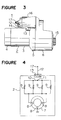
- FIG. 3 is a side view of a starter motor wherein a lead wire is led from a direct current motor portion to outside thereof.
- a reference numeral 1 designates a starter motor composed as follows.
- a numeral 2 designates a DC motor, wherein a rear bracket 4 is connected to a rear end of a yoke 3 and a front bracket 6 is connected to a front end thereof through an intermediate bracket 5. Inside thereof, a speed reducing gear device is connected to an armature and a pinion 15 is extended therefrom through an overrunning clutch.
- a numeral 16 designates an electromagnetic switch wherein a lead wire 12 extended from the motor 2 to outside thereof, is connected to a main circuit terminal (M terminal) 17.
- a numeral 13 designates a grommet fitted to a cut-off portion of the yoke 3 through which the lead wire 12 passes and 14, an insulation tube fitted to the lead wire 12.
- a circuit diagram of the DC motor 2 is shown by Figure 4.
- a numeral 7 designates an armature, 8, a brush and 9, a field coil to a connection conductor 10 of which the lead wire 12 is connected at a connecting portion 11.
- Figure 5A is a sectional diagram of a conventional leading-out device for a lead wire.
- An end of the lead wire 12 composed of twisted wires is connected to the connecting portion 11 of the connecting conductor 10 of the motor 2 by a brasing material.
- a lead wire 12 passing through the grommet 13 made of a gummy material is a twisted-wire conductor composed of a great number of copper wires.
- the starter motor since a large current flows in the lead wire 12 and in view of the vibration resistance, the diameter thereof is magnified.
- the outer configuration of a lead wire 12 is circular and thick.
- the lead wire 12 reaches inside of the yoke 3 through the grommet 13.
- the motor 2 is elongated in the axial direction, which hampers the downsizing thereof.
- a leading-out device for a lead wire of a DC motor comprising: a lead wire composed of twisted wires, a leading-out portion at an end side of which is formed in a flat shape and is shortened with respect to the axial direction of a DC motor; and a grommet through which said lead wire passes from outside the DC motor to inside thereof; said leading-out portion of the lead wire is welded and connected to an inner conductor of the DC motor at an end portion thereof.
- a method of leading out a lead wire of a DC motor comprising the steps of: forming a leading-out portion of a lead wire at an end side thereof composed of twisted wires in a flat shape by a resistance welding or an ultrasonic welding along with a brazing material; passing said leading-out portion of the lead wire through a grommet from outside the DC motor to inside thereof while aligning a shortening direction of the flat shape with the axial direction of the DC motor; and welding and connecting an end portion of the leading-out portion to an inner conductor by a resistance welding.
- a leading-out device for a lead wire of a DC motor comprising: a lead wire composed of twisted wires, a section of a leading-out portion at a first end side of which is formed in a rectangular shape shortened with respect to the axial direction of a DC motor, an upper portion of said leading-out portion being bent in an arcuate shape, a section of said bent portion at a second end side thereof being formed and reduced in a rectangular shape; and a grommet integrally formed with and surrounding the leading-out portion and the bent portion and fitted to a leading-out opening of the DC motor for the lead wire.
- the leading-out device for a lead wire of a DC motor according to the third aspect or the fourth aspect, wherein the grommet is laminated with a forming material the same with or different from a material for a portion surrounding the leading-out portion of the lead wire.
- the grommet is integrally formed with the deformed and reduced leading-out portion on the one end side of the lead wire. The operation of passing the leading-out portion through the grommet is saved. The protruding length of the leading-out portion of the lead wire from the grommet is set to a predetermined length. Furthermore, the invasion of the outside moisture is firmly prevented.
- FIG 1A is a sectional diagram of a first embodiment of a leading-out device for a lead wire of a DC motor according to the present invention.
- a leading-out portion of a lead wire 11 composed of twisted wires at an end side thereof passing through the grommet 13 is formed in a semicircular flattened form, shortened with respect to the axial direction of the motor 2 and widened in the peripheral direction thereof. Accordingly, as the grommet 13, the one which is shortened with respect to the axial direction of the motor 2 is employed.
- the flattening-deformation of the leading-out portion 21a of the lead wire 21 and the connection of the lead wire 21 to the inner conductor 10, are performed as follows.
- the leading-out portion of the lead wire 11 is pressed and deformed as shown in Figure 1B by a resistance welding along with a brazing material.
- the end portion of the leading-out portion 21a is connected to the connecting portion 11 of the inner conductor 10 by a resistance welding.
- the leading-out portion 21a already contains the brazing material and therefore, the addition of the brazing material is not necessary.
- the lead wire 21 is compressed in a flattened shape containing the brazing material at the grommet 13 and therefore, is excellent in the waterproof performance.
- the flattening-deformation of the lead wire 21 is performed by the resistance welding, but it may be performed by the following way.
- the leading-out portion 21a of the lead wire 21 composed of twisted wires is pressed and deformed in a flattened shape by an ultrasonic welding along with a brazing material. Thereafter, the leading-out portion 21a is connected to the inner conductor 10 by a resistance welding. According to this method of connecting the leading-out portion, the productivity is further promoted compared with the connection method in Example 1.
- the flattened shape of the leading-out portion 21a of the lead wire 21 is semicircular or rectangular.
- the shape is not limited to the above Examples and may be oval or trapezoidal.
- the leading-out portion of the lead wire composed of twisted wires is pressed and deformed in a flattened shape which is shortened with respect to the axial direction of the motor, the outer configuration with respect to the axial direction of the motor is shortened and downsized.
- FIG. 7A is a sectional diagram showing a fifth embodiment of a leading-out device for a lead wire according to the present invention.
- a coating layer 123 is integrally formed on the outer periphery of the leading-out portion 121a at an end side of the lead wire 21 wherein the section thereof is reduced and formed into a rectangular shape, by a mold (not shown) employing a heat-resistant gum such as polybutylene terephthalate (PBT).
- PBT polybutylene terephthalate
- the grommet 24 is integrally formed with an end side of the as coated lead wire 21 by a mold (not shown) employing a synthetic gum, a synthetic resin series gum, a thermoplastic elastomer or the like. In this way, the thermal resistance is promoted.
- the device can meet the required function by employing a gummy material corresponding to the requirement for the coating layer 123 and by laminating at least two kinds of forming materials for the coating layer 123 and the grommet 24.
- the leading-out portion at one end side of the lead wire is deformed in a rectangular form flattened with respect to the axial direction of the motor and the grommet is integrally formed with the one end side of the lead wire. Therefore, the integration operational performance is promoted, the waterproof can firmly be maintained and the protruding length of the leading-out portion from the grommet can be determined in a predetermined length. Moreover, in case of bending a portion of the lead wire above the leading-out portions, by providing the constricted portion at the other end of the bent portion which is reduced and deformed in a rectangular shape , the bent state of the lead wire is maintained and the integral forming of the grommet at the one side can easily be performed. Furthermore, the required performance can be promoted by forming the grommet by laminating at least two kinds of gummy materials at the leading-out portion of the lead wire.
Landscapes
- Engineering & Computer Science (AREA)
- Chemical & Material Sciences (AREA)
- Combustion & Propulsion (AREA)
- Mechanical Engineering (AREA)
- General Engineering & Computer Science (AREA)
- Power Engineering (AREA)
- Motor Or Generator Frames (AREA)
Applications Claiming Priority (4)
| Application Number | Priority Date | Filing Date | Title |
|---|---|---|---|
| JP4045898A JP3063932B2 (ja) | 1992-01-31 | 1992-01-31 | 直流電動機のリード線口出装置 |
| JP45898/92 | 1992-01-31 | ||
| JP146321/92 | 1992-05-12 | ||
| JP14632192A JP2866529B2 (ja) | 1992-05-12 | 1992-05-12 | 直流電動機のリード線口出装置 |
Publications (3)
| Publication Number | Publication Date |
|---|---|
| EP0553811A2 true EP0553811A2 (de) | 1993-08-04 |
| EP0553811A3 EP0553811A3 (en) | 1993-12-08 |
| EP0553811B1 EP0553811B1 (de) | 1996-11-20 |
Family
ID=26385994
Family Applications (1)
| Application Number | Title | Priority Date | Filing Date |
|---|---|---|---|
| EP93101308A Expired - Lifetime EP0553811B1 (de) | 1992-01-31 | 1993-01-28 | Anschlussvorrichtung für einen Anschlussdraht eines Gleichstrommotors und Verfahren zum Anschliessen eines Anschlussdrahtes |
Country Status (4)
| Country | Link |
|---|---|
| US (1) | US5309054A (de) |
| EP (1) | EP0553811B1 (de) |
| DE (1) | DE69306004T2 (de) |
| HK (1) | HK1002417A1 (de) |
Cited By (3)
| Publication number | Priority date | Publication date | Assignee | Title |
|---|---|---|---|---|
| EP0642205A3 (de) * | 1993-09-08 | 1995-07-19 | Electrolux Corp | Verbindung einer Anschlusslitze einer Bürste in einem elektrischen Motor. |
| WO1996031936A1 (en) * | 1995-04-03 | 1996-10-10 | E.I. Du Pont De Nemours And Company | Injection molded motor assembly and method of fabrication |
| EP0855783A3 (de) * | 1997-01-28 | 1999-10-13 | Mitsubishi Denki Kabushiki Kaisha | Anschlussvorrichtung für einen Anschlussdraht eines Elektromotors |
Families Citing this family (7)
| Publication number | Priority date | Publication date | Assignee | Title |
|---|---|---|---|---|
| JP3551897B2 (ja) * | 2000-06-09 | 2004-08-11 | 株式会社日立製作所 | 回転電機及び給電用リード線接続方法 |
| JP2002262510A (ja) * | 2001-03-01 | 2002-09-13 | Denso Corp | スタータのリード線組付け方法 |
| JP4687439B2 (ja) * | 2005-12-16 | 2011-05-25 | 株式会社デンソー | 回転電機 |
| US8669681B2 (en) | 2010-05-12 | 2014-03-11 | GM Global Technology Operations LLC | Conductive connection for bar-wound stators |
| ITBO20120682A1 (it) * | 2012-12-18 | 2014-06-19 | Spal Automotive Srl | Macchina elettrica |
| WO2019054090A1 (ja) * | 2017-09-15 | 2019-03-21 | 日本電産株式会社 | モータ及び電動パワーステアリング装置 |
| CN109510361B (zh) * | 2018-12-27 | 2024-02-02 | 长沙理工大学 | 一种三相异步发电机定子引出线连接结构 |
Family Cites Families (6)
| Publication number | Priority date | Publication date | Assignee | Title |
|---|---|---|---|---|
| US3839596A (en) * | 1973-05-07 | 1974-10-01 | Amp Inc | Flexible airtight stranded wire |
| US4315175A (en) * | 1975-06-30 | 1982-02-09 | General Electric Company | Aluminum-to-copper transition member for aluminum wound motors and aluminum wound motor equipped with the same |
| JPS60186852U (ja) * | 1984-05-17 | 1985-12-11 | 三菱電機株式会社 | 電動機の防水装置 |
| JPH0811031Y2 (ja) * | 1986-03-05 | 1996-03-29 | 三菱電機株式会社 | ブラシ装置 |
| US4712029A (en) * | 1986-12-22 | 1987-12-08 | Sundstrand Corporation | Generator high temperature electrical lead assembly |
| JPH0717255Y2 (ja) * | 1988-11-26 | 1995-04-19 | 三菱電機株式会社 | モータのブラシ装置 |
-
1993
- 1993-01-27 US US07/009,676 patent/US5309054A/en not_active Expired - Lifetime
- 1993-01-28 DE DE69306004T patent/DE69306004T2/de not_active Expired - Lifetime
- 1993-01-28 EP EP93101308A patent/EP0553811B1/de not_active Expired - Lifetime
-
1998
- 1998-01-22 HK HK98100583A patent/HK1002417A1/en not_active IP Right Cessation
Cited By (6)
| Publication number | Priority date | Publication date | Assignee | Title |
|---|---|---|---|---|
| EP0642205A3 (de) * | 1993-09-08 | 1995-07-19 | Electrolux Corp | Verbindung einer Anschlusslitze einer Bürste in einem elektrischen Motor. |
| US5465016A (en) * | 1993-09-08 | 1995-11-07 | Electrolux Corporation | Electric motor and brush/shunt assembly therefor |
| WO1996031936A1 (en) * | 1995-04-03 | 1996-10-10 | E.I. Du Pont De Nemours And Company | Injection molded motor assembly and method of fabrication |
| US5806169A (en) * | 1995-04-03 | 1998-09-15 | Trago; Bradley A. | Method of fabricating an injected molded motor assembly |
| US6020661A (en) * | 1995-04-03 | 2000-02-01 | Pacific Scientific Company | Injection molded motor assembly |
| EP0855783A3 (de) * | 1997-01-28 | 1999-10-13 | Mitsubishi Denki Kabushiki Kaisha | Anschlussvorrichtung für einen Anschlussdraht eines Elektromotors |
Also Published As
| Publication number | Publication date |
|---|---|
| EP0553811A3 (en) | 1993-12-08 |
| EP0553811B1 (de) | 1996-11-20 |
| HK1002417A1 (en) | 1998-08-21 |
| DE69306004D1 (de) | 1997-01-02 |
| US5309054A (en) | 1994-05-03 |
| DE69306004T2 (de) | 1997-04-10 |
Similar Documents
| Publication | Publication Date | Title |
|---|---|---|
| JP3701639B2 (ja) | 電動機のリードフレーム及びこれを用いた配電部品 | |
| US6528731B2 (en) | Flat shield harness and method for manufacturing the same | |
| US6028383A (en) | Resolver stator structure having insulation extended portion with connector pins | |
| EP0553811A2 (de) | Anschlussvorrichtung für einen Anschlussdraht eines Gleichstrommotors und Verfahren zum Anschliessen eines Anschlussdrahtes | |
| US4521710A (en) | Commutator device for miniature motors | |
| JP2006040624A (ja) | 異種電線間の接続構造 | |
| HK1002417B (en) | A leading-out device for a lead wire of a dc motor and a method of leading out a lead wire | |
| EP2166651A2 (de) | Elektrischer Motor und Verfahren zu seiner Herstellung | |
| JPH0560772A (ja) | センサの製造法及び該方法により製造されたセンサ | |
| CN112968563A (zh) | 旋转电机及其制造方法 | |
| JP4111053B2 (ja) | スタータ | |
| US20020121019A1 (en) | Method of assembling starter lead wire | |
| JP3063932B2 (ja) | 直流電動機のリード線口出装置 | |
| JP2866529B2 (ja) | 直流電動機のリード線口出装置 | |
| JPH0687638B2 (ja) | モ−タの端子装置 | |
| JP2002136027A (ja) | 電磁機器 | |
| WO2022059356A1 (ja) | ワイヤハーネス | |
| JPH0214298Y2 (de) | ||
| JP3198565B2 (ja) | スタータ用モータ | |
| JP5257242B2 (ja) | コイル装置及びその製造方法 | |
| JP7774498B2 (ja) | 回転電機のステータ構造 | |
| JP2004342761A (ja) | コイル装置 | |
| JP2003124043A (ja) | 点火コイル | |
| JPS595955Y2 (ja) | 点火コイル用ボビン | |
| JP3517910B2 (ja) | 電動機の固定子 |
Legal Events
| Date | Code | Title | Description |
|---|---|---|---|
| PUAI | Public reference made under article 153(3) epc to a published international application that has entered the european phase |
Free format text: ORIGINAL CODE: 0009012 |
|
| AK | Designated contracting states |
Kind code of ref document: A2 Designated state(s): DE FR GB IT |
|
| PUAL | Search report despatched |
Free format text: ORIGINAL CODE: 0009013 |
|
| AK | Designated contracting states |
Kind code of ref document: A3 Designated state(s): DE FR GB IT |
|
| 17P | Request for examination filed |
Effective date: 19940418 |
|
| 17Q | First examination report despatched |
Effective date: 19950214 |
|
| GRAG | Despatch of communication of intention to grant |
Free format text: ORIGINAL CODE: EPIDOS AGRA |
|
| GRAH | Despatch of communication of intention to grant a patent |
Free format text: ORIGINAL CODE: EPIDOS IGRA |
|
| GRAH | Despatch of communication of intention to grant a patent |
Free format text: ORIGINAL CODE: EPIDOS IGRA |
|
| GRAA | (expected) grant |
Free format text: ORIGINAL CODE: 0009210 |
|
| AK | Designated contracting states |
Kind code of ref document: B1 Designated state(s): DE FR GB IT |
|
| ITF | It: translation for a ep patent filed | ||
| ET | Fr: translation filed | ||
| REF | Corresponds to: |
Ref document number: 69306004 Country of ref document: DE Date of ref document: 19970102 |
|
| PLBE | No opposition filed within time limit |
Free format text: ORIGINAL CODE: 0009261 |
|
| STAA | Information on the status of an ep patent application or granted ep patent |
Free format text: STATUS: NO OPPOSITION FILED WITHIN TIME LIMIT |
|
| 26N | No opposition filed | ||
| REG | Reference to a national code |
Ref country code: GB Ref legal event code: IF02 |
|
| PGFP | Annual fee paid to national office [announced via postgrant information from national office to epo] |
Ref country code: FR Payment date: 20120202 Year of fee payment: 20 |
|
| PGFP | Annual fee paid to national office [announced via postgrant information from national office to epo] |
Ref country code: DE Payment date: 20120125 Year of fee payment: 20 |
|
| PGFP | Annual fee paid to national office [announced via postgrant information from national office to epo] |
Ref country code: GB Payment date: 20120125 Year of fee payment: 20 Ref country code: IT Payment date: 20120117 Year of fee payment: 20 |
|
| REG | Reference to a national code |
Ref country code: DE Ref legal event code: R071 Ref document number: 69306004 Country of ref document: DE |
|
| REG | Reference to a national code |
Ref country code: GB Ref legal event code: PE20 Expiry date: 20130127 |
|
| PG25 | Lapsed in a contracting state [announced via postgrant information from national office to epo] |
Ref country code: DE Free format text: LAPSE BECAUSE OF EXPIRATION OF PROTECTION Effective date: 20130129 Ref country code: GB Free format text: LAPSE BECAUSE OF EXPIRATION OF PROTECTION Effective date: 20130127 |