EP0554236B1 - Formage de nattes en deux étapes et préformage - Google Patents
Formage de nattes en deux étapes et préformage Download PDFInfo
- Publication number
- EP0554236B1 EP0554236B1 EP93890006A EP93890006A EP0554236B1 EP 0554236 B1 EP0554236 B1 EP 0554236B1 EP 93890006 A EP93890006 A EP 93890006A EP 93890006 A EP93890006 A EP 93890006A EP 0554236 B1 EP0554236 B1 EP 0554236B1
- Authority
- EP
- European Patent Office
- Prior art keywords
- binder
- preform
- mat
- mold
- stage
- Prior art date
- Legal status (The legal status is an assumption and is not a legal conclusion. Google has not performed a legal analysis and makes no representation as to the accuracy of the status listed.)
- Expired - Lifetime
Links
- 239000011230 binding agent Substances 0.000 claims abstract description 121
- 238000000034 method Methods 0.000 claims abstract description 50
- 239000003365 glass fiber Substances 0.000 claims abstract description 35
- 239000000835 fiber Substances 0.000 claims abstract description 26
- 239000000463 material Substances 0.000 claims description 35
- 230000002787 reinforcement Effects 0.000 claims description 20
- 238000004519 manufacturing process Methods 0.000 claims description 15
- 239000000470 constituent Substances 0.000 claims description 13
- 239000004033 plastic Substances 0.000 claims description 10
- 229920003023 plastic Polymers 0.000 claims description 10
- 238000004132 cross linking Methods 0.000 claims description 9
- 238000003825 pressing Methods 0.000 claims description 9
- 238000002156 mixing Methods 0.000 claims description 4
- 125000002091 cationic group Chemical group 0.000 claims description 3
- 239000003999 initiator Substances 0.000 claims description 2
- 229920002430 Fibre-reinforced plastic Polymers 0.000 claims 1
- 239000011151 fibre-reinforced plastic Substances 0.000 claims 1
- 230000008569 process Effects 0.000 abstract description 38
- 238000000465 moulding Methods 0.000 abstract description 12
- 150000003254 radicals Chemical class 0.000 abstract description 9
- 230000005855 radiation Effects 0.000 abstract description 4
- 239000007795 chemical reaction product Substances 0.000 abstract description 3
- 239000007787 solid Substances 0.000 abstract 1
- 239000011347 resin Substances 0.000 description 19
- 229920005989 resin Polymers 0.000 description 19
- 239000000047 product Substances 0.000 description 10
- 239000012779 reinforcing material Substances 0.000 description 10
- 230000006835 compression Effects 0.000 description 9
- 238000007906 compression Methods 0.000 description 9
- 238000006243 chemical reaction Methods 0.000 description 8
- 239000011159 matrix material Substances 0.000 description 7
- 230000008901 benefit Effects 0.000 description 5
- 239000010408 film Substances 0.000 description 5
- 239000003039 volatile agent Substances 0.000 description 4
- 230000004913 activation Effects 0.000 description 3
- 238000011109 contamination Methods 0.000 description 3
- 230000004048 modification Effects 0.000 description 3
- 238000012986 modification Methods 0.000 description 3
- NIXOWILDQLNWCW-UHFFFAOYSA-N acrylic acid group Chemical group C(C=C)(=O)O NIXOWILDQLNWCW-UHFFFAOYSA-N 0.000 description 2
- 230000005540 biological transmission Effects 0.000 description 2
- 238000003490 calendering Methods 0.000 description 2
- 239000002131 composite material Substances 0.000 description 2
- 238000010276 construction Methods 0.000 description 2
- 238000001035 drying Methods 0.000 description 2
- 238000011049 filling Methods 0.000 description 2
- 239000003574 free electron Substances 0.000 description 2
- 239000011521 glass Substances 0.000 description 2
- 238000010438 heat treatment Methods 0.000 description 2
- 239000007788 liquid Substances 0.000 description 2
- 239000002184 metal Substances 0.000 description 2
- -1 polyacrylics Polymers 0.000 description 2
- 239000012783 reinforcing fiber Substances 0.000 description 2
- 238000001228 spectrum Methods 0.000 description 2
- 238000005507 spraying Methods 0.000 description 2
- XLYOFNOQVPJJNP-UHFFFAOYSA-N water Substances O XLYOFNOQVPJJNP-UHFFFAOYSA-N 0.000 description 2
- XZMCDFZZKTWFGF-UHFFFAOYSA-N Cyanamide Chemical compound NC#N XZMCDFZZKTWFGF-UHFFFAOYSA-N 0.000 description 1
- 239000004705 High-molecular-weight polyethylene Substances 0.000 description 1
- OWYWGLHRNBIFJP-UHFFFAOYSA-N Ipazine Chemical compound CCN(CC)C1=NC(Cl)=NC(NC(C)C)=N1 OWYWGLHRNBIFJP-UHFFFAOYSA-N 0.000 description 1
- 239000004698 Polyethylene Substances 0.000 description 1
- 229910000831 Steel Inorganic materials 0.000 description 1
- 239000004699 Ultra-high molecular weight polyethylene Substances 0.000 description 1
- KQNZLOUWXSAZGD-UHFFFAOYSA-N benzylperoxymethylbenzene Chemical compound C=1C=CC=CC=1COOCC1=CC=CC=C1 KQNZLOUWXSAZGD-UHFFFAOYSA-N 0.000 description 1
- 230000015572 biosynthetic process Effects 0.000 description 1
- 239000006229 carbon black Substances 0.000 description 1
- 239000011248 coating agent Substances 0.000 description 1
- 238000000576 coating method Methods 0.000 description 1
- 238000001816 cooling Methods 0.000 description 1
- 238000005520 cutting process Methods 0.000 description 1
- 239000000839 emulsion Substances 0.000 description 1
- 238000005516 engineering process Methods 0.000 description 1
- 230000007613 environmental effect Effects 0.000 description 1
- 150000002118 epoxides Chemical class 0.000 description 1
- 239000002657 fibrous material Substances 0.000 description 1
- 239000012467 final product Substances 0.000 description 1
- 230000000977 initiatory effect Effects 0.000 description 1
- 238000002347 injection Methods 0.000 description 1
- 239000007924 injection Substances 0.000 description 1
- 230000007246 mechanism Effects 0.000 description 1
- 238000002844 melting Methods 0.000 description 1
- 230000008018 melting Effects 0.000 description 1
- 230000008520 organization Effects 0.000 description 1
- 230000000149 penetrating effect Effects 0.000 description 1
- 229920000728 polyester Polymers 0.000 description 1
- 229920000573 polyethylene Polymers 0.000 description 1
- 229920000642 polymer Polymers 0.000 description 1
- 238000006116 polymerization reaction Methods 0.000 description 1
- 229920002635 polyurethane Polymers 0.000 description 1
- 239000004814 polyurethane Substances 0.000 description 1
- 239000004800 polyvinyl chloride Substances 0.000 description 1
- 229920000915 polyvinyl chloride Polymers 0.000 description 1
- 239000000843 powder Substances 0.000 description 1
- 238000002360 preparation method Methods 0.000 description 1
- 230000001737 promoting effect Effects 0.000 description 1
- 239000010453 quartz Substances 0.000 description 1
- 230000009467 reduction Effects 0.000 description 1
- 230000003014 reinforcing effect Effects 0.000 description 1
- 238000005096 rolling process Methods 0.000 description 1
- VYPSYNLAJGMNEJ-UHFFFAOYSA-N silicon dioxide Inorganic materials O=[Si]=O VYPSYNLAJGMNEJ-UHFFFAOYSA-N 0.000 description 1
- 239000002904 solvent Substances 0.000 description 1
- 239000007921 spray Substances 0.000 description 1
- 239000010959 steel Substances 0.000 description 1
- 238000003860 storage Methods 0.000 description 1
- GJBRNHKUVLOCEB-UHFFFAOYSA-N tert-butyl benzenecarboperoxoate Chemical compound CC(C)(C)OOC(=O)C1=CC=CC=C1 GJBRNHKUVLOCEB-UHFFFAOYSA-N 0.000 description 1
- BWSZXUOMATYHHI-UHFFFAOYSA-N tert-butyl octaneperoxoate Chemical compound CCCCCCCC(=O)OOC(C)(C)C BWSZXUOMATYHHI-UHFFFAOYSA-N 0.000 description 1
- 239000010409 thin film Substances 0.000 description 1
- 239000012780 transparent material Substances 0.000 description 1
- 229920000785 ultra high molecular weight polyethylene Polymers 0.000 description 1
- 229920006305 unsaturated polyester Polymers 0.000 description 1
- 238000009736 wetting Methods 0.000 description 1
- 238000004804 winding Methods 0.000 description 1
- 239000002023 wood Substances 0.000 description 1
Images
Classifications
-
- C—CHEMISTRY; METALLURGY
- C03—GLASS; MINERAL OR SLAG WOOL
- C03B—MANUFACTURE, SHAPING, OR SUPPLEMENTARY PROCESSES
- C03B37/00—Manufacture or treatment of flakes, fibres, or filaments from softened glass, minerals, or slags
-
- C—CHEMISTRY; METALLURGY
- C08—ORGANIC MACROMOLECULAR COMPOUNDS; THEIR PREPARATION OR CHEMICAL WORKING-UP; COMPOSITIONS BASED THEREON
- C08J—WORKING-UP; GENERAL PROCESSES OF COMPOUNDING; AFTER-TREATMENT NOT COVERED BY SUBCLASSES C08B, C08C, C08F, C08G or C08H
- C08J3/00—Processes of treating or compounding macromolecular substances
- C08J3/24—Crosslinking, e.g. vulcanising, of macromolecules
- C08J3/243—Two or more independent types of crosslinking for one or more polymers
-
- B—PERFORMING OPERATIONS; TRANSPORTING
- B29—WORKING OF PLASTICS; WORKING OF SUBSTANCES IN A PLASTIC STATE IN GENERAL
- B29C—SHAPING OR JOINING OF PLASTICS; SHAPING OF MATERIAL IN A PLASTIC STATE, NOT OTHERWISE PROVIDED FOR; AFTER-TREATMENT OF THE SHAPED PRODUCTS, e.g. REPAIRING
- B29C70/00—Shaping composites, i.e. plastics material comprising reinforcements, fillers or preformed parts, e.g. inserts
- B29C70/04—Shaping composites, i.e. plastics material comprising reinforcements, fillers or preformed parts, e.g. inserts comprising reinforcements only, e.g. self-reinforcing plastics
- B29C70/28—Shaping operations therefor
- B29C70/30—Shaping by lay-up, i.e. applying fibres, tape or broadsheet on a mould, former or core; Shaping by spray-up, i.e. spraying of fibres on a mould, former or core
- B29C70/34—Shaping by lay-up, i.e. applying fibres, tape or broadsheet on a mould, former or core; Shaping by spray-up, i.e. spraying of fibres on a mould, former or core and shaping or impregnating by compression, i.e. combined with compressing after the lay-up operation
- B29C70/345—Shaping by lay-up, i.e. applying fibres, tape or broadsheet on a mould, former or core; Shaping by spray-up, i.e. spraying of fibres on a mould, former or core and shaping or impregnating by compression, i.e. combined with compressing after the lay-up operation using matched moulds
-
- B—PERFORMING OPERATIONS; TRANSPORTING
- B29—WORKING OF PLASTICS; WORKING OF SUBSTANCES IN A PLASTIC STATE IN GENERAL
- B29C—SHAPING OR JOINING OF PLASTICS; SHAPING OF MATERIAL IN A PLASTIC STATE, NOT OTHERWISE PROVIDED FOR; AFTER-TREATMENT OF THE SHAPED PRODUCTS, e.g. REPAIRING
- B29C70/00—Shaping composites, i.e. plastics material comprising reinforcements, fillers or preformed parts, e.g. inserts
- B29C70/04—Shaping composites, i.e. plastics material comprising reinforcements, fillers or preformed parts, e.g. inserts comprising reinforcements only, e.g. self-reinforcing plastics
- B29C70/28—Shaping operations therefor
- B29C70/40—Shaping or impregnating by compression not applied
- B29C70/50—Shaping or impregnating by compression not applied for producing articles of indefinite length, e.g. prepregs, sheet moulding compounds [SMC] or cross moulding compounds [XMC]
-
- B—PERFORMING OPERATIONS; TRANSPORTING
- B29—WORKING OF PLASTICS; WORKING OF SUBSTANCES IN A PLASTIC STATE IN GENERAL
- B29C—SHAPING OR JOINING OF PLASTICS; SHAPING OF MATERIAL IN A PLASTIC STATE, NOT OTHERWISE PROVIDED FOR; AFTER-TREATMENT OF THE SHAPED PRODUCTS, e.g. REPAIRING
- B29C70/00—Shaping composites, i.e. plastics material comprising reinforcements, fillers or preformed parts, e.g. inserts
- B29C70/04—Shaping composites, i.e. plastics material comprising reinforcements, fillers or preformed parts, e.g. inserts comprising reinforcements only, e.g. self-reinforcing plastics
- B29C70/28—Shaping operations therefor
- B29C70/54—Component parts, details or accessories; Auxiliary operations, e.g. feeding or storage of prepregs or SMC after impregnation or during ageing
- B29C70/543—Fixing the position or configuration of fibrous reinforcements before or during moulding
-
- B—PERFORMING OPERATIONS; TRANSPORTING
- B29—WORKING OF PLASTICS; WORKING OF SUBSTANCES IN A PLASTIC STATE IN GENERAL
- B29C—SHAPING OR JOINING OF PLASTICS; SHAPING OF MATERIAL IN A PLASTIC STATE, NOT OTHERWISE PROVIDED FOR; AFTER-TREATMENT OF THE SHAPED PRODUCTS, e.g. REPAIRING
- B29C43/00—Compression moulding, i.e. applying external pressure to flow the moulding material; Apparatus therefor
- B29C43/02—Compression moulding, i.e. applying external pressure to flow the moulding material; Apparatus therefor of articles of definite length, i.e. discrete articles
- B29C43/04—Compression moulding, i.e. applying external pressure to flow the moulding material; Apparatus therefor of articles of definite length, i.e. discrete articles using movable moulds
-
- B—PERFORMING OPERATIONS; TRANSPORTING
- B29—WORKING OF PLASTICS; WORKING OF SUBSTANCES IN A PLASTIC STATE IN GENERAL
- B29C—SHAPING OR JOINING OF PLASTICS; SHAPING OF MATERIAL IN A PLASTIC STATE, NOT OTHERWISE PROVIDED FOR; AFTER-TREATMENT OF THE SHAPED PRODUCTS, e.g. REPAIRING
- B29C43/00—Compression moulding, i.e. applying external pressure to flow the moulding material; Apparatus therefor
- B29C43/02—Compression moulding, i.e. applying external pressure to flow the moulding material; Apparatus therefor of articles of definite length, i.e. discrete articles
- B29C43/14—Compression moulding, i.e. applying external pressure to flow the moulding material; Apparatus therefor of articles of definite length, i.e. discrete articles in several steps
-
- B—PERFORMING OPERATIONS; TRANSPORTING
- B29—WORKING OF PLASTICS; WORKING OF SUBSTANCES IN A PLASTIC STATE IN GENERAL
- B29K—INDEXING SCHEME ASSOCIATED WITH SUBCLASSES B29B, B29C OR B29D, RELATING TO MOULDING MATERIALS OR TO MATERIALS FOR MOULDS, REINFORCEMENTS, FILLERS OR PREFORMED PARTS, e.g. INSERTS
- B29K2105/00—Condition, form or state of moulded material or of the material to be shaped
- B29K2105/24—Condition, form or state of moulded material or of the material to be shaped crosslinked or vulcanised
-
- B—PERFORMING OPERATIONS; TRANSPORTING
- B29—WORKING OF PLASTICS; WORKING OF SUBSTANCES IN A PLASTIC STATE IN GENERAL
- B29K—INDEXING SCHEME ASSOCIATED WITH SUBCLASSES B29B, B29C OR B29D, RELATING TO MOULDING MATERIALS OR TO MATERIALS FOR MOULDS, REINFORCEMENTS, FILLERS OR PREFORMED PARTS, e.g. INSERTS
- B29K2105/00—Condition, form or state of moulded material or of the material to be shaped
- B29K2105/24—Condition, form or state of moulded material or of the material to be shaped crosslinked or vulcanised
- B29K2105/243—Partially cured
-
- Y—GENERAL TAGGING OF NEW TECHNOLOGICAL DEVELOPMENTS; GENERAL TAGGING OF CROSS-SECTIONAL TECHNOLOGIES SPANNING OVER SEVERAL SECTIONS OF THE IPC; TECHNICAL SUBJECTS COVERED BY FORMER USPC CROSS-REFERENCE ART COLLECTIONS [XRACs] AND DIGESTS
- Y10—TECHNICAL SUBJECTS COVERED BY FORMER USPC
- Y10S—TECHNICAL SUBJECTS COVERED BY FORMER USPC CROSS-REFERENCE ART COLLECTIONS [XRACs] AND DIGESTS
- Y10S264/00—Plastic and nonmetallic article shaping or treating: processes
- Y10S264/59—Processes in which a partial cure is involved
-
- Y—GENERAL TAGGING OF NEW TECHNOLOGICAL DEVELOPMENTS; GENERAL TAGGING OF CROSS-SECTIONAL TECHNOLOGIES SPANNING OVER SEVERAL SECTIONS OF THE IPC; TECHNICAL SUBJECTS COVERED BY FORMER USPC CROSS-REFERENCE ART COLLECTIONS [XRACs] AND DIGESTS
- Y10—TECHNICAL SUBJECTS COVERED BY FORMER USPC
- Y10S—TECHNICAL SUBJECTS COVERED BY FORMER USPC CROSS-REFERENCE ART COLLECTIONS [XRACs] AND DIGESTS
- Y10S264/00—Plastic and nonmetallic article shaping or treating: processes
- Y10S264/66—Processes of reshaping and reforming
Definitions
- the present invention relates to a method for making a preform and to an apparatus for making a preform, for curing binders on non-woven reinforcing materials, woven reinforcing materials and combinations thereof during their manufacture, and is more particularly concerned with utilizing directed energy which is focused for reaction on a two-stage binder without involving the reinforcing materials to a significant degree.
- binders are usually dry, powder resins, but can be emulsions or liquids.
- the fiber materials are produced in a conventional manner for the type of construction desired. Normally, the binders are applied to the reinforcements and then subjected to heating, to melt, or dry-before-melt, and sometimes to cure the binders.
- the binder can be either unsaturated, cured or staged, depending on application requirements. In this connection, one may refer to U.S. 4 054 713 of Sakaguchi, et al.
- That object was achieved by providing a process and an apparatus for carrying out the process in which a layer of reinforcing fibers is formed on a travelling web, such as a conveyor belt, binder is applied to thinly coat the layer without filling the interstices between the fibers, for example by spraying or calendering, the binder-coated layer is compressed to a desired density/thickness ratio, and the binder is cured during compression. The resulting mat is then taken from the web and rolled up.
- the binder in that application was selected as an electromagnetically-curable binder, either an ultraviolet energy-curable binder or a microwave energy-curable binder. Accordingly, during curing, the corresponding ultraviolet or microwave energy is applied while the layer is compressed to the desired density/thickness ratio.
- ultraviolet is considered to be from deep UV ( ⁇ 200 nm) up to visible light ( ⁇ 450 nm). Combinations of wavelengths may be used to advantage in practicing the invention.
- the process and apparatus of the above-identified older development differs significantly from that heretofore known in the art in that directed energy is used to cure the special binders developed for the process, the binders being sensitive to the directed energy used, preferably microwave or ultraviolet.
- the binders can be cured on the fiber with directed energy without involving the mass of fibers in the energy of reaction.
- the binders are typically oligomers, unsaturated polyesters, epoxides, polyacrylics, polyurethanes, and the like. When cured, the binders have unsaturated sites available for subsequent bonding with matrix resins in subsequent molding processes such as RTM and SRIM processes. Using this process, the reinforcing material is primarily passive to the activation energy.
- the reaction takes place without involving the reinforcing materials since the activation energy is targeted only at the binder.
- the binders perform the same functions as in the conventional manufacturing systems, but can be cured much more rapidly, with significantly less energy and without producing significant volatiles that have to be collected to prevent contamination of the environment. Because there are basically no volatiles, there is little or no need to collect the volatiles driven off by heat, there is little or no need for make-up air and little or no need for make-up heat, thereby saving energy and thereby substantially avoiding contamination of the environment.
- the object and intention of the present invention is to provide a new method and a new apparatus for making preforms by using new binders for use with reinforcements such as glass fibers.
- this object is achieved by a method of making a preform comprising the steps of: mixing a two-stage binder including a first binder constituent which has a first initiator responsive to visible light or microwaves to generate free radicals which cross link and provide a viscosity sufficient to hold glass fibers together and a second binder constituent which has a cationic-type second photoinitiator responsive to another electromagnetic energy, such as ultraviolet light or microwave energy, to generate electrons for cross-linking and render the binder rigid; applying said two-stage binder to a mat of glass fiber reinforcement material sufficient to wet the fibers but insufficient to fill the interstices between the fibers; exposing the two-stage binder to visible light or microwaves to partially polymerize the binder such that it has a viscosity sufficient to hold the glass fibers together for subsequent handling; pressing the mat; and exposing the pressed mat to the other electromagnetic energy to activate the second photoinitiator and produce a rigid three-dimensional preformed mat.
- an apparatus for making a preform comprising in combination: means for mixing a two-stage binder including a first binder constituent which has a first photoinitiator responsive to visible light or microwaves to generate free radicals which cross-link and provide a viscosity sufficient to hold glass fibers together and a second binder constituent which has a cationic type second photoinitiator responsive to another elctromagnetic energy, such as ultraviolet light or microwave energy, to generate electrons for cross-linking and render the binder rigid; means for applying the two-stage binder to a mat of glass fiber reinforcement material in an amount sufficient to wet the glass fibers but insufficient to fill the interstices between the fibers; means for exposing the two-stage binder to visible light or microwaves to partially polymerize the binder such that it has viscosity sufficient to hold the glass fibers together for subsequent handling; means for pressing the mat into the desired shape; and an ultraviolet generation means for the other electromagnetic energy for exposing the pressed mat to the other electromagnetic energy to activate the
- the new binders are to be used to make mat-type products that will subsequently be used in the manufacture of preforms which, by definfition, are three-dimensional reinforcement shapes without matrix resins impregnated therein and are used in a molding process such as the RIM, RTM and SRIM molding processes.
- the binders can be used in varying ratios with respect to the weigth of the glass fiber material. Typical ratios according to the present invention will be on the order of 1 % by weight to 12 % by weight of the glass fiber material and it is preferred that the binder ratio will be in the range of 2 % to 8 % range.
- the binders are unique in that they will contain two separate photoinitiators that will function independently in initiating the reaction of the binder and such binders are considered as two-stage binders.
- the first stage includes a photoinitiator which is a free radical generator of the type provided by a number of materials such as Irgacure® 651, Irgacure® 184 or Irgacure® 907. (Irgacure® is a trademark of Ciba Geigy AG, Germany.)
- a photoinitiator which is a free radical generator of the type provided by a number of materials such as Irgacure® 651, Irgacure® 184 or Irgacure® 907.
- Irgacure® is a trademark of Ciba Geigy AG, Germany.
- the first stage which is responsive to provide a partial cure is responsive only to visible light and the remainder of the binder is uncured until such time that the same is used in making a preform and is only responsive to other electromagnetic energy, such as ultraviolet light or microwave energy.
- the first stage may be fashioned to be microwave driven, particularly if the mat manufacturer uses a binder containing moisture. Suitable materials as photoinitiators are Lupasol® 256 (trademark of BASF Aktiengesellschaft, Germany), benzylperoxide, tert-butylperoctoate and tert-butylperbenzoate.
- the first-stage constituent is employed in a predetermined ratio to the binder such that when exposed to visible light, a reaction will start using the free radicals being generated and cross linking will proceed until the free radicals are all linked or used up and the reaction will then stop.
- the ratio of first-stage photoinitiator to the binder resin and exposure to microwave drive or visible light which ever is appropriate, will determine the viscosity of the resulting partially-polymerized binder.
- the viscosity should be such that, when staged in this manner, the binder will have the viscosity raised to a point where it will hold the glass fibers together for handling, preferably tack-free, during subsequent processing.
- the binder will be plastic, deformable and not yet rigid enough to hold the three-dimensional shapes of preforms. In other words, it will be pliable for further handling and the interstices of the glass fibers are obviously not filled at this time as they will be later during the final molding process.
- the second stage constituent includes a photoinitiator that is a cationic type photoinitiator responsive to another electromagnetic energy, such as ultraviolet light or microwave energy, that will continue to provide electrons for cross linking as long as the second constituent is exposed, for example, to ultraviolet light in a predetermined portion of the ultroviolet spectrum.
- Typical photoinitiators of this portion of the reaction are Irgacure® 261, Cyracure® UVE 6990 and Cyracure® UVE 6974.
- the Irgacure® products are produced by Ciba Geigy Corp. of Greensborough, N.C. and Hawthorne N.Y.. Cyracure® is a trademark of American Cyanamid Corporation, Wayne, N.J.
- the second stage is now available to complete the cure and make the binder rigid which is advantageous from the point of having the mat pliable for use in molding equipment to make a preform.
- the second stage cure takes place after the mat product has been formed into its three-dimensional shape which is the shape determined as necessary to replicate the final product for the final molding operation.
- the second stage cure takes place by exposing the binder to ultraviolet light, for example, such as in the CompFormTM processes disclosed in prior applications, Serial No. 446 859, filed December 6, 1989 and 552 253, filed July 12, 1990.
- CompFormTM is a trademark of the C.A. Lawton Company, assignee of the present invention.
- the present process will permit the use of single end roving, such as PPG No. 2002, OCF 366, 107B or 30. This will provide a variety of yields with the yield selected in accordance with the binder resin makeup.
- the two-stage binder also eliminates the need for two separate applications of different binders when preforming using ultraviolet-cured binders for preforms as in the aforementioned CompFormTM processes.
- Current technology dictates that mat-type products are purchased with conventional binders applied thereto when they are produced.
- Conventional binders require modification with heat during preforming or their resilience must be overcome during preforming.
- New two-stage binders eliminate these problems by using a single binder resin with two photoinitiators.
- the first stage takes the place of the first binder as applied by the reinforcement manufacturer, i.e. the glass fiber manufacturer, and the second stage takes the place of the second binder applied by the preform manufacturer for use in preforming.
- the second stage cure requires less cross linking to obtain a final cure. This will speed up the second stage cure over that it would have been if there was no first stage cure.
- the free radicals generated in the first stage curing cross link with each other until there are no further free radicals.
- the free electrons are shared by the orbital rings for cross linking.
- binders are liquid, they do not need to be carried in water to be sprayed. Residual moisture in the reinforcing fibers has long been proven as a cause for reduction of physical and electrical properties with some matrix resins. Because there is no water in the system, there is no required drying and the just-mentioned problem is overcome. Curing by directed energy provides the necessary stiffness and material handling characteristics.
- Fiber mats come in two general categories, discontinuous fibers called chopped strand mat and continuous fibers generally called continuous strand mat. There are many styles to each of these types of mats.
- the fiber mats are prepared by the manufacturer, i.e. as a layer of fibers deposited on a moving web, as disclosed in the aforementioned U.S. 4 054 713 and in accordance with the present invention using a two-stage binder.
- the mats are prepared on a continuous web or belt and, upon completion of the layer formation, a binder is applied, typically by spraying, or it can be calendered. This is not a filling or impregnating step.
- the binder is applied in a range of 1 % - 12 % by weight of the glass fiber, typically and preferably in the range of 2.0 - 8.0 weight percent.
- a residence time to allow some wetting of the fibers can be provided by a transport distance to the compression and curing section of the production line as in the aformentioned application, published in US-PS 5 169 571.
- the intent of the present concept is to provide a new method and an apparatus for making a preform by using new binders for use with reinforcement material such as glass fiber.
- These new binders are to be used to make mat-type products that will then be used in the manufacture of preforms which as is well known in the art, are then used in the manufacture of impregnated finished articles such as bumper beams, sinks and the like.
- preforms are three-dimensional products which are used as a basis for making, and as a backbone for making a conforming three-dimensional finished RIM, RTM, SRIM, or similar molded product.
- the rollers can be made of porous metal screen that will allow light transmission or that they can be made of a light-transparent material, such as a light-transparent acrylic or of a light-transparent glass or quartz.
- the belt or web can be made of a porous flexible metal screen that will permit light transmission or it can be made of a light-transparent polymer belt or web, such as light-transparent polyethylene, light-transparent acrylic or light-transparent poly-vinylchloride.
- Transparency is relative to the portion of the spectrum in which one is operating.
- a light-transparent film can be employed as the web which would also act to keep the uncured binders from the surfaces of the rollers or belts, if desired. It would also keep the potentially-abrasive glass materials from wearing out the surfaces of the transport system.
- the light-transparent film can be left with the product as a layer separator in the rolls. A further use of this film then can be as a vacuum seal if desired in subsequent cutting or forming applications, such as in the aforementioned preform applications.
- the film can also be used as a release film during preforming processes of the type referenced above, when applicable or desired.
- a two-stage binder is employed in which the first stage constituent is responsive to visible light or microwaves to generate cross linking radicals and provide a viscosity sufficient to hold the glass fibers together for subsequent handling and the second stage constituent is responsive to another electromagnetic energy, such as ultraviolet light or microwave energy, and produces free electrons to be shared (cross-linked) between binder elements.
- Compression of the materials can be achieved by feeding the mats between two continuous belts or webs that maintain pressure while moving through the light sources. Rollers can be placed between or within the light sources transversely of the web to maintain pressure on the belts or webs.
- the pressure can also be maintained by having the belts or webs held together (pneumatically, hydraulically, springs, etc) and by having a continuous surface on each half of the waveguide in contact with the belt or web.
- This continuous surface will be made of a low-friction, low-loss material (in the case of microwave) such as high molecular weight polyethylene or ultra-high molecular weight polyethylene.
- the belt or web will be similar in material.
- the invention is applicable to the utilization of different forms of directed energy. Therefore, a detailed description of the use of visible and ultraviolet light responsive systems will be provided hereinbelow.
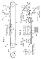
- a mat forming system is generally illustrated at 10 as comprising a plurality of stages spaced along a conveyor belt 12 which is supported for travel along a defined path by a pair of end rollers 14 and 16.
- the system includes a fiber preparation and application stage 18, a binder applicator 20 and a compression and curing stage 22.
- the formed mat is taken off and rolled up on a take-up or winding roller 52.
- reinforcement fibers for example either continuous strand or chopped glass fibers, are prepared in a manner known in the art, much am disclosed in the aforementioned U.S. 4,054,713, in the apparatus 24 and deposited, symbolically indicted by the arrow 26, onto the upper surface of the conveyor belt 12 as a layer 26' of fibers.
- the layer 26' of fibers is then received at the binder applicator station 20 in which binder is drawn from a supply 28, here a two-stage visible and ultraviolet light energy-curable binder, and applied by way of a sprayer 30 as a spray 32 onto the upper surface of the formed layer 26' to form a binder-coated layer 26 VL on the upper surface of the conveyor belt 12 with a 1.0---12.0 weight percent of binder, preferably 2.0--8.0 percent weight with respect to the glass fiber or other reinforcement material. It will therefore be appreciated that the binder is applied, not as a fill, but more as a thin penetrating random disposition of droplets.
- the binder-coated layer 26 VL then passes into the compression and curing stage 22 in which the conveyor belt 12, more particularly the layer 26 VL carried thereon is compressed between pairs of spaced compression rollers 34--38 where the layer 26 VL is compressed to a desired density/thickness ratio by the rollers, in stages, and the binder is cured, in stages, by way of the spaced visible light sources 42, 44 (or split microwave waveguides) which extend transversely of the layer 26 VL and radiate the same as indicated at 46, 48.
- the finished fiber mat, now referenced 50 UV is taken from the conveyor belt 12 and rolled up on the wind-up roller 52. The same is drawn from the roll and fed to the die cutter 54 of FIG. 2.
- the first step may be to precut a reinforcement material from the mat 50 UV to conform to the developed shape of a preform, as indicated by the die cutter 54. This is undertaken after the initial portion of the process set forth in FIG. 1.
- the composite blank of reinforcement material and binder is transported to a mold 56 by a robot 58.
- the mold may be of the type illustrated in FIG. 2 such that the composite blank is positioned on the male portion 56 of the mold as indicated at 60 of FIG. 2.
- the mold portion 56 is then moved along a shuttle 62 to a press 64 where the two halves of the mold are pressed together to replicate the desired shape of the preform and energy is applied from a directed energy source 86 such as a source of microwave or ultraviolet light energy.
- the mold is unloaded by moving the same along the shuttle 62 to a position where a robot 66 unloads the cured preform 68.
- the preform becomes a "carrier" preform in that reinforcement is to be added in the form of a reinforcing structure.
- the robot 66 will then stack the carrier preform for short term storage or move it directly into an energetic stitching process.
- the reinforcement material is precut, as before, at 70 and a robot 72 positions the precut material over a former 74 so that it takes a reinforcement shape 76.
- a robot 78 then retrieves the carrier preform 84, and places the same over the formed element 76.
- the carrier preform 68 and the formed element 76 engage in intimate contact.
- the element 76 comprises a binder resin.
- an ultraviolet sensitive binder resin is applied at specific spot locations where the elements 68 and 76 are in intimate engagement. Ultraviolet energy is then applied to cure and bond.
- a directed energy source 82 is then employed to cure the binder and bond the two elements together to form a reinforced structure 84.
- the structure 84 is then transferred to an RIM, RTM or SRIM molding process for molding of the finished structure.
- attachments may be bonded to a carrier preform to increase structural strength of the molded end product or to add attachment devices for the molded end product by the energetic stitching of elements to the preform. It is not necessary that one element to be attached to another be made by the same energy directed process, or at all by a particular energy directed process. One element may be attached to another by the application of a microwave-sensitive or ultraviolet-sensitive binder resin and the application of the corresponding energy to cure that binder resin. Therefore, this flexibility is an advantage of the energetic stitching process in that a preform made by the microwave technique may have a reinforcement element attached by energetic stitching using the ultraviolet technique and vice-versa. Also, elements such as wood, steel, carbon black and the like may be attached to a preform by using either technique in combination with the appropriate binder resin.
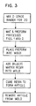
- the entire molding process is generally set forth in flow-chart style in which a two-stage binder is mixed for the binder applicator 20 of FIG. 1, the mat is formed according to FIG. 1 and a preform is formed according to FIG. 2.
- the preform is then placed into a mold, in accordance with RIM, RTM and SRIM processes and a deformable plastic material, such as a matrix resin is introduced into the mold, such as by injection, to flow the matrix resin into and fill the interstices of the preform.
- the mold may be a press mold and conforms to the article to be replicated.
- the matrix resin is then cured in the mold and the product is then removed according to standard molding processes.
Landscapes
- Chemical & Material Sciences (AREA)
- Engineering & Computer Science (AREA)
- Composite Materials (AREA)
- Mechanical Engineering (AREA)
- Organic Chemistry (AREA)
- Health & Medical Sciences (AREA)
- Chemical Kinetics & Catalysis (AREA)
- Medicinal Chemistry (AREA)
- Polymers & Plastics (AREA)
- Textile Engineering (AREA)
- Life Sciences & Earth Sciences (AREA)
- General Life Sciences & Earth Sciences (AREA)
- Geochemistry & Mineralogy (AREA)
- Manufacturing & Machinery (AREA)
- Materials Engineering (AREA)
- Reinforced Plastic Materials (AREA)
- Processing And Handling Of Plastics And Other Materials For Molding In General (AREA)
- Casting Or Compression Moulding Of Plastics Or The Like (AREA)
- Moulding By Coating Moulds (AREA)
- Blow-Moulding Or Thermoforming Of Plastics Or The Like (AREA)
- Polymerisation Methods In General (AREA)
Claims (10)
- Un procédé de fabrication d'une préforme comprenant les étapes consistant: à mélanger un liant à deux étapes comprenant un premier composant de liant, présentant un premier initiateur qui est sensible à la lumière visible ou aux micro-ondes pour générer des radicaux libres qui se réticulent et assurer une viscosité suffisante pour maintenir ensembles les fibres de verte, et un deuxième composant de liant présentant un deuxième photoinitiateur du type cationique, sensible à une autre énergie électromagnétique, telle que la lumière ultraviolette ou les micro-ondes, pour générer des électrons pour la réticulation, et pour rendre le liant rigide; à appliquer ledit liant à deux étapes à un mat de renforcement en fibre de verre de façon suffisante pour mouiller les fibres, mais insuffisante pour remplir les interstices entre les fibres; à exposer le liant à deux étapes à la lumière visible ou à des micro-ondes, afin de polymériser partiellement le liant, pour qu'il présente une viscosité suffisante pour maintenir les fibres de verre ensembles en vue de leur manipulation ultérieure; à comprimer le mat; et à exposer le mat comprimé à l'autre énergie électromagnétique, afin d'activer le deuxième photoinitiateur et de produire un mat préformé tridimensionnel et rigide.
- Un procédé de fabrication d'une préforme selon la revendication 1, comprenant l'étape consistant à comprimer le mat dans un moule ayant les dimensions voulues d'une préforme tridimensionnelle à réaliser, et à exposer ensuite le mat comprimé à travers le moule, afin d'activer le deuxième photoinitiateur, et de produire une préforme tridimensionnelle rigide.
- Un procédé de fabrication d'une préforme selon le la revendication 1, dans lequel on applique le liant à deux étapes aux fibres en une quantité allant de 2 à 8% en poids, basée sur le matériau en fibres de verre.
- Un procédé de fabrication d'une préforme selon la revendication 1, dans lequel on applique le liant à deux étapes aux fibres en une quantité allant de 1 à 12% en poids, basée sur le matériau en fibres de verre.
- Un procédé de fabrication d'un élément en matière synthétique renforcée par des fibres, dans lequel le procédé selon la revendication 2 est utilisé pour la fabrication d'une préforme, et dans lequel on place la préforme dans un deuxième moule, destiné à dupliquer un élément à former; on insère un matériau en plastique déformable dans le second moule avec la préforme; on comprime la préforme et le matériau plastique déformable dans le deuxième moule, afin de faire couler le matériau plastique, de manière à ce qu'il remplisse les interstices entre les fibres de verre de la préforme; on durcit le matériau plastique de façon à rigidifier la partie voulue; et on enlève du moule la partie voulue.
- Un appareil de fabrication d'une préforme comprenant, en combinaison:- des moyens pour mélanger un liant à deux étapes, comprenant un premier composant de liant, présentant un premier photoinitiateur qui est sensible à la lumière visible ou aux micro-ondes, pour générer des radicaux libres qui se réticulent et assurer une viscosité suffisante pour maintenir ensemble les fibres de verte, et un deuxième composant de liant présentant un deuxième photoinitiateur du type cationique, sensible à une autre énergie électromagnétique, telle que la lumière ultraviolette ou les micro-ondes, pour générer des électrons pour la réticulation, et pour rendre le liant rigide,des moyens pour appliquer en deux étapes le liant à un mat de matériau de renforcement en fibres de verre en une une quantité suffisante pour mouiller les fibres de verte, mais insuffisante pour remplir les interstices entre les fibres;
des moyens (22) pour exposer le liant à deux étapes à la lumière visible ou à des micro-ondes, pour polymériser partiellement le liant, de telle sorte qu'il présente une viscosité suffisante pour maintenir ensemble les fibres de verre en vue de leur manipulation ultérieure;
des moyens (54) pour comprimer le mat pour obtenir une forme voulue; et
des moyens de génération de l'autre énergie électromagnétique afin d'exposer le mat comprimé à l'autre énergie électromagnétique pour activer le deuxième photoinitiateur et produire un mât rigide. - L'appareil de la revendication 6, comprenant un moule de pressage (64) pour comprimer le mat, afin d'obtenir une préforme d'une forme voulue, et pour appliquer des moyens de génération de l'autre énergie électromagnétique à travers le moule contenant la préforme pour activer le deuxième photoinitiateur.
- L'appareil de la revendication 6, dans lequel lesdits moyens (20) appliquent un liant à deux étapes en une quantité allant de 2 à 8% en poids, basée sur le matériau en fibres de verre.
- L'appareil de la revendication 6, dans lequel lesdits moyens (20) appliquent un liant à deux étapes en une quantité allant de 1 à 12% en poids, basée sur le matériau en fibres de verre.
- L'appareil de la revendication 7, comprenant des moyens pour placer la préforme dans un deuxième moule dupliquant la partie à former; des moyens pour insérer un matériau plastique déformable dans le deuxième moule avec la préforme; des moyens pour comprimer la préforme et le matériau plastique déformable dans le deuxième moule, afin de faire couler le matériau plastique, de façon qu'il remplisse les interstices entre les fibres de verre de la préforme; des moyens pour durcir le matériau plastique, afin de rigidifier la partie voulue; et des moyens pour enlever l'élément voulu du moule.
Applications Claiming Priority (2)
| Application Number | Priority Date | Filing Date | Title |
|---|---|---|---|
| US07/828,310 US5217654A (en) | 1992-01-30 | 1992-01-30 | Two-stage mat forming preforming and molding process |
| US828310 | 1992-01-30 |
Publications (2)
| Publication Number | Publication Date |
|---|---|
| EP0554236A1 EP0554236A1 (fr) | 1993-08-04 |
| EP0554236B1 true EP0554236B1 (fr) | 1995-12-27 |
Family
ID=25251428
Family Applications (1)
| Application Number | Title | Priority Date | Filing Date |
|---|---|---|---|
| EP93890006A Expired - Lifetime EP0554236B1 (fr) | 1992-01-30 | 1993-01-18 | Formage de nattes en deux étapes et préformage |
Country Status (8)
| Country | Link |
|---|---|
| US (2) | US5217654A (fr) |
| EP (1) | EP0554236B1 (fr) |
| JP (1) | JP3220547B2 (fr) |
| KR (1) | KR100205504B1 (fr) |
| AT (1) | ATE132069T1 (fr) |
| CA (1) | CA2085633C (fr) |
| DE (1) | DE69301098T2 (fr) |
| ES (1) | ES2082622T3 (fr) |
Cited By (1)
| Publication number | Priority date | Publication date | Assignee | Title |
|---|---|---|---|---|
| DE102015000947A1 (de) | 2014-01-28 | 2015-07-30 | Fraunhofer-Gesellschaft zur Förderung der angewandten Forschung e.V. | Verfahren zur Herstellung eines faserverstärkten Polymer-Formteils mit einer Mehrzahl an Verstärkungsfaserlagen und Vorformling eines solchen Polymer-Formteils |
Families Citing this family (67)
| Publication number | Priority date | Publication date | Assignee | Title |
|---|---|---|---|---|
| US6001300A (en) * | 1989-12-06 | 1999-12-14 | C.A. Lawton Company | Method for making rigid three-dimensional preforms using directed electromagnetic energy |
| US5487853A (en) * | 1990-07-12 | 1996-01-30 | The C. A. Lawton Company | Energetic stitching for complex preforms |
| US5275874A (en) * | 1991-12-23 | 1994-01-04 | Owens-Corning Fiberglas Technology Inc. | Glass fiber insulation bonded with a UV cured system |
| US5820801A (en) * | 1992-05-12 | 1998-10-13 | The Budd Company | Reinforced thermoplastic molding technique method |
| US5296335A (en) * | 1993-02-22 | 1994-03-22 | E-Systems, Inc. | Method for manufacturing fiber-reinforced parts utilizing stereolithography tooling |
| TW297046B (fr) * | 1993-06-15 | 1997-02-01 | Dow Chemical Co | |
| GB9510046D0 (en) * | 1995-05-18 | 1995-07-12 | Ecole Polytechnique Fudurale D | Process for the manufacture of polymer and composite materials and related equipment |
| US5681513A (en) * | 1995-08-04 | 1997-10-28 | The United States Of America As Represented By The Administrator Of The National Aeronautics And Space Administration | Method for fabricating composite structures using continuous press forming |
| US6106274A (en) * | 1995-08-30 | 2000-08-22 | The Budd Company | Molding apparatus with charge overflow |
| US5753164A (en) * | 1995-08-30 | 1998-05-19 | The Budd Company | Automated thermoset molding method |
| FR2745589B1 (fr) * | 1996-02-29 | 1998-04-30 | Snecma | Piece hybride a haut rapport resistance-masse et procede de realisation |
| US5866215A (en) * | 1996-04-29 | 1999-02-02 | The Regents Of The University Of California | Composite components having felt reinforcement and method for the manufacture thereof |
| US6126682A (en) * | 1996-08-13 | 2000-10-03 | Oratec Interventions, Inc. | Method for treating annular fissures in intervertebral discs |
| US6186765B1 (en) * | 1997-03-31 | 2001-02-13 | Toshiba Kikai Kabushiki Kaisha | Apparatus for forming a molded multilayer product |
| US6282013B1 (en) | 1997-04-30 | 2001-08-28 | Lasermed, Inc. | System for curing polymeric materials, such as those used in dentistry, and for tailoring the post-cure properties of polymeric materials through the use of light source power modulation |
| AU7174198A (en) | 1997-05-01 | 1998-11-24 | William C. Jones | Pre-cut roll and thermoformer machine |
| AU1198199A (en) | 1997-10-29 | 1999-05-17 | Bisco, Inc. | Dental composite light curing system |
| DE69835332T2 (de) * | 1997-12-05 | 2007-08-30 | Showa Denko Kabushiki Kaisha, Doing Business As Showa Denko K.K. | Photohärtbare Prepregmatte zum Wasserdichten |
| US6316089B1 (en) * | 1997-12-05 | 2001-11-13 | Showa Denko K.K. | Photocurable prepreg sheet for waterproofing, method and apparatus for production of prepreg sheet, and waterproofing method using the sheet |
| US6200134B1 (en) | 1998-01-20 | 2001-03-13 | Kerr Corporation | Apparatus and method for curing materials with radiation |
| US6103150A (en) * | 1998-03-11 | 2000-08-15 | The Budd Company | Molding overflow feedback method |
| US6264454B1 (en) | 1998-03-11 | 2001-07-24 | The Budd Company | Wrapped SMC charge method and apparatus |
| US7081219B2 (en) * | 1999-03-18 | 2006-07-25 | Stewart David H | Method and machine for manufacturing molded structures using zoned pressure molding |
| NZ514243A (en) * | 1999-03-18 | 2003-03-28 | David H | A method and machine for manufacturing molded structures using zoned pressure molding |
| US6270826B1 (en) | 1999-12-13 | 2001-08-07 | Mars Incorporated | Method for forming confectionery product |
| US6478926B1 (en) * | 2000-03-31 | 2002-11-12 | Solectria Corporation | Apparatus and method for forming structural preforms |
| US20020191913A1 (en) * | 2001-06-08 | 2002-12-19 | Honeywell International Inc. | Apparatus and method for processing light |
| US6490844B1 (en) | 2001-06-21 | 2002-12-10 | Emerging Technologies Trust | Film wrap packaging apparatus and method |
| DE10161773A1 (de) * | 2001-12-15 | 2003-06-26 | Bayerische Motoren Werke Ag | Verfahren zur Herstellung eines dreidimensional geformten Faserverbundkunststoffbauteils |
| DE10211920A1 (de) * | 2002-03-18 | 2003-10-09 | Fraunhofer Ges Forschung | Verfahren zur Herstellung duroplastischer Halbzeuge |
| DE10306345B4 (de) * | 2003-02-15 | 2010-02-25 | Institut Für Verbundwerkstoffe Gmbh | Verfahren zur Herstellung eines rotationssymmetrischen faserverstärkten Vorformlings |
| US7144536B2 (en) * | 2003-04-10 | 2006-12-05 | Owens Corning Fiberglas Technology, Inc. | Methods for making pluralities of air diffusers from a single blank |
| US20040265566A1 (en) * | 2003-06-30 | 2004-12-30 | Lear Corporation | Interior trim system and method for making same |
| DE10360743A1 (de) * | 2003-12-23 | 2005-07-28 | Daimlerchrysler Ag | Verfahren zur Herstellung von Strukturbauteilen aus Faserverbundkunststoffen |
| KR100569417B1 (ko) * | 2004-08-13 | 2006-04-07 | 현대자동차주식회사 | 마이크로웨이브를 이용한 폐고무분말의 연속식표면개질장치와 이를 이용한 표면개질방법 |
| US20060065348A1 (en) * | 2004-09-20 | 2006-03-30 | Kargiatlis Emmanuel P | Apparatus and method for fiber fusing a surface of woven and non-woven fabrics |
| US20060073311A1 (en) * | 2004-10-05 | 2006-04-06 | The Boeing Company | Apparatus and method for composite tape profile cutting |
| US7842145B2 (en) * | 2004-10-05 | 2010-11-30 | The Boeing Company | Method for laying composite tape |
| GB2423279B (en) * | 2005-02-18 | 2010-08-18 | Uvasol Ltd | Changing the state of a body of material |
| US20070228608A1 (en) * | 2006-04-03 | 2007-10-04 | Molecular Imprints, Inc. | Preserving Filled Features when Vacuum Wiping |
| US20070023975A1 (en) * | 2005-08-01 | 2007-02-01 | Buckley Daniel T | Method for making three-dimensional preforms using anaerobic binders |
| US8318291B2 (en) * | 2005-09-07 | 2012-11-27 | The Boeing Company | Composite member defining a contour surface |
| US20070122603A1 (en) * | 2005-11-29 | 2007-05-31 | Kajander Richard E | Nonwoven fibrous mats and methods |
| US7955548B2 (en) * | 2006-04-13 | 2011-06-07 | American Gfm Corporation | Method for making three-dimensional preforms using electroluminescent devices |
| US7930861B2 (en) | 2006-12-04 | 2011-04-26 | Composite Panel Systems Llc | Building, building walls and other structures |
| US8272190B2 (en) * | 2006-12-04 | 2012-09-25 | Composite Panel Systems, Llc | Method of fabricating building wall panels |
| KR100941096B1 (ko) * | 2008-02-01 | 2010-02-10 | 현대자동차주식회사 | 차량용 범퍼 백빔의 성형방법 |
| US9072572B2 (en) | 2009-04-02 | 2015-07-07 | Kerr Corporation | Dental light device |
| US9066777B2 (en) | 2009-04-02 | 2015-06-30 | Kerr Corporation | Curing light device |
| JP2011143569A (ja) * | 2010-01-13 | 2011-07-28 | Seiko Epson Corp | 造形方法及び造形物 |
| JP2011143572A (ja) * | 2010-01-13 | 2011-07-28 | Seiko Epson Corp | 造形方法及び造形物 |
| JP2011143571A (ja) * | 2010-01-13 | 2011-07-28 | Seiko Epson Corp | 造形方法及び造形物 |
| JP2011143570A (ja) * | 2010-01-13 | 2011-07-28 | Seiko Epson Corp | 造形方法及び造形物 |
| US8826509B2 (en) * | 2011-10-21 | 2014-09-09 | Spirit Aerosystems, Inc. | Automated multi-stage machine for forming composite details |
| CA2905358C (fr) * | 2013-03-13 | 2021-01-12 | Knauf Insulation Gmbh | Procede de moulage pour un produit d'isolation |
| AT514342A1 (de) * | 2013-05-17 | 2014-12-15 | Asamer Basaltic Fibers Gmbh | Verfahren zur Herstellung eines Bewehrungsstabes |
| US20170057119A1 (en) * | 2015-08-26 | 2017-03-02 | Triumph Integrated Aircraft Interiors, Inc. | Automated press cell system and methods of using the same for forming composite materials |
| US10018054B2 (en) | 2015-10-23 | 2018-07-10 | General Electric Company | Fabrication of gas turbine engine components using multiple processing steps |
| AU2017221491B2 (en) | 2016-02-19 | 2019-06-27 | Avery Dennison Corporation | Two stage methods for processing adhesives and related compositions |
| WO2017197277A1 (fr) | 2016-05-13 | 2017-11-16 | MSI Coatings Inc. | Système et procédé d'utilisation d'une composition exempte de cov durcissable par le rayonnement uv d'une del à faible flux de rayonnement |
| WO2018081268A1 (fr) | 2016-10-25 | 2018-05-03 | Avery Dennison Corporation | Polymères séquencés présentant des groupes photo-initiateurs dans le squelette et leur utilisation dans des compositions adhésives |
| US12157831B1 (en) | 2017-07-26 | 2024-12-03 | MSI Coatings Inc. | Energy curable composition and method of using the same |
| EP3728361B1 (fr) | 2017-12-19 | 2023-01-18 | Avery Dennison Corporation | Fonctionnalisation post-polymérisation de groupes fonctionnels pendants |
| US11338320B1 (en) | 2018-02-03 | 2022-05-24 | MSI Coatings Inc. | Composition for aerosol cans, method of making and using the same |
| WO2021193268A1 (fr) * | 2020-03-26 | 2021-09-30 | 福井県 | Procédé et dispositif de production d'article moulé en matériau composite |
| EP4323146A1 (fr) | 2021-04-16 | 2024-02-21 | Blue Photon Technology & Workholding Systems LLC | Procédé et système de maintien temporaire de pièce à travailler pendant la fabrication à l'aide d'une fixation par adhésif |
| US12257788B2 (en) * | 2022-10-31 | 2025-03-25 | GM Global Technology Operations LLC | Preform with variable fiber density, forming and molding tool and method for forming of composite materials |
Family Cites Families (31)
| Publication number | Priority date | Publication date | Assignee | Title |
|---|---|---|---|---|
| US3097125A (en) * | 1960-02-02 | 1963-07-09 | Plastic Age Sales Inc | Method of fabricating a glass fiber reinforced plastic luminaire globe |
| US3770602A (en) * | 1968-11-25 | 1973-11-06 | Ppg Industries Inc | Radiation crosslinkable polymers prepared by reacting a polyepoxy compound with an acrylic anhydride of a monocarboxylic acid |
| US3684645A (en) * | 1969-03-25 | 1972-08-15 | Ppg Industries Inc | Glass fiber reinforced thermoplastic article |
| US3997417A (en) * | 1970-04-21 | 1976-12-14 | Ceskoslovenska Akademie Ved | Process for radiation polymerization and copolymerization of monomers with olefinic double bonds using metal halide catalysts |
| US3878019A (en) * | 1970-05-19 | 1975-04-15 | Ici Ltd | Process of producing spot bonded non-woven webs using ultra-violet radiation |
| DE2210071A1 (de) * | 1971-03-09 | 1972-09-14 | PPG Industries Inc., Pittsburgh, Pa. (V.StA.) | Verfahren zum Auftragen und Härten einer Vielzahl von Überzügen |
| US4165265A (en) * | 1973-07-17 | 1979-08-21 | Nippon Paint Co., Ltd. | Multi-stage irradiation method of curing a photocurable coating composition |
| US4054713A (en) * | 1973-12-28 | 1977-10-18 | Kao Soap Co., Ltd. | Process for preparing glass fiber mats |
| US4012553A (en) * | 1974-08-01 | 1977-03-15 | Minnesota Mining And Manufacturing Company | Resinous repair pad |
| DE2722356C2 (de) * | 1977-05-17 | 1982-07-29 | Bison-Werke Bähre & Greten GmbH & Co KG, 3257 Springe | Verfahren und Vorrichtung zum kontinuierlichen Herstellen von Span-, Faser- o.dgl. Platten |
| US4101254A (en) * | 1977-05-27 | 1978-07-18 | Structural Fibers, Inc. | Preform machine |
| GB1587536A (en) * | 1977-07-05 | 1981-04-08 | Ciba Geigy Ag | Expoxide resin-impregnated composites |
| SE420991B (sv) * | 1978-02-13 | 1981-11-16 | Scandinavian Glasfiber Ab | Sett for framstellning av foremal av med glasfibrer armerad herdplast |
| US4291087A (en) * | 1979-06-12 | 1981-09-22 | Rohm And Haas Company | Non-woven fabrics bonded by radiation-curable, hazard-free binders |
| US4372899A (en) * | 1980-04-01 | 1983-02-08 | Bison-Werke Bahre & Greten Gmbh & Co. Kg | Method of manufacturing particleboard and the like |
| JPS578210A (en) * | 1980-06-19 | 1982-01-16 | Toagosei Chem Ind Co Ltd | Production of water-absorbing resin |
| DE3109424A1 (de) * | 1981-03-12 | 1982-10-28 | Herbert 7140 Ludwigsburg Schreiber | Verfahren zur herstellung faserverstaerkter kunststoffgegenstaende und prepreg zu seiner durchfuehrung sowie danach hergestellte gegenstaende |
| JPS59138235A (ja) * | 1983-01-27 | 1984-08-08 | Dainippon Printing Co Ltd | 繊維強化プラスチツクシ−トの製造法 |
| JPS625819A (ja) * | 1985-07-02 | 1987-01-12 | Showa Denko Kk | 反応射出成型法 |
| US4892764A (en) * | 1985-11-26 | 1990-01-09 | Loctite Corporation | Fiber/resin composites, and method of making the same |
| US4663225A (en) * | 1986-05-02 | 1987-05-05 | Allied Corporation | Fiber reinforced composites and method for their manufacture |
| US4869855A (en) * | 1986-05-02 | 1989-09-26 | Allied Signal Inc. | Method of manufacturing molded articles |
| US4898770A (en) * | 1987-04-07 | 1990-02-06 | Owens-Corning Fiberglas Corporation | Process for producing preformable continuous strand mats using a mixture of thermosetting and thermoplastic resin |
| US4942086A (en) * | 1988-09-09 | 1990-07-17 | National Starch And Chemical Investment Holding Corporation | Two-stage heat resistant binders for nonwovens |
| US5041260A (en) * | 1989-10-30 | 1991-08-20 | Ford Motor Company | Resin transfer molding method |
| US6001300A (en) * | 1989-12-06 | 1999-12-14 | C.A. Lawton Company | Method for making rigid three-dimensional preforms using directed electromagnetic energy |
| JPH05505352A (ja) * | 1990-01-11 | 1993-08-12 | クック・コンポジッツ・アンド・ポリマーズ・カンパニー | 光硬化バインダーを用いる繊維強化成形プラスチック製品及びそのプレフォームの製造法 |
| US5217656A (en) * | 1990-07-12 | 1993-06-08 | The C. A. Lawton Company | Method for making structural reinforcement preforms including energetic basting of reinforcement members |
| US5102924A (en) * | 1990-08-16 | 1992-04-07 | Minnesota Mining And Manufacturing Company | Polymeric mixtures and process therefor |
| US5192387A (en) * | 1990-11-05 | 1993-03-09 | The C.A. Lawton Company | Method of making preforms |
| US5169571A (en) * | 1991-04-16 | 1992-12-08 | The C.A. Lawton Company | Mat forming process and apparatus |
-
1992
- 1992-01-30 US US07/828,310 patent/US5217654A/en not_active Expired - Lifetime
- 1992-12-17 CA CA002085633A patent/CA2085633C/fr not_active Expired - Fee Related
-
1993
- 1993-01-18 EP EP93890006A patent/EP0554236B1/fr not_active Expired - Lifetime
- 1993-01-18 ES ES93890006T patent/ES2082622T3/es not_active Expired - Lifetime
- 1993-01-18 AT AT93890006T patent/ATE132069T1/de not_active IP Right Cessation
- 1993-01-18 DE DE69301098T patent/DE69301098T2/de not_active Expired - Fee Related
- 1993-01-29 KR KR1019930001121A patent/KR100205504B1/ko not_active Expired - Fee Related
- 1993-01-29 JP JP01415993A patent/JP3220547B2/ja not_active Expired - Fee Related
- 1993-02-10 US US08/015,817 patent/US5382148A/en not_active Expired - Lifetime
Cited By (1)
| Publication number | Priority date | Publication date | Assignee | Title |
|---|---|---|---|---|
| DE102015000947A1 (de) | 2014-01-28 | 2015-07-30 | Fraunhofer-Gesellschaft zur Förderung der angewandten Forschung e.V. | Verfahren zur Herstellung eines faserverstärkten Polymer-Formteils mit einer Mehrzahl an Verstärkungsfaserlagen und Vorformling eines solchen Polymer-Formteils |
Also Published As
| Publication number | Publication date |
|---|---|
| US5382148A (en) | 1995-01-17 |
| ES2082622T3 (es) | 1996-03-16 |
| US5217654A (en) | 1993-06-08 |
| CA2085633C (fr) | 2002-09-17 |
| KR100205504B1 (ko) | 1999-07-01 |
| DE69301098T2 (de) | 1996-05-30 |
| JP3220547B2 (ja) | 2001-10-22 |
| CA2085633A1 (fr) | 1993-07-31 |
| JPH06320537A (ja) | 1994-11-22 |
| DE69301098D1 (de) | 1996-02-08 |
| ATE132069T1 (de) | 1996-01-15 |
| EP0554236A1 (fr) | 1993-08-04 |
| KR930016357A (ko) | 1993-08-26 |
Similar Documents
| Publication | Publication Date | Title |
|---|---|---|
| US5217654A (en) | Two-stage mat forming preforming and molding process | |
| EP0600106B1 (fr) | Procédé et dispositif pour formage de nattes | |
| JP3185983B2 (ja) | 予備成形物を製造するための方法と装置 | |
| EP1844914B1 (fr) | Procédé pour la fabrication de préformes tridimensionnelles à l'aide de dispositifs électroluminescents | |
| JP2839812B2 (ja) | 補強材のウエブのエネルギーバスチングと補強部材のエネルギーステッチングを含む構造補強プレフォームを作る方法と装置 | |
| EP1749631B1 (fr) | Méthode de fabrication de préformes tridimensionnelles en utilisant des liants anaérobies | |
| AU660407B2 (en) | Process of forming fiber reinforced molded plastic articles and preforms therefor using a photosetting binder | |
| EP0637510A1 (fr) | Préimpregné et structure stratifiée | |
| JP2000210963A (ja) | エネルギ―線照射型連続成形装置および繊維強化プラスチック板状成形体 | |
| JPS6036131A (ja) | 金属被覆したラミネートを製造する方法および装置 | |
| JPH11216737A (ja) | 繊維強化樹脂発泡積層体の製造方法 | |
| KR100208554B1 (ko) | 3차원 예비성형체의 제조방법 및 그 제조장치 | |
| JPH03184832A (ja) | 引抜成形における型内塗装法 |
Legal Events
| Date | Code | Title | Description |
|---|---|---|---|
| PUAI | Public reference made under article 153(3) epc to a published international application that has entered the european phase |
Free format text: ORIGINAL CODE: 0009012 |
|
| AK | Designated contracting states |
Kind code of ref document: A1 Designated state(s): AT BE CH DE ES FR GB IT LI NL SE |
|
| 17P | Request for examination filed |
Effective date: 19930909 |
|
| 17Q | First examination report despatched |
Effective date: 19941026 |
|
| GRAA | (expected) grant |
Free format text: ORIGINAL CODE: 0009210 |
|
| AK | Designated contracting states |
Kind code of ref document: B1 Designated state(s): AT BE CH DE ES FR GB IT LI NL SE |
|
| REF | Corresponds to: |
Ref document number: 132069 Country of ref document: AT Date of ref document: 19960115 Kind code of ref document: T |
|
| ET | Fr: translation filed | ||
| REF | Corresponds to: |
Ref document number: 69301098 Country of ref document: DE Date of ref document: 19960208 |
|
| REG | Reference to a national code |
Ref country code: CH Ref legal event code: NV Representative=s name: ISLER & PEDRAZZINI AG PATENTANWAELTE |
|
| ITF | It: translation for a ep patent filed | ||
| REG | Reference to a national code |
Ref country code: ES Ref legal event code: FG2A Ref document number: 2082622 Country of ref document: ES Kind code of ref document: T3 |
|
| PLBE | No opposition filed within time limit |
Free format text: ORIGINAL CODE: 0009261 |
|
| STAA | Information on the status of an ep patent application or granted ep patent |
Free format text: STATUS: NO OPPOSITION FILED WITHIN TIME LIMIT |
|
| 26N | No opposition filed | ||
| REG | Reference to a national code |
Ref country code: GB Ref legal event code: IF02 |
|
| PG25 | Lapsed in a contracting state [announced via postgrant information from national office to epo] |
Ref country code: IT Free format text: LAPSE BECAUSE OF NON-PAYMENT OF DUE FEES;WARNING: LAPSES OF ITALIAN PATENTS WITH EFFECTIVE DATE BEFORE 2007 MAY HAVE OCCURRED AT ANY TIME BEFORE 2007. THE CORRECT EFFECTIVE DATE MAY BE DIFFERENT FROM THE ONE RECORDED. Effective date: 20050118 |
|
| PGFP | Annual fee paid to national office [announced via postgrant information from national office to epo] |
Ref country code: AT Payment date: 20070119 Year of fee payment: 15 |
|
| PGFP | Annual fee paid to national office [announced via postgrant information from national office to epo] |
Ref country code: NL Payment date: 20070124 Year of fee payment: 15 |
|
| PGFP | Annual fee paid to national office [announced via postgrant information from national office to epo] |
Ref country code: ES Payment date: 20070126 Year of fee payment: 15 |
|
| PGFP | Annual fee paid to national office [announced via postgrant information from national office to epo] |
Ref country code: SE Payment date: 20070129 Year of fee payment: 15 Ref country code: CH Payment date: 20070129 Year of fee payment: 15 |
|
| PGFP | Annual fee paid to national office [announced via postgrant information from national office to epo] |
Ref country code: DE Payment date: 20070228 Year of fee payment: 15 |
|
| PGFP | Annual fee paid to national office [announced via postgrant information from national office to epo] |
Ref country code: BE Payment date: 20070301 Year of fee payment: 15 |
|
| REG | Reference to a national code |
Ref country code: CH Ref legal event code: PCAR Free format text: ISLER & PEDRAZZINI AG;POSTFACH 1772;8027 ZUERICH (CH) |
|
| PGFP | Annual fee paid to national office [announced via postgrant information from national office to epo] |
Ref country code: FR Payment date: 20070117 Year of fee payment: 15 |
|
| BERE | Be: lapsed |
Owner name: THE *C.A. LAWTON CY Effective date: 20080131 |
|
| REG | Reference to a national code |
Ref country code: CH Ref legal event code: PL |
|
| EUG | Se: european patent has lapsed | ||
| NLV4 | Nl: lapsed or anulled due to non-payment of the annual fee |
Effective date: 20080801 |
|
| PG25 | Lapsed in a contracting state [announced via postgrant information from national office to epo] |
Ref country code: NL Free format text: LAPSE BECAUSE OF NON-PAYMENT OF DUE FEES Effective date: 20080801 Ref country code: LI Free format text: LAPSE BECAUSE OF NON-PAYMENT OF DUE FEES Effective date: 20080131 Ref country code: DE Free format text: LAPSE BECAUSE OF NON-PAYMENT OF DUE FEES Effective date: 20080801 Ref country code: CH Free format text: LAPSE BECAUSE OF NON-PAYMENT OF DUE FEES Effective date: 20080131 |
|
| PG25 | Lapsed in a contracting state [announced via postgrant information from national office to epo] |
Ref country code: AT Free format text: LAPSE BECAUSE OF NON-PAYMENT OF DUE FEES Effective date: 20080118 |
|
| REG | Reference to a national code |
Ref country code: FR Ref legal event code: ST Effective date: 20081029 |
|
| PG25 | Lapsed in a contracting state [announced via postgrant information from national office to epo] |
Ref country code: SE Free format text: LAPSE BECAUSE OF NON-PAYMENT OF DUE FEES Effective date: 20080119 |
|
| PG25 | Lapsed in a contracting state [announced via postgrant information from national office to epo] |
Ref country code: BE Free format text: LAPSE BECAUSE OF NON-PAYMENT OF DUE FEES Effective date: 20080131 |
|
| REG | Reference to a national code |
Ref country code: ES Ref legal event code: FD2A Effective date: 20080119 |
|
| PG25 | Lapsed in a contracting state [announced via postgrant information from national office to epo] |
Ref country code: FR Free format text: LAPSE BECAUSE OF NON-PAYMENT OF DUE FEES Effective date: 20080131 |
|
| PG25 | Lapsed in a contracting state [announced via postgrant information from national office to epo] |
Ref country code: ES Free format text: LAPSE BECAUSE OF NON-PAYMENT OF DUE FEES Effective date: 20080119 |
|
| PGFP | Annual fee paid to national office [announced via postgrant information from national office to epo] |
Ref country code: IT Payment date: 20070526 Year of fee payment: 15 |
|
| PGRI | Patent reinstated in contracting state [announced from national office to epo] |
Ref country code: IT Effective date: 20091201 |
|
| PGFP | Annual fee paid to national office [announced via postgrant information from national office to epo] |
Ref country code: GB Payment date: 20110125 Year of fee payment: 19 |
|
| GBPC | Gb: european patent ceased through non-payment of renewal fee |
Effective date: 20120118 |
|
| PG25 | Lapsed in a contracting state [announced via postgrant information from national office to epo] |
Ref country code: GB Free format text: LAPSE BECAUSE OF NON-PAYMENT OF DUE FEES Effective date: 20120118 |
|
| PGRI | Patent reinstated in contracting state [announced from national office to epo] |
Ref country code: IT Effective date: 20091201 |