EP0554666B1 - Vorrichtung zum Bilden einer Fadenreserve - Google Patents
Vorrichtung zum Bilden einer Fadenreserve Download PDFInfo
- Publication number
- EP0554666B1 EP0554666B1 EP93100243A EP93100243A EP0554666B1 EP 0554666 B1 EP0554666 B1 EP 0554666B1 EP 93100243 A EP93100243 A EP 93100243A EP 93100243 A EP93100243 A EP 93100243A EP 0554666 B1 EP0554666 B1 EP 0554666B1
- Authority
- EP
- European Patent Office
- Prior art keywords
- thread
- bobbin
- wound
- guide element
- thread guide
- Prior art date
- Legal status (The legal status is an assumption and is not a legal conclusion. Google has not performed a legal analysis and makes no representation as to the accuracy of the status listed.)
- Expired - Lifetime
Links
- 238000004804 winding Methods 0.000 title description 19
- 239000004753 textile Substances 0.000 claims description 4
- 230000002093 peripheral effect Effects 0.000 claims description 3
- 235000013351 cheese Nutrition 0.000 description 15
- 230000015572 biosynthetic process Effects 0.000 description 1
- 230000005484 gravity Effects 0.000 description 1
- 238000010409 ironing Methods 0.000 description 1
- 238000000034 method Methods 0.000 description 1
- 238000009987 spinning Methods 0.000 description 1
Images


Classifications
-
- B—PERFORMING OPERATIONS; TRANSPORTING
- B65—CONVEYING; PACKING; STORING; HANDLING THIN OR FILAMENTARY MATERIAL
- B65H—HANDLING THIN OR FILAMENTARY MATERIAL, e.g. SHEETS, WEBS, CABLES
- B65H54/00—Winding, coiling, or depositing filamentary material
- B65H54/02—Winding and traversing material on to reels, bobbins, tubes, or like package cores or formers
- B65H54/28—Traversing devices; Package-shaping arrangements
- B65H54/34—Traversing devices; Package-shaping arrangements for laying subsidiary winding, e.g. transfer tails
-
- B—PERFORMING OPERATIONS; TRANSPORTING
- B65—CONVEYING; PACKING; STORING; HANDLING THIN OR FILAMENTARY MATERIAL
- B65H—HANDLING THIN OR FILAMENTARY MATERIAL, e.g. SHEETS, WEBS, CABLES
- B65H2701/00—Handled material; Storage means
- B65H2701/30—Handled filamentary material
- B65H2701/31—Textiles threads or artificial strands of filaments
Definitions
- the invention relates to a device for forming a thread reserve on cross-wound bobbins at the winding stations of a textile machine producing cross-wound bobbins, with a plurality of work stations and a mobile service device serving the work stations, which is set up for changing take-up bobbins, and a drive device for the cross-wound bobbins in the changing position and has a thread suction device for locating, sucking in and pulling off the thread end that has run onto the surface of the cross-wound bobbin, this thread end being wound on the sleeve end to form a thread reserve with the aid of a thread guide element on the bobbin frame that can be moved toward and away from the cross-wound bobbin.
- a thread guide element which is mounted on the bobbin frame and can be moved towards and away from the cross-wound bobbin.
- the thread guide element is pivotable about a pivot point on the bobbin frame and can for example, be held in the rest position under the influence of a spring. If an end reserve is to be wound, a switching lever presses the thread guide element with its thread guide contour into the vicinity of the gusset, which is formed by the yarn package and the bobbin tube.
- the thread running on the end face of the cross-wound bobbin to the thread suction device is gripped by the thread guide contour and winds on the sleeve. As long as the thread between the sleeve and the thread suction device is still taut due to the suction flow present, the thread also winds in fixed turns on the sleeve.
- the thread guide contour can still guide the thread end to the sleeve, the remaining turns, especially the last turn, remain slack due to the lack of tension on the thread.
- the last thread windings on the sleeve can easily fall off or be pulled off.
- the thread end can loosen further and get caught on the means of transport. The result is that towing threads are created, the reserve is withdrawn completely or the package is caught and the transport system is blocked.
- the object of the invention is therefore to avoid the disadvantages indicated and to form a thread reserve which is optimally secured against loosening.
- this object is achieved in that the thread guide element has a sector of at least 90 degrees in the circumferential direction of the sleeve, that the thread guide element on its thread guide surface, which can be placed on the end face of the package, has a thread catch notch directly adjacent to the end face of the package and the existence Actuating element for actuating the thread guide element is provided.
- the thread guide device is attached to the bobbin frame in order to guide the thread to be wound up close to the end face of the package. While the thread guiding device rests on the bobbin frame in normal winding operation, it is pivoted against the end face of the bobbin for winding the thread reserve in such a way that it comes to rest there.
- the thread guide element has a thread catch notch where the thread runs onto the sleeve during winding, with which the thread is guided to the end face of the bobbin during winding. During the formation of the thread reserve, the thread is first pulled out of the suction nozzle under tension and wound in several windings on the sleeve.
- the thread is guided by the thread guiding element with its thread guiding surface in such a way that it is placed on the end of the thread spool on the sleeve. During this winding process, the thread gets into the thread catch notch. If the thread end is without tension after leaving the suction nozzle and is therefore no longer held taut, it will continue to be guided through the notch. This will completely wind it up.
- the thread end is ironed in by the contact of the thread guide surface on the end face of the thread guide element on the end face of the yarn package and is therefore well secured for transport due to the friction of the thread on the end face.
- the thread guide element is adapted to the respective contour of the end face of the bobbin, against which it can be brought into contact. This adjustment is particularly important for conical cross-wound bobbins. Since their end faces are generally not flat, it is advantageous if the thread guide surface of the thread guide element is adapted to the end face of the bobbin, so that no space or gap arises between the thread guide element and the end face of the bobbin which the thread could move freely and without guidance.
- the thread guide element has a convex or a concave shaped contour.
- the thread catch notch is arranged on the thread guide element where the thread guide element comes to rest in the area of the sleeve.
- a thread catch notch arranged in this way guides the thread securely into the area of the sleeve, so that it can be wound on it to form the thread reserve and the thread end, if possible, comes to rest in the area of the sleeve on the end face of the package. This makes it easier to find when further processing the package.
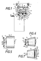
- FIG. 1 shows a textile machine 1 producing cross-wound bobbins, which has a multiplicity of work stations 2 at which cross-wound bobbins 3 are wound. Only one of the large number of workplaces is shown in a side view. Only the features contributing to the understanding of the invention are shown and explained in more detail.
- the package has reached its intended amount of yarn.
- the cross-wound bobbin 3 which is still held rotatably in the bobbin frame 4, has been lifted off its bobbin drive 5.
- the bobbin drive 5 consists of a winding roller which drives the cross-wound bobbin 3 by means of friction and which can be driven by a shaft 6 guided along the machine.
- the cross-wound bobbin 3 is lifted off the winding roller 5, for example, by a pneumatic lifting device 7 which engages the bobbin frame 4.
- the pneumatic lifting device 7 When the pneumatic lifting device 7 is actuated, the bobbin frame pivots about the pivot axis 8.
- the cross-wound bobbin moves on a circular path 9 and is lifted off the winding roller 5. In this state, the feeding of the yarn 10 is interrupted by a yarn delivery point, not shown here, for example a spinning point.
- a bobbin changing carriage 11 has been positioned at the winding unit 2 as a mobile service facility. It has a package changer and also carries a tube magazine 12 with a supply of empty tubes 13.
- the bobbin changing carriage is supported by guide rollers 14 and 15 on rails 16 and 17 on the machine.
- a thread suction device On the bobbin changing carriage 11 there is a thread suction device, designated overall by 18. It consists of a suction nozzle 19, as is known for example from DE-OS 36 02 574. This suction nozzle is used to suck in and pull off the thread end that has run onto the surface of the package.
- the suction nozzle 19 is pivotable about the pivot point 20, so that its suction opening 21 can be moved on a circular path 22 to the peripheral surface of the package 3.
- the suction opening 21 is already directed onto the peripheral surface of the cheese 3 and has sucked in the thread end 23 that has run there.
- the thread end 23 is being wound up to a thread reserve on the sleeve on the end face of the package.
- the cheese 3 is driven by an auxiliary drive 24.
- the auxiliary drive 24 rotates the cross-wound bobbin 3 in the direction of the arrow 26, the direction of rotation in which the thread is wound during winding, by means of a friction wheel which bears against the circumferential surface of the bobbin and rotates in the direction of arrow 25.
- the auxiliary drive can be delivered by means of a holder 27 about the pivot point 28 on a circular path 29 of the cheese 3.
- a thread guide element 30 of the embodiment according to the invention lies against the end face of the package 3 and guides the thread 23, which extends from the suction opening 21 over the end face 31 of the package 3.
- the thread guide element 30 is pressed against the end face 31 of the cheese 3 by an actuating element 32.
- the actuating element 32 is pivotally mounted in the pivot point 33 on the bobbin changing carriage 11 and becomes the Operation pivoted out of the rest position 32 'according to the movement path 34 in the direction against the thread guide element.
- the fully wound cross-wound bobbin is lifted out of the bobbin frame in a known manner, as described for example in DE-OS 36 02 574, and placed on a conveyor belt 35 for removal.
- An empty sleeve 13 is then removed from the sleeve magazine 12 by means of a sleeve feeder 36.
- the sleeve feeder 36 grips an empty sleeve 13 and, rotating along the circular arc 38 around the pivot point 39, brings it into the open coil frame 4.
- the sleeve is clamped in the coil frame and the sleeve feeder 36 swings back into its starting position.
- Fig. 2 shows the part of the bobbin frame 4 on which the thread guide element 30 is pivotally mounted.
- the cheese 3 consists of the package 44 and the sleeve 45, one end of which protrudes from the end face 31 of the cheese 3. This end is held by a sleeve plate 46 which is rotatably mounted in a bearing 47 in the holder arm 40 of the coil frame 4.
- the thread guide element 30 lies parallel to the holder arm 40 and thus parallel to the end face 31 of the cheese 4. It can be held in this position by a spring (not shown here) or by gravity.
- An embodiment of the thread guide element can be seen from FIGS. 3 and 4.
- the thread guide element has a flat contour and encompasses the sleeve on its circumference.
- Thread guide element 30 sleeve 45 by 180 degrees, reaching around by 90 degrees in the area of the thread course, thus thus an embodiment with a quarter segment, is also conceivable.
- the thread guide element 30 contains, in the area in which it comes to rest on the end face 31 in the area of the sleeve 45 of the package 3, a thread guide surface 48 which conforms to the end face 31 of the package.
- the thread catch notch 49 is located where the thread guide surface 48 comes to rest on the end face of the package. This thread catch notch 49 is cut in such a way that it catches the thread 23 running from the sleeve 45 to the suction nozzle 21 and on the end face 31 of the package 3 brings to the plant.
- this thread 23 is first wound up on the end of the sleeve 45 to form a thread reserve 50 before the thread end 23 emerging from the suction nozzle 21 is brought into contact with the end face 31 of the package 3 by means of the thread guide element 30. Since the thread end 23 drawn out of the suction opening 21 is no longer under tension, there is a risk that it will be flung loosely around the sleeve without a thread guide element.
- the thread guide element grips the slack thread 23 with its thread catch notch 49, as can be seen in FIG. 2, and first causes a further winding on the sleeve and a subsequent ironing of the thread end with the help of the thread guide surface 48 onto the end face 31 of the package 3.
- the thread guide element 30 with its thread guide surface 48 can be brought into contact with the end face 31 of the cheese 4, it has an angled tab 51 acting as a lever arm above the pivot point about the axis 43.
- This tab 51 is perpendicular to the base body of the thread guide element angled. If the actuating element 32 acts on the tab 51, as shown in FIG. 2 by means of the dashed arrow, the thread guide element 30 becomes its own Rest position pivoted into position 30 'and comes with its thread guide surface 48 on the end face 31 of the package 3 to the plant.
- the thread guide element can also be actuated by the pressure lever of the package changer.
- FIG. 5 shows a cylindrical cheese, as is also shown in FIG. 2.
- the thread guide surface 48 of the thread guide element 30, which is shown in accordance with the section shown in FIG. 3, has a course which is parallel to the end face 31 of the cheese in the contact surface.
- FIG. 6 and 7 each show a conical cross-wound bobbin 53 and 54, respectively.
- the end face 55 at the tip of the conical bobbin sleeve 56 is drawn in concavely, so that a correspondingly designed thread guide surface 48a of the thread guide element 30a comes to rest on the end face 55.
- the contour of the thread guide surface 48a is modeled on the end face contour 55. If the thread guide element 30a is pressed with its thread guide surface 48a in the direction of arrow 57 against the cross-wound bobbin rotating in the winding direction 58, the free thread end 23a is gripped by the thread catching notch 49a and brought to bear against the end face 55 of the cross-wound bobbin 53 and fixed there.
- a concave contour of the thread guide surface 48b of the thread guide element 30b comes to rest on this end face.
- the thread guide surface 48 of the thread guide element 30b is optimally adapted to the contour of the end face 60 of the conical cheese 54. If the thread guide element 30b is moved in the direction of movement 61 towards the end face 60 of the cheese 54, which moves in the winding direction 62, the thread 23b is gripped by the thread catch notch 49b, directed against the end face 60 and brought there to fix it, due to the Friction sticks to the thread layers on the face.
Landscapes
- Replacing, Conveying, And Pick-Finding For Filamentary Materials (AREA)
Description
- Die Erfindung betrifft eine Vorrichtung zum Bilden einer Fadenreserve auf Kreuzspulen an den Spulstellen einer Kreuzspulen herstellenden Textilmaschine mit einer Vielzahl von Arbeitsstellen und einer die Arbeitsstellen bedienenden fahrbaren Serviceeinrichtung, die zum Wechseln von Auflaufspulen eingerichtet ist, und die eine Antriebsvorrichtung für die in Wechselposition stehenden Kreuzspulen und eine Fadensaugvorrichtung zum Aufsuchen, Ansaugen und Abziehen des auf die Oberfläche der Kreuzspule aufgelaufenen Fadenendes aufweist, wobei dieses Fadenende mit Hilfe eines am Spulenrahmen befindlichen, auf die Kreuzspule zu und von der Kreuzspule wegbewegbaren Fadenleitelements auf dem Hülsenende zu einer Fadenreserve gewickelt wird.
- Es ist bekannt, bei Kreuzspulen zum besseren Auffinden des Fadenendes dieses Fadenende auf eines der Enden der Hülse als Fadenreserve oder Endreserve aufzuwickeln. Diese Fadenreserve erleichtert das Auffinden des Fadenendes und das Abziehen einer bestimmten Fadenlänge, um das Fadenende in die jeweils weiterverarbeitende Einrichtung einzuführen.
- Aus der DE-OS 36 02 574 ist ein Fadenleitelement bekannt, das am Spulenrahmen gelagert ist und auf die Kreuzspule zu und von der Kreuzspule wegbewegbar ist. Das Fadenleitelement ist um einen Schwenkpunkt am Spulenrahmen schwenkbar und kann beispielsweise unter dem Einfluß einer Feder in der Ruhelage gehalten werden. Soll eine Endreserve gewickelt werden, drückt ein Schalthebel das Fadenleitelement mit seiner Fadenleitkontur in die Nähe des Zwickels, der von dem Garnwickel und der Spulenhülse gebildet wird. Dabei wird der an der Stirnseite der Kreuzspule zur Fadensaugvorrichtung verlaufende Faden von der Fadenleitkontur erfaßt und wickelt sich auf die Hülse. Solange der Faden zwischen Hülse und Fadensaugvorrichtung aufgrund der anliegenden Saugströmung noch straff gespannt ist, wickelt sich der Faden auch in festen Windungen auf die Hülse.
- Sobald das Fadenende aber die Fadensaugvorrichtung verläßt, wird der Faden schlaff. Die Fadenleitkontur kann zwar das Fadenende noch zur Hülse leiten, die restlichen Windungen, insbesondere die letzte Windung, bleiben aufgrund der fehlenden Zugwirkung auf den Faden schlaff.
- Die letzten Fadenwicklungen auf der Hülse können dadurch leicht abfallen oder abgezogen werden. Insbesondere beim automatischen Transport von Kreuzspulen kann sich das Fadenende weiter lösen und sich an Transportmitteln verhaken. Die Folge ist, daß Schleppfäden entstehen, die Reserve ganz abgezogen wird oder die Kreuzspule hängenbleibt und das Transportsystem blockiert.
- Der Erfindung liegt deshalb die Aufgabe zugrunde, die aufgezeigten Nachteile zu vermeiden und eine Fadenreserve zu bilden, die optimal gegen Lösen gesichert ist.
- Gemäß der Erfindung wird diese Aufgabe dadurch gelöst, daß das Fadenleitelement in Umfangsrichtung der Hülse einen Sektor von mindestens 90 Grad aufweist, daß das Fadenleitelement an seiner Fadenleitfläche, die an der Stirnseite der Kreuzspule anlegbar ist, eine unmittelbar der Stirnseite der Kreuzspule benachbarte Fadenfangkerbe aufweist und daß ein Betätigungselement zur Betätigung des Fadenleitelements vorgesehen ist.
- Die Fadenleitvorrichtung ist am Spulenrahmen angebracht, um den aufzuwickelnden Faden dicht an die Stirnseite der Kreuzspule zu führen. Während im normalen Spulbetrieb die Fadenleitvorrichtung am Spulenrahmen anliegt, wird sie zum Wickeln der Fadenreserve so gegen die Stirnseite der Spule verschwenkt, daß sie dort zur Anlage kommt. Das Fadenleitelement hat dort, wo der Faden beim Aufwickeln auf die Hülse aufläuft, eine Fadenfangkerbe, mit der der Faden beim Aufwickeln an die Stirnseite der Spule geführt wird. Während der Bildung der Fadenreserve wird der Faden zunächst aus der Saugdüse unter Spannung herausgezogen und in mehreren Wicklungen auf die Hülse aufgewickelt. Durch das Fadenleitelement mit seiner Fadenleitfläche wird der Faden so geführt, daß er stirnseitig am Garnwickel auf der Hülse abgelegt wird. Bei diesem Aufwickelvorgang gerät der Faden in die Fadenfangkerbe. Wenn das Fadenende nach Verlassen der Saugdüse ohne Spannung ist und deshalb nicht mehr straff gehalten wird, wird es weiter durch die Kerbe geführt. Dadurch wird es vollkommen aufgewickelt. Das Fadenende wird durch die Anlage der stirnseitigen Fadenleitfläche des Fadenleitelements an der Stirnseite des Garnwickels eingebügelt und ist dadurch infolge der Reibung des Fadens an der Stirnseite für den Transport gut gesichert.
- In einer Weiterbildung der Erfindung ist das Fadenleitelement der jeweiligen Kontur der Stirnseite der Spule angepaßt, an der es zur Anlage bringbar ist. Diese Anpassung ist besonders wichtig bei kegelförmigen Kreuzspulen. Da deren Stirnseiten in der Regel nicht plan sind, ist es von Vorteil, wenn die Fadenleitfläche des Fadenleitelements der Stirnseite der Spule angepaßt ist, damit zwischen dem Fadenleitelement und der Stirnseite der Spule kein Freiraum oder Spalt entsteht, in welchem der Faden sich frei und ohne Führung bewegen könnte. Je nachdem, ob die Fadenreserve an der oberen Stirnseite der Spule oder an der unteren Stirnseite der Spule gewünscht wird, hat das Fadenleitelement eine konvexe beziehungsweise eine konkav geformte Kontur.
- In einer weiteren Ausgestaltung der Erfindung ist die Fadenfangkerbe am Fadenleitelement dort angeordnet, wo das Fadenleitelement im Bereich der Hülse zur Anlage kommt. Eine so angeordnete Fadenfangkerbe führt den Faden sicher in den Bereich der Hülse, so daß er auf dieser zur Fadenreserve aufgewickelt werden kann und auch das Fadenende möglichst im Bereich der Hülse auf der Stirnseite der Kreuzspule zu liegen kommt. Dadurch ist es bei der Weiterbehandlung der Kreuzspule leichter aufzufinden.
- Anhand eines schematisch dargestellten Ausführungsbeispiels wird die Erfindung näher erläutert.
- Es zeigen:
- Fig. 1
- eine Spulstelle an einer Kreuzspulen herstellenden Textilmaschine mit der erfindungsgemäßen Vorrichtung zum Bilden einer Fadenreserve,
- Fig. 2
- die erfindungsgemäße Vorrichtung als Einzelheit,
- Fig. 3
- das Fadenleitelement der Vorrichtung als Einzelheit in einer Frontansicht und
- Fig. 4
- in einer Seitenansicht,
- Fig. 5
- eine zylindrische Kreuzspule mit der zugehörigen Fadenleitfläche eines Fadenleitelements,
- Fig. 6
- eine kegelförmige Kreuzspule mit der zugehörigen Fadenleitfläche eines Fadenleitelements für den Kopfbereich und
- Fig. 7
- für den Fußbereich.
- Das Ausführungsbeispiel nach Fig. 1 zeigt eine Kreuzspulen herstellende Textilmaschine 1, die eine Vielzahl von Arbeitsstellen 2 aufweist, an denen Kreuzspulen 3 gewickelt werden. Von der Vielzahl der Arbeitsstellen ist hier nur eine in Seitenansicht dargestellt. Es sind nur die zum Verständnis der Erfindung beitragenden Merkmale dargestellt und näher erläutert.
- Im vorliegenden Ausführungsbeispiel hat die Kreuzspule ihre vorgesehene Garnmenge erreicht. Aus diesem Grund ist die Kreuzspule 3, die noch im Spulenrahmen 4 drehbar gehalten wird, von ihrem Spulenantrieb 5 abgehoben worden. Der Spulenantrieb 5 besteht aus einer die Kreuzspule 3 mittels Friktion antreibende Wickelwalze, die durch eine längs der Maschine geführte Welle 6 antreibbar ist. Das Abheben der Kreuzspule 3 von der Wickelwalze 5 erfolgt beispielsweise durch eine pneumatische Hebevorrichtung 7, die an dem Spulenrahmen 4 angreift. Bei Betätigung der pneumatischen Hebevorrichtung 7 schwenkt der Spulenrahmen um die Schwenkachse 8. Dabei bewegt sich die Kreuzspule auf einer Kreisbahn 9 und wird von der Wickelwalze 5 abgehoben. In diesem Zustand ist die Zuführung des Garns 10 von einer hier nicht dargestellten Garnlieferstelle, beispielsweise einer Spinnstelle, unterbrochen.
- An der Spulstelle 2 hat sich als fahrbare Serviceeinrichtung ein Spulenwechselwagen 11 positioniert. Er hat eine Kreuzspulenwechseleinrichtung und führt außerdem ein Hülsenmagazin 12 mit einem Vorrat leerer Hülsen 13 mit sich.
- Der Spulenwechselwagen stützt sich mit Führungsrollen 14 und 15 auf Fahrschienen 16 und 17 an der Maschine ab.
- Auf dem Spulenwechselwagen 11 befindet sich eine insgesamt mit 18 bezeichnete Fadensaugvorrichtung. Sie besteht aus einer Saugdüse 19, wie sie beispielsweise aus der DE-OS 36 02 574 bekannt ist. Diese Saugdüse dient zum Ansaugen und Abziehen des auf der Oberfläche der Kreuzspule aufgelaufenen Fadenendes. Die Saugdüse 19 ist um den Schwenkpunkt 20 schwenkbar, so daß sich ihre Ansaugöffnung 21 auf einer Kreisbahn 22 bewegend der Umfangsfläche der Kreuzspule 3 zustellen läßt. Im vorliegenden Ausführungsbeispiel nach Fig. 1 ist die Ansaugöffnung 21 bereits auf die Umfangsfläche der Kreuzspule 3 gerichtet und hat das dort aufgelaufene Fadenende 23 angesaugt.
- Das Fadenende 23 wird gerade zu einer Fadenreserve auf der Hülse an der Stirnseite der Kreuzspule aufgewickelt. Zur Bildung der Fadenreserve wird die Kreuzspule 3 mit einem Hilfsantrieb 24 angetrieben. Der Hilfsantrieb 24 dreht mittels eines an der Umfangsfläche der Kreuzspule anliegenden Reibrads, das sich in Pfeilrichtung 25 dreht, die Kreuzspule 3 in Pfeilrichtung 26, der Drehrichtung, in welcher der Faden während des Spulen aufgewickelt wird. Der Hilfsantrieb ist mittels einer Halterung 27 um den Schwenkpunkt 28 auf einer Kreisbahn 29 der Kreuzspule 3 zustellbar.
- Während des Drehens der Kreuzspule ist die erfindungsgemäße Vorrichtung zum Bilden der Fadenreserve in Tätigkeit. Ein Fadenleitelement 30 der erfindungsgemäßen Ausführung liegt an der Stirnseite der Kreuzspule 3 an und führt den Faden 23, der sich von der Ansaugöffnung 21 über die Stirnseite 31 der Kreuzspule 3 zieht. Das Fadenleitelement 30 wird über ein Betätigungselement 32 gegen die Stirnseite 31 der Kreuzspule 3 gedrückt. Das Betätigungselement 32 ist im Schwenkpunkt 33 am Spulenwechselwagen 11 schwenkbar gelagert und wird zur Betätigung aus der Ruhelage 32' heraus entsprechend der Bewegungsbahn 34 in Richtung gegen das Fadenleitelement geschwenkt.
- Nach Bildung der Fadenreserve wird die fertiggewickelte Kreuzspule in bekannter Weise, wie beispielsweise in der DE-OS 36 02 574 beschrieben, aus dem Spulenrahmen gehoben und auf ein Transportband 35 zum Abtransport abgelegt. Danach wird mittels eines Hülsenzubringers 36 eine leere Hülse 13 aus dem Hülsenmagazin 12 entnommen. Mit seiner Hülsengreifvorrichtung 37 ergreift der Hülsenzubringer 36 eine leere Hülse 13 und bringt sie, längs des Kreisbogens 38 um den Schwenkpunkt 39 sich drehend, in den geöffneten Spulenrahmen 4. Die Hülse wird in den Spulenrahmen eingespannt und der Hülsenzubringer 36 schwenkt in seine Ausgangslage zurück.
- Fig. 2 zeigt den Teil des Spulenrahmens 4, an der das Fadenleitelement 30 schwenkbar gelagert ist. Auf einem der Halterarme des Spulenrahmens 4, auf dem Halterarm 40, befinden sich zwei Angeln 41 und 42 (Fig. 3), durch welche eine Achse 43 verläuft, an der das Fadenleitelement 30 schwenkbar befestigt ist.
- Die Kreuzspule 3 besteht aus dem Garnkörper 44 und der Hülse 45, von der ein Ende aus der Stirnseite 31 der Kreuzspule 3 herausragt. Dieses Ende wird von einem Hülsenteller 46 gehalten, der in einem Lager 47 drehbar in dem Halterarm 40 des Spulenrahmens 4 gelagert ist. Das Fadenleitelement 30 liegt in Ruhestellung parallel zum Halterarm 40 und damit parallel zur Stirnseite 31 der Kreuzspule 4. Es kann durch eine hier nicht dargestellte Feder oder durch die Schwerkraft in dieser Stellung gehalten werden. Aus den Fig. 3 und 4 ist eine Ausführungsform des Fadenleitelements ersichtlich. Das Fadenleitelement hat eine flache Kontur und umgreift die Hülse auf ihrem Umfang. Im vorliegenden Fall umgreift das Fadenleitelement 30 die Hülse 45 um 180 Grad, ein Umgreifen um etwa 90 Grad im Bereich des Fadenverlaufs, somit also eine Ausführungsform mit einem Viertelsegment, ist ebenfalls denkbar. Das Fadenleitelement 30 enthält in dem Bereich, in dem es an der Stirnseite 31 im Bereich der Hülse 45 der Kreuzspule 3 zur Anlage kommt, eine Fadenleitfläche 48, die sich der Stirnseite 31 der Kreuzspule anschmiegt. Dort, wo die Fadenleitfläche 48 an die Stirnseite der Kreuzspule zur Anlage kommt, befindet sich die Fadenfangkerbe 49. Diese Fadenfangkerbe 49 ist so geschnitten, daß sie den von der Hülse 45 zur Saugdüse 21 verlaufenden Faden 23 fängt und an der Stirnseite 31 der Kreuzspule 3 zur Anlage bringt.
- Wie aus der Fig. 2 ersichtlich, wird dieser Faden 23 zunächst auf dem Ende der Hülse 45 zu einer Fadenreserve 50 aufgewickelt, bevor das aus der Saugdüse 21 heraustretende Fadenende 23 an der Stirnseite 31 der Kreuzspule 3 mittels des Fadenleitelements 30 zur Anlage gebracht wird. Da das aus der Ansaugöffnung 21 herausgezogene Fadenende 23 nicht mehr unter Spannung steht, besteht die Gefahr, daß es ohne Fadenleitelement lose um die Hülse herumgeschleudert wird. Das Fadenleitelement ergreift mit seiner Fadenfangkerbe 49 den schlaffen Faden 23, wie aus der Fig. 2 ersichtlich, und bewirkt zunächst ein weiteres Aufwickeln auf der Hülse und ein anschließendes Anbügeln des Fadenendes mit Hilfe der Fadenleitfläche 48 auf die Stirnseite 31 der Kreuzspule 3.
- Damit das Fadenleitelement 30 mit seiner Fadenleitfläche 48 an der Stirnseite 31 der Kreuzspule 4 zur Anlage gebracht werden kann, besitzt es einen oberhalb des Drehpunkts um die Achse 43 eine abgewinkelte, als Hebelarm wirkende Lasche 51. Diese Lasche 51 ist rechtwinklig von dem Grundkörper des Fadenleitelements abgewinkelt. Wirkt das Betätigungselement 32, wie in Fig. 2 mittels des gestrichelten Pfeils dargestellt, auf die Lasche 51, so wird das Fadenleitelement 30 aus seiner Ruheposition in die Position 30' geschwenkt und kommt mit seiner Fadenleitfläche 48 an der Stirnseite 31 der Kreuzspule 3 zur Anlage. Die Betätigung des Fadenleitelements kann auch alternativ durch den Andrückhebel des Kreuzspulenwechslers ausgeübt werden.
- In den Fig. 5, 6 und 7 sind mögliche Ausbildungsformen der Fadenleitfläche 48 der Fadenleitelemente passend zu den unterschiedlichen möglichen Stirnseitenausbildungen der Kreuzspulen dargestellt.
- Fig. 5 zeigt eine zylindrische Kreuzspule, wie sie auch in der Fig. 2 dargestellt ist. Die Fadenleitfläche 48 des Fadenleitelements 30, das entsprechend dem in Fig. 3 angegebenen Schnitt dargestellt ist, hat einen Verlauf, der in der Anlagefläche parallel zur Stirnseite 31 der Kreuzspule liegt. Wenn sich die Kreuzspule 4 in Wickelrichtung 26 dreht, wird das Fadenleitelement in Pfeilrichtung 52 gegen die Stirnseite 31 der Kreuzspule 3 gedrückt und fängt den Faden 23 mit der Fadenfangkerbe 49 und drückt ihn gegen die Stirnseite 31 der Kreuzspule.
- Die Fig. 6 und 7 zeigen jeweils eine konische Kreuzspule 53 beziehungsweise 54. Die Stirnseite 55 an der Spitze der kegelförmigen Spulenhülse 56 ist konkav eingezogen, so daß eine entsprechend ausgebildete Fadenleitfläche 48a des Fadenleitelements 30a an der Stirnseite 55 zur Anlage kommt. Die Kontur der Fadenleitfläche 48a ist der Stirnseitenkontur 55 nachgebildet. Wird das Fadenleitelement 30a mit seiner Fadenleitfläche 48a in Pfeilrichtung 57 gegen die sich in Wickelrichtung 58 drehende Kreuzspule gedrückt, wird das freie Fadenende 23a von der Fadenfangkerbe 49a erfaßt und gegen die Stirnseite 55 der Kreuzspule 53 zur Anlage gebracht und dort fixiert.
- Soll die Fadenreserve an der Basisstirnseite 60 der konischen Kreuzspule 54 auf das dicke Ende der konischen Hülse 59 gewickelt werden, so kommt auf dieser Stirnseite eine konkav geformte Kontur der Fadenleitfläche 48b des Fadenleitelements 30b zur Anlage. Mit seiner konkav ausgebildeten Kontur ist die Fadenleitfläche 48 des Fadenleitelements 30b der Kontur der Stirnseite 60 der konischen Kreuzspule 54 optimal angepaßt. Wird das Fadenleitelement 30b in Bewegungsrichtung 61 auf die Stirnseite 60 der Kreuzspule 54 zubewegt, welche sich in Wickelrichtung 62 bewegt, so wird der Faden 23b von der Fadenfangkerbe 49b erfaßt, gegen die Stirnseite 60 gelenkt und dort fixierend zur Anlage gebracht, wobei er aufgrund der Reibung an den Fadenlagen der Stirnseite haftenbleibt.
Claims (3)
- Vorrichtung zum Bilden einer Fadenreserve auf Kreuzspulen (3, 53, 54) an den Spulstellen einer Kreuzspulen (3, 53, 54) herstellenden Textilmaschine (1) mit einer Vielzahl von Arbeitsstellen (2) und einer die Arbeitsstellen bedienenden fahrbaren Serviceeinrichtung (11), die zum Wechseln von Auflaufspulen eingerichtet ist, und die eine Antriebsvorrichtung (24) für die in Wechselposition stehenden Kreuzspulen (3, 53, 54) und eine Fadensaugvorrichtung (18) zum Aufsuchen, Ansaugen und Abziehen des auf die Oberfläche der Kreuzspule aufgelaufenen Fadenendes aufweist, wobei dieses Fadenende mit Hilfe eines am Spulenrahmen befindlichen, auf die Kreuzspule zu und von der Kreuzspule wegbewegbaren Fadenleitelements (30, 30a, 30b) auf dem Hülsenende der Kreuzspule zu einer Fadenreserve gewickelt wird und wobei ein Betätigungselement (32) zur Betätigung des Fadenleitelements (30, 30a, 30b) vorgesehen ist,
dadurch gekennzeichnet,
daß das Fadenleitelement (30, 30a, 30b) in Umfangsrichtung der Hülse (45, 56, 59) einen Sektor von mindestens 90 Grad aufweist, daß das Fadenleitelement (30, 30a, 30b) an seiner Fadenleitfläche (48, 48a, 48b), die an der Stirnseite (31, 55, 60) der Kreuzspule anlegbar ist, eine unmittelbar der Stirnseite (31, 55, 60) der Kreuzspule (3, 53, 54) benachbarte Fadenfangkerbe (49, 49a, 49b) aufweist. - Vorrichtung nach Anspruch 1, dadurch gekennzeichnet, daß das Fadenleitelement (30, 30a, 30b) der jeweiligen Kontur der Stirnseite (31, 55, 60) der Spule (3, 53, 54) angepaßt ist, an der es zur Anlage bringbar ist.
- Vorrichtung nach Anspruch 1 oder 2, dadurch gekennzeichnet, daß die Fadenfangkerbe (49, 49a, 49b) am Fadenleitelement (30, 30a, 30b) dort angeordnet ist, wo das Fadenleitelement im Bereich der Hülse (45, 56, 59) zur Anlage kommt.
Applications Claiming Priority (2)
| Application Number | Priority Date | Filing Date | Title |
|---|---|---|---|
| DE4202962 | 1992-02-01 | ||
| DE4202962A DE4202962A1 (de) | 1992-02-01 | 1992-02-01 | Vorrichtung zum bilden einer fadenreserve |
Publications (2)
| Publication Number | Publication Date |
|---|---|
| EP0554666A1 EP0554666A1 (de) | 1993-08-11 |
| EP0554666B1 true EP0554666B1 (de) | 1995-05-03 |
Family
ID=6450820
Family Applications (1)
| Application Number | Title | Priority Date | Filing Date |
|---|---|---|---|
| EP93100243A Expired - Lifetime EP0554666B1 (de) | 1992-02-01 | 1993-01-09 | Vorrichtung zum Bilden einer Fadenreserve |
Country Status (3)
| Country | Link |
|---|---|
| US (1) | US5362007A (de) |
| EP (1) | EP0554666B1 (de) |
| DE (2) | DE4202962A1 (de) |
Families Citing this family (4)
| Publication number | Priority date | Publication date | Assignee | Title |
|---|---|---|---|---|
| DE4445269A1 (de) * | 1994-12-19 | 1996-06-20 | Schlafhorst & Co W | Verfahren und Vorrichtung zum Festlegen des Fadenendes einer Fadenreserve |
| US5549229A (en) * | 1995-02-06 | 1996-08-27 | Chrysler Corporation | Luggage rack |
| ID24874A (id) * | 1997-08-22 | 2000-08-31 | Corning Inc | Metoda dan peralatan untuk menggulung serat pada suatu gelendong |
| JP3698873B2 (ja) * | 1997-10-03 | 2005-09-21 | ナブテスコ株式会社 | 糸条パッケージの形成方法および形成装置 |
Family Cites Families (7)
| Publication number | Priority date | Publication date | Assignee | Title |
|---|---|---|---|---|
| NL101702C (de) * | 1958-06-10 | |||
| DE3336865A1 (de) * | 1982-10-13 | 1984-04-19 | Barmag Barmer Maschinenfabrik Ag, 5630 Remscheid | Aufspulvorrichtung |
| JPS60112569A (ja) * | 1983-11-18 | 1985-06-19 | Toray Ind Inc | 糸条パツケ−ジのテ−ル形成方法 |
| DE3602574C2 (de) * | 1986-01-29 | 1997-06-12 | Schlafhorst & Co W | Kreuzspulen herstellende Maschine mit Vorrichtung zur Bildung einer Fadenendreserve auf einer fertig gewickelten Spule |
| JPH02209370A (ja) * | 1989-02-08 | 1990-08-20 | Murata Mach Ltd | バンチ巻方法 |
| JPH02239063A (ja) * | 1989-03-13 | 1990-09-21 | Murata Mach Ltd | 自動ワインダー |
| JP2751499B2 (ja) * | 1989-12-18 | 1998-05-18 | 村田機械株式会社 | テールエンドの糸処理方法 |
-
1992
- 1992-02-01 DE DE4202962A patent/DE4202962A1/de not_active Withdrawn
-
1993
- 1993-01-09 DE DE59300168T patent/DE59300168D1/de not_active Expired - Fee Related
- 1993-01-09 EP EP93100243A patent/EP0554666B1/de not_active Expired - Lifetime
- 1993-02-01 US US08/011,964 patent/US5362007A/en not_active Expired - Lifetime
Also Published As
| Publication number | Publication date |
|---|---|
| EP0554666A1 (de) | 1993-08-11 |
| DE59300168D1 (de) | 1995-06-08 |
| DE4202962A1 (de) | 1993-08-05 |
| US5362007A (en) | 1994-11-08 |
Similar Documents
| Publication | Publication Date | Title |
|---|---|---|
| DE3426655C2 (de) | ||
| CH623082A5 (de) | ||
| DE3602574C2 (de) | Kreuzspulen herstellende Maschine mit Vorrichtung zur Bildung einer Fadenendreserve auf einer fertig gewickelten Spule | |
| DE2541761A1 (de) | Verfahren und vorrichtung zur bildung einer anknuepf-reservewicklung auf spulen an textilmaschinen | |
| DE3922799C2 (de) | Vorrichtung zum Austausch von Spulen bzw. Hülsen | |
| DE3918788C2 (de) | ||
| DE2312609A1 (de) | Verfahren und vorrichtung zum auswechseln einer vollen kreuzspule gegen eine leere huelse | |
| DE3817493A1 (de) | Spinnmaschine mit einer vielzahl von spinnaggregaten zum erzeugen von als vorlagespulen fuer ein zwirnen dienenden spulen | |
| EP2279976B1 (de) | Verfahren zum Betreiben von Arbeitsstellen einer Kreuzspulen herstellenden Textilmaschine | |
| DE3543572C2 (de) | Vorrichtung zum Abwickeln und anschließendem Wiederaufwickeln eines Fadens anläßlich der Behebung eines Fadenbruches | |
| DE69735326T2 (de) | Wickelmaschine für einen elastischen Faden | |
| DE19836702A1 (de) | Kreuzspulen herstellende Textilmaschine | |
| EP0994821B1 (de) | Aufspulmaschine | |
| DE3337343C2 (de) | ||
| EP0554666B1 (de) | Vorrichtung zum Bilden einer Fadenreserve | |
| EP0286893A1 (de) | Verfahren zum Anlegen eines mit konstanter geschwindigkeit angelieferten Fadens an eine Spulhülse | |
| DE4226364C2 (de) | Verfahren und Vorrichtung zum Spulenwechsel | |
| DE10150590A1 (de) | Arbeitsstelle einer Kreuzspulen herstellenden Textilmaschine | |
| DE102004051880A1 (de) | Vorrichtung zur Optimierung des Fadenabzugs an einer Spulstelle eines Kreuzspulautomaten | |
| DE19524946B4 (de) | Kreuzspulen herstellende Textilmaschine | |
| DE2443616C3 (de) | Automatische an Ringspinnmaschinen verfahrbare Einfädelvorrichtung | |
| DE2330961C3 (de) | Vorrichtung zur Bildung einer Fadenreserve auf einer Aufwickelspule mit wilder Wicklung an schnellaufenden Spulmaschinen | |
| CH677919A5 (de) | ||
| DE102007050791A1 (de) | Aufspulmaschine | |
| DE3146263A1 (de) | "verfahren und spulmaschine zum aufwickeln eines mit hoher geschwindigkeit kontinuierlich angelieferten fadens auf einer spule" |
Legal Events
| Date | Code | Title | Description |
|---|---|---|---|
| PUAI | Public reference made under article 153(3) epc to a published international application that has entered the european phase |
Free format text: ORIGINAL CODE: 0009012 |
|
| AK | Designated contracting states |
Kind code of ref document: A1 Designated state(s): CH DE IT LI |
|
| 17P | Request for examination filed |
Effective date: 19931008 |
|
| 17Q | First examination report despatched |
Effective date: 19940706 |
|
| ITF | It: translation for a ep patent filed | ||
| GRAA | (expected) grant |
Free format text: ORIGINAL CODE: 0009210 |
|
| AK | Designated contracting states |
Kind code of ref document: B1 Designated state(s): CH DE IT LI |
|
| REF | Corresponds to: |
Ref document number: 59300168 Country of ref document: DE Date of ref document: 19950608 |
|
| PLBE | No opposition filed within time limit |
Free format text: ORIGINAL CODE: 0009261 |
|
| STAA | Information on the status of an ep patent application or granted ep patent |
Free format text: STATUS: NO OPPOSITION FILED WITHIN TIME LIMIT |
|
| 26N | No opposition filed | ||
| PGFP | Annual fee paid to national office [announced via postgrant information from national office to epo] |
Ref country code: CH Payment date: 19990210 Year of fee payment: 7 |
|
| PG25 | Lapsed in a contracting state [announced via postgrant information from national office to epo] |
Ref country code: LI Free format text: LAPSE BECAUSE OF NON-PAYMENT OF DUE FEES Effective date: 20000131 Ref country code: CH Free format text: LAPSE BECAUSE OF NON-PAYMENT OF DUE FEES Effective date: 20000131 |
|
| REG | Reference to a national code |
Ref country code: CH Ref legal event code: PL |
|
| PGFP | Annual fee paid to national office [announced via postgrant information from national office to epo] |
Ref country code: IT Payment date: 20080123 Year of fee payment: 16 Ref country code: DE Payment date: 20080218 Year of fee payment: 16 |
|
| PG25 | Lapsed in a contracting state [announced via postgrant information from national office to epo] |
Ref country code: DE Free format text: LAPSE BECAUSE OF NON-PAYMENT OF DUE FEES Effective date: 20090801 |
|
| PG25 | Lapsed in a contracting state [announced via postgrant information from national office to epo] |
Ref country code: IT Free format text: LAPSE BECAUSE OF NON-PAYMENT OF DUE FEES Effective date: 20090109 |