EP0555949A1 - Dispositif de fixation pour connecteur pour appareils des applications mobiles - Google Patents
Dispositif de fixation pour connecteur pour appareils des applications mobiles Download PDFInfo
- Publication number
- EP0555949A1 EP0555949A1 EP93250048A EP93250048A EP0555949A1 EP 0555949 A1 EP0555949 A1 EP 0555949A1 EP 93250048 A EP93250048 A EP 93250048A EP 93250048 A EP93250048 A EP 93250048A EP 0555949 A1 EP0555949 A1 EP 0555949A1
- Authority
- EP
- European Patent Office
- Prior art keywords
- fastening device
- opening
- struts
- receptacle
- openings
- Prior art date
- Legal status (The legal status is an assumption and is not a legal conclusion. Google has not performed a legal analysis and makes no representation as to the accuracy of the status listed.)
- Withdrawn
Links
Images

Classifications
-
- H—ELECTRICITY
- H01—ELECTRIC ELEMENTS
- H01R—ELECTRICALLY-CONDUCTIVE CONNECTIONS; STRUCTURAL ASSOCIATIONS OF A PLURALITY OF MUTUALLY-INSULATED ELECTRICAL CONNECTING ELEMENTS; COUPLING DEVICES; CURRENT COLLECTORS
- H01R13/00—Details of coupling devices of the kinds covered by groups H01R12/70 or H01R24/00 - H01R33/00
- H01R13/62—Means for facilitating engagement or disengagement of coupling parts or for holding them in engagement
- H01R13/629—Additional means for facilitating engagement or disengagement of coupling parts, e.g. aligning or guiding means, levers, gas pressure electrical locking indicators, manufacturing tolerances
-
- H—ELECTRICITY
- H01—ELECTRIC ELEMENTS
- H01R—ELECTRICALLY-CONDUCTIVE CONNECTIONS; STRUCTURAL ASSOCIATIONS OF A PLURALITY OF MUTUALLY-INSULATED ELECTRICAL CONNECTING ELEMENTS; COUPLING DEVICES; CURRENT COLLECTORS
- H01R2201/00—Connectors or connections adapted for particular applications
- H01R2201/02—Connectors or connections adapted for particular applications for antennas
Definitions
- the invention relates to a fastening device for a connector for devices for mobile use according to the preamble of the main claim.
- EP 88 73 0261 describes an antenna connector attachment for so-called quick-out car radios, in which a clip is connected to the connector of the antenna connector device, the clip having a center plate and spring struts bent away therefrom. The struts are bent outwards at their end and have an outward bias.
- the housing part to which the plug is to be fastened is provided with a round opening and, for mounting the plug, the struts encompassing it are compressed against the pretension and passed through the hole in such a way that the tabs on the surface of the housing lie on.
- a locking ring is provided which is inserted from the insertion side of the socket into the opening for the plug in the housing part and has snap lugs which engage under the housing part.
- the retaining ring is provided with a continuous flange or with projections that press on the bent ends and thus fix the struts.
- the invention is therefore based on the object to provide a fastening device for a plug connection for devices of mobile use, which holds the plug or the socket securely even over a long period and frequent use and in which, even with frequent plugging or unplugging of the plug connection, a good tolerance compensation between Plug and socket is given.
- the spring struts each have a barb at their ends, which preferably merges into a constriction to which spurs connect, and that openings are provided in the housing around the opening, the longitudinal axes of which are at a predetermined angle to that seen in cross section Longitudinal axis of the barb is, by twisting the struts and barbs slightly, the barbs can slide through the openings so that the constrictions are therein, the spurs preventing the struts from sliding through.
- the snap-back barbs form a lock in the openings and hold the antenna plug or the like in place, and on the basis of this definition a material for the clip can be selected which is not as elastic as steel, as a result of which no rust can occur.
- bracket In one and the same functional element, i.e. the bracket, can be separated between the holding function of the antenna plug in the housing wall and the function of tolerance compensation between the antenna plug and socket under quick-out pairing conditions, whereby there is the possibility of a separate optimization of both functions.
- no locking ring is necessary for the fastening device.
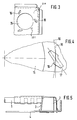
- FIG. 5 shows a connector 2 connected to an antenna cable 1, which is held elastically by means of a clip 3 in the housing 4, which is designed as a slide-in housing.
- the plug and the socket, not shown, are designed as a generally known coaxial connector, which need not be explained in more detail.
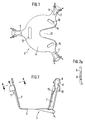
- a clip 3 is shown, which is provided for fastening the antenna plug 2 in the slide-in housing 4 of the car radio or a receptacle 20 provided in association with the housing.
- the clamp 3 has a plurality of struts 5 which are formed on a center plate 6.
- the struts are bent at an angle that is less than 90 °, ie an obtuse angle is provided between the center plate 6 and struts 5.
- a bead 7 is formed over part of its length, which increases the strength.
- barbs 8 are formed, which merge into a constriction 9 in the direction of the center plate 6, and the constrictions 9 are adjoined by a region of the struts in which spurs 10, 11 are formed, which are formed at an angle are bent outwards, one 11 of the two spurs tapering off at an angle.
- 2a which shows a section through the constriction 9 of the spring strut 5, it can be seen that the barbs 8 have radii on both hook ends, the curvatures of which are directed in opposite directions to one another.
- the barbs 8 are slightly twisted to the level of the struts 5, but they can lie exactly in this plane.
- center plate 6 there are longitudinal slots 12 which are used for connection to the antenna connector, with projections formed on the connector sleeve being inserted through the longitudinal slots 12 and being bent over.
- an arcuate incision 13 is provided in the center plate 6, the edges 14 of which are bent slightly outwards. This incision 13 is used to adapt the center plate 6 to the end of the sleeve of the plug receiving the coaxial cable.
- Figs. 3 and 4 are the openings and openings in a receptacle 20, e.g. the plug-in housing rear wall for the car radio.
- a circular opening 15 is shown, which is surrounded by three slot-like openings 16.
- the openings 16 serve to receive the ends of the spring struts 5 of the clamp 3.
- the openings 16, as can be seen better from FIG. 4, are arranged in such a way that their longitudinal axis 17 lies at an angle to the tangent 18 of a pitch circle 19, which is concentric is arranged to the circular opening 15 and goes through the center of the opening.
- the inside width of the opening 16 corresponds to the constriction 9
- in the direction of the longitudinal axis 17 corresponds to the greatest width of the barb 8 of the struts 5
- the thickness of the material of the plug-in housing rear wall corresponds to the length of the constriction.
- a centering opening 21 is provided in addition to the opening 15.
- the clip is preferably in the openings or openings by means of an auxiliary tool (Fig. 6) assembled.
- the clamp 3 is inserted into a sleeve 22 with longitudinal grooves 24 of the auxiliary tool, whereby the struts 5 are compressed.
- the ends of the barbs 8 are positioned over the openings 16, a centering pin 23 of the auxiliary tool engaging in the centering opening and the longitudinal axis of the spring struts 5 being at right angles to the tangent 18 of the pitch circle 19 of the openings 16.
- the spring struts are captive because they are positively locked in the receptacle 20 and are able to absorb both thrust and torsional movements in the plane described by the rear wall of the housing and also perpendicular to the latter.
- the clip is made of a soft material, such as brass or bronze.
- the insertion process can be carried out automatically with a corresponding robot or similar machine or with a hand tool according to FIG. 6 or also by hand.
- the breakthroughs i.e. their longitudinal axes in the rest state of the clip lie at a predetermined angle to the long axis of the barbs seen in cross section and that when inserted, the barbs are twisted so that their long axes match the longitudinal axes of the openings.
Landscapes
- Details Of Connecting Devices For Male And Female Coupling (AREA)
Applications Claiming Priority (2)
| Application Number | Priority Date | Filing Date | Title |
|---|---|---|---|
| DE9202102U DE9202102U1 (de) | 1992-02-14 | 1992-02-14 | Steckverbindung mit Befestigungsvorrichtung für Geräte des mobilen Einsatzes |
| DE9202102U | 1992-02-14 |
Publications (1)
| Publication Number | Publication Date |
|---|---|
| EP0555949A1 true EP0555949A1 (fr) | 1993-08-18 |
Family
ID=6876279
Family Applications (1)
| Application Number | Title | Priority Date | Filing Date |
|---|---|---|---|
| EP93250048A Withdrawn EP0555949A1 (fr) | 1992-02-14 | 1993-02-15 | Dispositif de fixation pour connecteur pour appareils des applications mobiles |
Country Status (2)
| Country | Link |
|---|---|
| EP (1) | EP0555949A1 (fr) |
| DE (1) | DE9202102U1 (fr) |
Cited By (1)
| Publication number | Priority date | Publication date | Assignee | Title |
|---|---|---|---|---|
| EP1061604A1 (fr) * | 1999-06-08 | 2000-12-20 | Molex Incorporated | Connecteur d'antenne |
Citations (3)
| Publication number | Priority date | Publication date | Assignee | Title |
|---|---|---|---|---|
| EP0217162A1 (fr) * | 1985-09-05 | 1987-04-08 | Siemens Aktiengesellschaft | Dispositif pour la fixation de barres de guidage pour constructions intérieures électriques par barre à grille fondamentale normale |
| EP0319459A2 (fr) * | 1987-12-01 | 1989-06-07 | Robert Karst GmbH & Co. KG. | Connexion pour câble coaxial, en particulier pour des antennes |
| EP0436804A2 (fr) * | 1990-01-11 | 1991-07-17 | Gebrüder Merten Gmbh & Co. Kg | Unité d'installation électrique pour installations domestiques |
-
1992
- 1992-02-14 DE DE9202102U patent/DE9202102U1/de not_active Expired - Lifetime
-
1993
- 1993-02-15 EP EP93250048A patent/EP0555949A1/fr not_active Withdrawn
Patent Citations (3)
| Publication number | Priority date | Publication date | Assignee | Title |
|---|---|---|---|---|
| EP0217162A1 (fr) * | 1985-09-05 | 1987-04-08 | Siemens Aktiengesellschaft | Dispositif pour la fixation de barres de guidage pour constructions intérieures électriques par barre à grille fondamentale normale |
| EP0319459A2 (fr) * | 1987-12-01 | 1989-06-07 | Robert Karst GmbH & Co. KG. | Connexion pour câble coaxial, en particulier pour des antennes |
| EP0436804A2 (fr) * | 1990-01-11 | 1991-07-17 | Gebrüder Merten Gmbh & Co. Kg | Unité d'installation électrique pour installations domestiques |
Cited By (1)
| Publication number | Priority date | Publication date | Assignee | Title |
|---|---|---|---|---|
| EP1061604A1 (fr) * | 1999-06-08 | 2000-12-20 | Molex Incorporated | Connecteur d'antenne |
Also Published As
| Publication number | Publication date |
|---|---|
| DE9202102U1 (de) | 1992-06-04 |
Similar Documents
| Publication | Publication Date | Title |
|---|---|---|
| DE10155269A1 (de) | Wischanlage für eine Scheibe eines Kraftfahrzeugs | |
| EP2757272A1 (fr) | Clip de fixation | |
| DE102014114275A1 (de) | Halter aus Kunststoff zur schwingungsisolierenden Befestigung eines länglichen Objekts | |
| DE102015121271B3 (de) | Leitungshalter | |
| DE19819774A1 (de) | Verbinder für Verstärkungsstäbe | |
| EP2566729A1 (fr) | Moteur d'essuie-glace avec élément de désaccouplement, et élément de désaccouplement | |
| DE102010033849A1 (de) | Halteclip | |
| DE2829938A1 (de) | Steckverbindung | |
| DE202013005582U1 (de) | System umfassend ein Trägerbauteil | |
| DE102019117864A1 (de) | Befestigungsvorrichtung zweier Gehäuseteile, insbesondere Lüfter-Gehäuseteile | |
| EP1965625A2 (fr) | Support variable | |
| DE102022121391B3 (de) | Grundplatte, spiegelfuss und montageanordnung zur anbringung eines innenspiegels für ein fahrzeug | |
| DE102020006805B4 (de) | Verbinder zum Verbinden eines Schraubenkopfes oder einer Mutter mit einem Leitungshalter, System und Leiterrahmen eines Lastkraftwagens | |
| DE9202102U1 (de) | Steckverbindung mit Befestigungsvorrichtung für Geräte des mobilen Einsatzes | |
| DE9014856U1 (de) | Isolierkörper für elektrische Kontakte | |
| DE10328692B4 (de) | Verbindungselement zur festen jedoch lösbaren Verbindung eines Montageteils mit einem zweiten Bauteil und Verbindungsanordnung | |
| EP1740416A1 (fr) | Dispositif de support conçu pour supporter un terminal mobile/ecran d'affichage | |
| WO2001052363A1 (fr) | Piece de connexion electrique | |
| EP1366942B1 (fr) | Fixation de capote pour véhicule convertible | |
| DE60001169T2 (de) | Kabelverbinder | |
| DE8705317U1 (de) | Vorrichtung zur Verriegelung einer Kopfstütze eines Fahrzeugsitzes | |
| DE20207685U1 (de) | Halter | |
| EP0060309B1 (fr) | Manchon à garniture | |
| DE102020108875B4 (de) | Befestigungsanordnung mit zumindest einem Montageclip | |
| DE602004004292T2 (de) | Abgasleitungshalter, verfahren zur befestigung eines abgasleitungshalters |
Legal Events
| Date | Code | Title | Description |
|---|---|---|---|
| PUAI | Public reference made under article 153(3) epc to a published international application that has entered the european phase |
Free format text: ORIGINAL CODE: 0009012 |
|
| AK | Designated contracting states |
Kind code of ref document: A1 Designated state(s): DE FR GB IT NL PT |
|
| 17P | Request for examination filed |
Effective date: 19940217 |
|
| 17Q | First examination report despatched |
Effective date: 19941021 |
|
| 18D | Application deemed to be withdrawn |
Effective date: 19951107 |