EP0555954B1 - Cassette à bande - Google Patents
Cassette à bande Download PDFInfo
- Publication number
- EP0555954B1 EP0555954B1 EP93300127A EP93300127A EP0555954B1 EP 0555954 B1 EP0555954 B1 EP 0555954B1 EP 93300127 A EP93300127 A EP 93300127A EP 93300127 A EP93300127 A EP 93300127A EP 0555954 B1 EP0555954 B1 EP 0555954B1
- Authority
- EP
- European Patent Office
- Prior art keywords
- tape
- cassette
- case
- cover member
- accommodation
- Prior art date
- Legal status (The legal status is an assumption and is not a legal conclusion. Google has not performed a legal analysis and makes no representation as to the accuracy of the status listed.)
- Expired - Lifetime
Links
Images




Classifications
-
- B—PERFORMING OPERATIONS; TRANSPORTING
- B41—PRINTING; LINING MACHINES; TYPEWRITERS; STAMPS
- B41J—TYPEWRITERS; SELECTIVE PRINTING MECHANISMS, i.e. MECHANISMS PRINTING OTHERWISE THAN FROM A FORME; CORRECTION OF TYPOGRAPHICAL ERRORS
- B41J32/00—Ink-ribbon cartridges
Definitions
- the present invention relates to a tape cassette suitable for use with a printing device which is capable of printing images, such as alphanumeric characters, onto a tape-like recording medium.
- a printing device for creating a printed tape by printing reversed images of characters and the like on the backside of a transparent tape, and by adhering the transparent tape to a double-sided adhesive tape having a release paper on one side thereof.
- the created tape may then be adhered to a video cassette and the like as an index and the like.
- a tape cassette is exchangeably mounted to this kind of printing device.
- the printing device there is provided a cutter.
- the tape created as explained above passes out from the tape cassette and is cut by the cutter provided in the printing device.
- the extreme end of the tape projects outwardly from the tape cassette because the tape was cut outside the cassette. If the tape cassette is detached from the printing device with the extreme end of the tape projecting from the cassette, should the extreme end of the tape be inadvertently touched by a finger the tape at the exit portion may be pushed inside the cassette case. Alternatively, the extreme end of the tape may be retracted inside the cassette case due to back tension of the film tape.
- the amount of the tape projecting from the cassette case is relatively large with respect to the thickness of the cassette case.
- the extreme end of the tape is retracted into the cassette case, it is not easy to pull out from the cassette case the extreme end of the tape and it can be a laborious and time-consuming job to draw the end of the tape out of the tape cassette.
- the tape cassette is coupled to the printing device with the extreme end of the tape retracted into the tape cassette and the tape is fed by the device, a problem arises in that the tape cannot be fed out of the tape cassette.
- Previously proposed tape cassettes can also comprise a lower case member 16b and an upper cover member 16a as shown in Fig. 14.
- Pins 29 are provided on the under surface of the upper cover member 16a. The pins 29 are inserted into holes 31 formed in the side wall of the lower case member 16b.
- a tape member 26 is, in this example, wound around a spool 28, which is rotatably fitted on a shaft 27 projecting from the lower case member 16b.
- the release paper may deform, or be expanded due to environmental heat or humidity, changing the internal stresses in the wound tape 26 resulting in the wound tape member being distorted in an axial direction to assume a slightly conical state.
- the outer circumference of the tape member 26 can press upwardly against the upper cover member 16a to deform the shape of the body of the tape cassette 16.
- the upper cover member 16a strongly abuts against the upper portion of the tape member 26.
- the wound tape member 26 rotates together with the adhesive tape spool 28. Accordingly, if the upper cover member 16a strongly abuts against the upper surface of the wound tape member 26, a large resistance against rotation is applied to the tape member 26, impeding feeding of the tape member 26 from the cassette.
- the case includes a main accommodation case member and a cover member and said tape cassette further comprises engagement means provided on one of said cover member and said accommodation case member and receiving means provided on the other one of said cover member and said accommodation member, said engagement means and said receiving means being arranged to cooperate when said accommodation case member and cover member are put together to fix said cover member to said accommodation case member.
- One of said accommodation case member and said cover member may be provided with shaft means for the fitting thereon of a rotatable spool around which said tape-like member may be wound, one of said engagement means and said receiving means being provided on the end of said shaft means.
- Fig. 1 shows the arrangement of a tape cassette 10 embodying the present invention.
- the tape cassette 10 has a cassette case 16 composed of an upper cover member 12 and a lower case member 14 (in Fig. 1, almost all the portion of the upper cover member 12 is removed).
- a cassette case 16 composed of an upper cover member 12 and a lower case member 14 (in Fig. 1, almost all the portion of the upper cover member 12 is removed).
- Suitably and rotatably disposed in the cassette case 16 are:
- a tape drive roller 34 is also rotatably disposed in the vicinity of a tape exit aperture in the form of an exit slit 32 opened at one side of the cassette case 16.
- the tape drive roller 34 feeds out a tape T, which, in the illustrated embodiment, is composed of the above film tape 18 adhered to the double-sided adhesive tape 26, from the tape exit slit 32 in association with a tape feed roller 62 of a printing device to be described later.
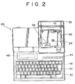
- FIG. 2 A printing device which the tape cassette is suitable for coupling to is shown in Fig. 2.
- the printing device 40 includes:
- a hinged accommodation cover 52 is provided to cover the chamber of the accommodation unit for the tape cassette 10 at the rear portion of the printing device 40.
- the tape cassette 10 is attachable/detachable when the accommodation cover 52 is hinged opened.
- Fig. 3 schematically shows the cassette accommodation unit 50.
- a ribbon winding shaft 54 extends upwardly.
- the ribbon winding shaft 54 is rotatably driven by a pulse motor and is arranged to engage the ribbon winding spool 30 of the tape cassette 10 (when the cassette is attached to the unit 50) to rotate the ribbon winding spool 30 in order to wind the ink ribbon 22 onto the spool 30.
- a tape drive shaft 56 also extends upwardly and is arranged to engage the tape drive roller 34 to rotate the same.
- the tape drive shaft 56 is engaged with a motor (not shown) through a gear transmission mechanism (not shown).
- a thermal print head 58 and platen roller 60 are oppositely positioned and the abovementioned tape feed roller 62 is arranged to cooperate with the tape drive roller 34 to feed the adhered tape T.
- the platen roller 60 and feed roller 62 are supported by a roller holder and are switchable between a print position and a release position by a switch mechanism (not shown).
- This switch mechanism may be as described in Japanese Patent Provisional Publication HEI 3283814 and accordingly a description thereof is omitted here.
- the above thermal print head 58 includes a plurality of heating elements for printing images, such as characters and the like, on the film tape 18 using the ink ribbon 22.
- a tape cutter 64 is also disposed at a position adjacent to one side of the cassette accommodation unit 50 to cut the adhered tape T discharged from the tape exit slit 32 of the tape cassette 10.
- the tape cutter 64 is composed of a fixed blade 66 and movable blade 68 on opposite sides of the path of the tape T.
- the fixed blade 66 is fixedly arranged at a position adjacent to the tape exit slit 32, and the movable blade 68 is movably positioned at a position away from the tape exit slit 32.
- the mechanism for driving the tape cutter 64 transmits the drive force of a motor to the movable blade 68 through a gear mechanism to move the movable blade 86 about its fulcrum.
- the adhered tape T is cut off by the closing operation of the movable blade 68 in association with the fixed blade 66.
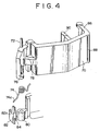
- a tension lever 70 for stretching the above ink ribbon 22 is rotatably disposed about a shaft 72 as shown in Fig. 1. As shown in detail in Figs. 4 to 7, an end of the shaft 72 is inserted into a cylindrical shaft receiving hole 80 provided on the inner bottom surface of the lower case member 14.
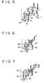
- a torsion spring 74 through which the support shaft 72 extends, engage against stepped portions 76, 78 of the tension lever 70, as shown in Fig. 5.
- stepped portions 76, 78 of the tension lever 70 On inserting the end of shaft 72 into hole 80, as shown in Fig. 6, one end of the spring 74a of the above torsion spring 74 slides down along the slanted surface 82a of a piece 82 which is provided on the inner bottom surface of the lower case member 14 (See Fig. 6) and is then locked by engaging below a hook portion 84 formed below the slanted surface (See Fig. 7). With this arrangement, the tension lever 70 is urged by the torsion spring 74 to rotate anti-clockwise in Fig. 1 about the support shaft 72.
- the end of the support shaft 72 of the tension lever 70 is inserted into the cylindrical shaft receiving hole 80 after the torsion spring 74 has been mounted to the support shaft 72.
- the torsion spring 74 is prevented from coming off the support shaft 72, aiding assembly.
- a bent portion 86 extends from the extreme end of the tension lever 70 to abut against the ink ribbon 22.
- the ink ribbon 22 is arranged to pass over an externally projecting edge 88 of the bent portion 86 before being wound onto the ribbon winding spool 30.
- a contact piece 90 projects from a middle portion of the tension lever 70 to confront the backside of the thermal print head 58 when the tape cassette 10 is attached to the cassette accommodation unit 50.
- camming means in the form of a pair of inclined pieces 92a and 92b having different heights, are disposed in parallel on the backside of the thermal print head 40.
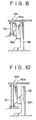
- the contact piece 90a in the case of a thin cassette 10A containing a narrow tape 18, the contact piece 90a is arranged to engage the higher inclined piece 92a, as shown in Figs. 8, 9A and 9B.
- the contact piece 90B is arranged to engage the lower inclined piece 92a, as shown in Figs. 10, 11A and 11B.
- the contact piece 90a engages with the higher inclined piece 92a on the backside of the thermal print head 58 at an early stage, as shown in Figs. 9A and 9B. Therefore, the tension lever 70 begins to be rotated relatively early.
- the thick tape cassette 10B is attached, because the contact piece 90b of the tension lever 70 engages with the lower inclined piece 92b at a later stage than in the case of the thin tape cassette 10A, as shown in Figs. 11A, 11B, the tension lever 70 begins to be rotated relatively later in time.
- This release timing is earlier when the thin tape cassette 10A is used than when the wide tape cassette 10B is used. If it were early when the thick tape cassette 10B is used, there is a possibility that the ink ribbon 22 would catch the edge of the thermal print head 58 when the cassette is removed, and therefore the release timing when thick tape cassette 10B is used is delayed with respect to the case when the narrow tape cassette 10A is used.
- the contact pieces 90a, 90b have upwardly inclined surfaces at the lower edges thereof, and the inclined pieces 92a, 92b have downwardly inclined surfaces at the upper edges thereof to correspond with the upwardly inclined surfaces.
- the above-described inclination of the surfaces causes the contact pieces 90a, 90b to slide along the inclined surfaces of the inclined pieces 92a, 92b respectively to smoothly rotate the tension lever 70.
- the depth of projection of the contact piece 90 is set in accordance with the kind of an ink used in the ink ribbon 22.
- the ink used for the ink ribbon 22 may be, for example, of a wax type or a resin type. If the ink is of the resin type, ink deposited in printing cools and solidifies in a relatively short time period after it has been printed. As a result the ink ribbon must be exfoliated by a large amount. To achieve this, the contact piece 90 has a large projection depth so that the film tape is exfoliated from the ink ribbon at a large exfoliating angle.
- the ink is of the wax type, the time necessary for the ink to cool and solidify is not so short, and thus the exfoliating angle should be small to provide sufficient time for the ink ribbon 22 to be fixedly adhered to the film tape.
- a clutch coil spring 94 is attached to the base portion of the ribbon winding spool 30. Although an end of the clutch coil spring 94 is pressed against the ribbon winding spool 30, the other end thereof is locked by the locking piece 96 on the lower case member 14. Consequently, when a tension larger than a predetermined value is applied to the ribbon winding spool 30 when printing, the ribbon winding spool 30 may be idly rotated by slippage of the above clutch coil spring 94 to adjust the winding torque.
- the upper cover member is thus securely engaged to the lower case member by an engagement portion and a locking piece, which are provided on one and the other of the extreme end of the shaft provided on the lower case member and the upper cover member.
- the tape cassette is not deformed by the expansion of the release paper due to the influence of a temperature, humidity and the like.
- protruding means in the form of a bill-shaped tape receiving portion 36 is provided at the tape exit slit 32 of the tape cassette 10 and extends, in the general direction of the path in which tape T is, in use, fed, to the vicinity of the extreme end of the fixed blade 66.Thus, the extreme end of the tape T fed through the tape exit slit 32 of the tape cassette 10 is guided to the ends of both the fixed blade 66 and the movable scissor blade 68 of the tape cutter 64.
- the amount of tape T projecting from the tape exit slit 32 and extending beyond the tape receiving portion 36 is advantageously less than the thickness of the lower case member at the side of the slit 32, which thickness is increased by the tape receiving portion 36.
- the extreme, cut end of the adhered tape T on the tape cassette 10 side is held on the surface of the tape receiving portion 36. Consequently, even if the extreme, cut end of the adhered tape T is inadvertently pulled or pushed in the direction of the interior of the cassette case, the tape T can be pulled out again as the extreme cut end of the adhered tape T will not be lost within the cassette case.
- the extreme end of the film tape remaining in the cassette case after having been printed and fed out of the tape exit is received by and stopped at a bill-shaped tape receiving portion which extends from the tape exit of the tape cassette. Therefore, there is an advantage in that the tape cassette can be used without anxiety because the situation in which the end of the tape T is pulled or pushed into the main body of the cassette, and cannot thereafter be easily removed, can be substantially prevented.
- the cassette Whilst in the illustrated embodiment of cassette the cassette is illustrated as accommodating a recording tape, an ink ribbon and an adhesive tape, the cassette may comprise other numbers of tapes, including a single tape-like member or two tape-like members.
- the cassette may accommodate only a recording tape on which the image is to be printed by other than ink.
- the cassette may accommodate a recording tape in combination with either an ink ribbon tape (which is not fed from the exit aperture) or an adhesive tape (which is fed from the exit aperture with the recording tape).
Landscapes
- Impression-Transfer Materials And Handling Thereof (AREA)
- Handling Of Continuous Sheets Of Paper (AREA)
- Printers Characterized By Their Purpose (AREA)
Claims (18)
- Cassette à ruban (10) comportant un boîtier (16) ayant une paroi latérale et un élément analogue à un ruban (18) contenu dans le boîtier, ladite paroi latérale étant munie d'une ouverture (32) destinée à la sortie dudit élément analogue à un ruban à partir dudit boîtier le long d'un trajet d'acheminement vers une position de découpe (64) située à l'extérieur du boîtier, au niveau de laquelle l'extrémité de l'élément analogue à un ruban peut être coupée, ladite paroi latérale étant aussi munie de moyens formant saillie (36) adjacents à ladite ouverture de sortie (32) et s'étendant vers l'extérieur à partir d'une surface extérieure de ladite paroi latérale dans la direction de manière générale du trajet d'acheminement pour se terminer près de la position de découpe.
- Cassette selon la revendication 1, dans laquelle lesdits moyens formant saillie (36) s'étendent à travers à peu près toute l'étendue de ladite ouverture de sortie (32) dans une direction de manière générale perpendiculaire à la direction de trajet d'acheminement.
- Cassette à ruban selon la revendication 1 ou 2, dans laquelle ledit boîtier comporte un élément formant boîtier de réception principal (14) et un élément formant couvercle (12), et ladite cassette à ruban comporte de plus des moyens de prise (102) agencés sur un élément parmi ledit élément formant couvercle et ledit élément formant boîtier de réception et des moyens de réception (100) agencés sur l'autre élément parmi ledit élément formant couvercle et ledit élément de réception, lesdits moyens de prise et lesdits moyens de réception étant agencés pour coopérer lorsque ledit élément formant boîtier de réception et ledit élément formant couvercle sont mis ensemble pour fixer ledit élément formant couvercle sur ledit élément formant boitier de réception.
- Cassette selon la revendication 3, dans laquelle un élément parmi ledit élément formant boîtier de réception (14) et ledit élément formant couvercle (12) est muni de moyens formant arbre (98) destinés à recevoir sur celui-ci une bobine pouvant être mise en rotation (20) autour de laquelle est enroulé ledit élément analogue à un ruban, et dans laquelle l'un desdits moyens de prise et des moyens de réception est agencé sur l'extrémité desdits moyens formant arbre.
- Cassette selon la revendication 4, dans laquelle lesdits moyens formant arbre (98) sont agencés sur ledit élément formant boîtier de réception.
- Cassette selon l'une quelconque des revendications précédentes, dans laquelle ledit élément analogue à un ruban (18) est un ruban d'enregistrement destiné à l'impression sur celui-ci d'images, par un dispositif d'impression.
- Cassette selon la revendication 6, dans laquelle le boîtier de cassette comporte de plus un ruban encré (22) destiné à fournir une source d'encre pour l'impression d'images sur ledit ruban d'enregistrement (18).
- Cassette selon la revendication 6 ou 7, dans laquelle ledit boîtier de cassette comporte de plus un ruban adhésif (36) destiné à être collé sur ledit ruban d'enregistrement (18) après impression des images sur ledit ruban d'enregistrement.
- Cassette selon la revendication 8, dans laquelle une extrémité dudit ruban adhésif (36) sort dudit boîtier de cassette à travers ladite ouverture (32) lorsqu'il colle audit ruban d'enregistrement.
- Cassette selon l'une quelconque des revendications 6 à 9, dans laquelle ledit ruban d'enregistrement (18) est constitué d'un ruban transparent.
- Cassette selon l'une quelconque des revendications 8 à 10, dans laquelle ledit ruban adhésif (26) est constitué d'un ruban adhésif double-face.
- Cassette selon l'une quelconque des revendications 1 à 6, dans laquelle ledit boîtier de cassette (16) comporte plusieurs éléments analogues à un ruban (18, 22, 26), au moins deux (18, 26) desdits plusieurs éléments analogues à un ruban étant agencés pour sortir dudit boîtier de cassette à travers ladite ouverture de sortie (32).
- Cassette selon la revendication 3, dans laquelle ledit boîtier de cassette reçoit plusieurs éléments analogues à un ruban (18, 22, 26) enroulés autour de bobines (20, 28, 30),dans laquelle ledit élément formant boîtier de réception (14) est muni de plusieurs arbres (98), chacune desdites bobines étant agencée sur un arbre différent parmi lesdits plusieurs arbres,dans laquelle lesdits moyens de prise (102) comportent plusieurs éléments de prise dont chacun est agencé sur ledit élément formant couvercle (12) ou sur une extrémité d'un arbre parmi lesdits plusieurs arbres (98), etdans laquelle lesdits moyens de réception (100) comportent plusieurs éléments de réception destinés à coopérer avec lesdits plusieurs moyens de prise (102), chacun desdits éléments de réception étant agencé sur une extrémité d'un arbre parmi lesdits plusieurs arbres (98) ou sur ledit élément formant couvercle en correspondance avec un élément de prise.
- Cassette à ruban selon la revendication 1 ou 2, dans laquelle ledit élément analogue à un ruban (18) est enroulé autour d'une bobine (20), ledit boîtier (16) comporte un élément formant boîtier de réception (14) muni d'un arbre, ladite bobine (20) étant agencée de manière rotative sur ledit arbre, et un élément formant couvercle (12) pour recouvrir ledit élément formant boîtier de réception, ladite ouverture de sortie (32) est formée dans ledit élément formant boîtier de réception, et ladite cassette à ruban (10) comporte de plus des moyens de prise (102) agencés sur l'un parmi l'extrémité dudit arbre et ledit élément formant couvercle, et des moyens de réception (100) agencés sur l'autre parmi ladite extrémité dudit arbre et ledit élément formant couvercle pour recevoir lesdits moyens de prise pour fixer ledit élément formant couvercle sur ledit élément formant boîtier de réception.
- Cassette à ruban selon l'une quelconque des revendications 3 à 5 ou 14, dans laquelle lesdits moyens de mise en prise (102) comportent au moins une paire d'éléments d'encliquetage (102a, 102b).
- Cassette à ruban selon l'une quelconque des revendications précédentes, comportant de plus des moyens de mise sous tension (70) pour mettre sous tension ledit élément analogue à un ruban (18) lorsque la cassette (10) est insérée à l'intérieur d'une chambre de réception de cassette d'un dispositif d'impression (40), lesdits moyens de mise sous tension (70) comportant un levier pouvant pivoter agencé pour pivoter vers une position de mise sous tension par l'action de moyens formant came agencés sur ceux-ci et des moyens formant came supplémentaires associés à la chambre de réception de cassette du dispositif d'impression.
- Combinaison d'une cassette selon l'une quelconque des revendications précédentes avec un dispositif d'impression (40), ledit dispositif d'impression étant muni de moyens de découpe (64) pour découper ledit élément analogue à un ruban au niveau de la position de découpe lorsque ladite cassette (10) est, en utilisation, agencée sur le dispositif d'impression.
- Combinaison selon la revendication 17, dans laquelle lesdits moyens de découpe (64) comportent une lame de découpe mobile (68) positionnée sur un premier côté dudit trajet d'acheminement de l'élément analogue à un ruban et une lame de découpe stationnaire (66) positionnée sur le côté opposé dudit trajet d'acheminement et lesdits moyens faisant saillie font saillie à partir de ladite paroi latérale du boîtier de cassette sur ledit premier côté dudit trajet d'acheminement.
Applications Claiming Priority (4)
| Application Number | Priority Date | Filing Date | Title |
|---|---|---|---|
| JP4020581A JP2666644B2 (ja) | 1992-01-08 | 1992-01-08 | テープカセット |
| JP20581/92 | 1992-01-08 | ||
| JP176957/92 | 1992-07-03 | ||
| JP17695792A JP3151943B2 (ja) | 1992-07-03 | 1992-07-03 | テープカセット |
Publications (3)
| Publication Number | Publication Date |
|---|---|
| EP0555954A2 EP0555954A2 (fr) | 1993-08-18 |
| EP0555954A3 EP0555954A3 (en) | 1994-06-15 |
| EP0555954B1 true EP0555954B1 (fr) | 1997-03-26 |
Family
ID=26357555
Family Applications (1)
| Application Number | Title | Priority Date | Filing Date |
|---|---|---|---|
| EP93300127A Expired - Lifetime EP0555954B1 (fr) | 1992-01-08 | 1993-01-08 | Cassette à bande |
Country Status (3)
| Country | Link |
|---|---|
| US (1) | US5350243A (fr) |
| EP (1) | EP0555954B1 (fr) |
| DE (1) | DE69309130T2 (fr) |
Cited By (10)
| Publication number | Priority date | Publication date | Assignee | Title |
|---|---|---|---|---|
| CN101934647A (zh) * | 2009-06-30 | 2011-01-05 | 兄弟工业株式会社 | 带盒 |
| US8764325B2 (en) | 2009-03-31 | 2014-07-01 | Brother Kogyo Kabushiki Kaisha | Tape cassette |
| US8770877B2 (en) | 2008-12-25 | 2014-07-08 | Brother Kogyo Kabushiki Kaisha | Tape printer |
| CN103978794A (zh) * | 2014-05-29 | 2014-08-13 | 无锡双龙信息纸有限公司 | 一种票据补号机 |
| US10201993B2 (en) | 2009-03-31 | 2019-02-12 | Brother Kogyo Kabushiki Kaisha | Tape cassette |
| US10226949B2 (en) | 2009-03-31 | 2019-03-12 | Brother Kogyo Kabushiki Kaisha | Tape cassette |
| US10265976B2 (en) | 2009-12-16 | 2019-04-23 | Brother Kogyo Kabushiki Kaisha | Tape cassette |
| US10661589B2 (en) | 2008-12-25 | 2020-05-26 | Brother Kogyo Kabushiki Kaisha | Tape cassette |
| US11135862B2 (en) | 2009-12-28 | 2021-10-05 | Brother Kogyo Kabushiki Kaisha | Tape cassette with indicator portion having pressing and non-pressing portion for indentifying tape type |
| US12296580B2 (en) | 2009-03-31 | 2025-05-13 | Brother Kogyo Kabushiki Kaisha | Tape cassette |
Families Citing this family (32)
| Publication number | Priority date | Publication date | Assignee | Title |
|---|---|---|---|---|
| US5595447A (en) | 1992-10-13 | 1997-01-21 | Seiko Epson Corporation | Tape cartridge and printing device having print medium cartridge |
| USD361342S (en) | 1993-08-19 | 1995-08-15 | Brother Kogyo Kabushiki Kaisha | Tape cartridge for tape printer |
| USD362015S (en) | 1993-08-19 | 1995-09-05 | Brother Kogyo Kabushiki Kaisha | Tape cartridge for tape printer |
| US6042280A (en) * | 1995-05-25 | 2000-03-28 | Brother Kogyo Kabushiki Kaisha | Tape label printing device |
| US6190069B1 (en) | 1994-05-25 | 2001-02-20 | Brother Kogyo Kabushiki Kaisha | Tape-shaped label printing device |
| US6196740B1 (en) | 1994-05-25 | 2001-03-06 | Brother Kogyo Kabushiki Kaisha | Tape-shaped label printing device |
| JP3212445B2 (ja) * | 1994-05-25 | 2001-09-25 | ブラザー工業株式会社 | テープカセット |
| JP3111445B2 (ja) * | 1995-03-29 | 2000-11-20 | ブラザー工業株式会社 | テープ状ラベル作成装置 |
| JP3064814B2 (ja) * | 1994-07-28 | 2000-07-12 | ブラザー工業株式会社 | テープカセット |
| JP3333324B2 (ja) * | 1994-08-23 | 2002-10-15 | セイコーエプソン株式会社 | テープカートリッジおよびテープ印字装置 |
| US5853254A (en) * | 1994-12-15 | 1998-12-29 | Seiko Epson Corporation | Tape cartridge for use in a tape printer |
| US6132120A (en) * | 1995-03-29 | 2000-10-17 | Brother Kogyo Kabushiki Kaisha | Tape-shaped label printing device |
| USD372269S (en) | 1995-09-14 | 1996-07-30 | Casio Computer Co., Ltd. | Tape cartridge for electronic label printer |
| JP3564848B2 (ja) * | 1996-02-16 | 2004-09-15 | ブラザー工業株式会社 | テープカセット |
| JP3610158B2 (ja) * | 1996-04-05 | 2005-01-12 | セイコーエプソン株式会社 | テープリール装置およびこれを備えたテープカートリッジ |
| DE69727580T2 (de) | 1997-11-27 | 2004-07-08 | Esselte N.V. | Nachfüllbare Farbbandkassette |
| JP4543601B2 (ja) * | 1999-08-06 | 2010-09-15 | ブラザー工業株式会社 | テープ供給カートリッジ |
| JP4947085B2 (ja) * | 2009-03-31 | 2012-06-06 | ブラザー工業株式会社 | テープカセット |
| PL2414165T3 (pl) * | 2009-03-31 | 2014-08-29 | Brother Ind Ltd | Kaseta z taśmą oraz drukarka taśmowa |
| CN101850662B (zh) | 2009-03-31 | 2015-02-11 | 兄弟工业株式会社 | 带式打印装置 |
| JP5136503B2 (ja) | 2009-03-31 | 2013-02-06 | ブラザー工業株式会社 | テープカセット |
| EP2261040B1 (fr) * | 2009-06-10 | 2012-02-08 | Brother Kogyo Kabushiki Kaisha | Imprimante |
| US20100329767A1 (en) * | 2009-06-30 | 2010-12-30 | Brother Kogyo Kabushiki Kaisha | Tape cassette |
| JP5326950B2 (ja) * | 2009-09-09 | 2013-10-30 | ブラザー工業株式会社 | テープカセット |
| JP5093265B2 (ja) * | 2010-02-26 | 2012-12-12 | ブラザー工業株式会社 | テープカセット |
| US8384750B2 (en) | 2010-03-31 | 2013-02-26 | Brother Kogyo Kabushiki Kaisha | Printing apparatus |
| EP2371558B1 (fr) | 2010-03-31 | 2015-04-15 | Brother Kogyo Kabushiki Kaisha | Imprimante thermique |
| USD679752S1 (en) * | 2010-11-19 | 2013-04-09 | Domino Printing Sciences Plc | Printer tape cassette |
| USD656541S1 (en) | 2011-03-16 | 2012-03-27 | SK2 Technology Limited | Label printer cartridge |
| CN103660643A (zh) * | 2012-09-25 | 2014-03-26 | 昆山尚达智机械有限公司 | 一种新型的打码机 |
| EP2977218B1 (fr) * | 2013-03-21 | 2018-11-07 | Seiko Epson Corporation | Cartouche de bande et imprimante de bande |
| USD933744S1 (en) * | 2019-06-28 | 2021-10-19 | Seiko Epson Corporation | Tape cartridge for a label printer |
Citations (1)
| Publication number | Priority date | Publication date | Assignee | Title |
|---|---|---|---|---|
| EP0410259A1 (fr) * | 1989-07-17 | 1991-01-30 | Kroy Inc. | Appareil à thermo-impression et cartouche d'alimentation en bande à cet effet |
Family Cites Families (16)
| Publication number | Priority date | Publication date | Assignee | Title |
|---|---|---|---|---|
| US3075627A (en) * | 1961-10-02 | 1963-01-29 | Syracuse Stamping Company Inc | Inked ribbon cartridge casing |
| US4006493A (en) * | 1975-05-19 | 1977-02-01 | Gerry Martin E | Tape cassette |
| DE2655832C2 (de) * | 1976-12-07 | 1983-12-15 | Mannesmann AG, 4000 Düsseldorf | Trennvorrichtung zum Abtrennen von Papierbahnen in einem Drucker |
| JPS6019573A (ja) * | 1983-07-13 | 1985-01-31 | Tokyo Electric Co Ltd | プリンタのペ−パ−切傷防止装置 |
| US4830522A (en) * | 1985-02-13 | 1989-05-16 | Kabushiki Kaisha Sato | Electronic hand labeler with thermal printer and plural cutters |
| JPS63306067A (ja) * | 1987-06-08 | 1988-12-14 | スター精密株式会社 | 熱転写プリンタ− |
| JPH0634126Y2 (ja) * | 1987-11-28 | 1994-09-07 | ブラザー工業株式会社 | 剥離紙付き印字テープ切断機構を備えた印字装置 |
| US4815874A (en) * | 1988-02-01 | 1989-03-28 | Kroy Inc. | Thermal printer and tape-ribbon cartridge with cut-off mechanism |
| JPH0272039A (ja) * | 1988-09-02 | 1990-03-12 | Shinsei Ind:Kk | 卓上型ラベル印刷機 |
| US5188469A (en) * | 1988-10-14 | 1993-02-23 | Brother Kogyo Kabushiki Kaisha | Tape feed cassette with tape cutter and guide |
| JPH02106555A (ja) * | 1988-10-14 | 1990-04-18 | Brother Ind Ltd | テープ収納カセット |
| US4887110A (en) * | 1989-01-12 | 1989-12-12 | Eastman Kodak Company | Film cassette |
| JPH032868A (ja) * | 1989-05-31 | 1991-01-09 | Fuji Photo Film Co Ltd | 感光性平版印刷版 |
| US5115322A (en) * | 1989-06-30 | 1992-05-19 | Samsung Electronics Co., Ltd. | Guiding mechanism for a facsimile for preventing jam of heat-sensitive recording paper |
| US5174670A (en) * | 1990-03-29 | 1992-12-29 | Brother Kogyo Kabushiki Kaisha | Tape printer with end trimming cutter |
| JP2532387Y2 (ja) * | 1990-12-06 | 1997-04-16 | ブラザー工業株式会社 | テープ切断装置 |
-
1993
- 1993-01-06 US US08/001,099 patent/US5350243A/en not_active Expired - Lifetime
- 1993-01-08 DE DE69309130T patent/DE69309130T2/de not_active Expired - Lifetime
- 1993-01-08 EP EP93300127A patent/EP0555954B1/fr not_active Expired - Lifetime
Patent Citations (1)
| Publication number | Priority date | Publication date | Assignee | Title |
|---|---|---|---|---|
| EP0410259A1 (fr) * | 1989-07-17 | 1991-01-30 | Kroy Inc. | Appareil à thermo-impression et cartouche d'alimentation en bande à cet effet |
Cited By (27)
| Publication number | Priority date | Publication date | Assignee | Title |
|---|---|---|---|---|
| US10661589B2 (en) | 2008-12-25 | 2020-05-26 | Brother Kogyo Kabushiki Kaisha | Tape cassette |
| US12304229B2 (en) | 2008-12-25 | 2025-05-20 | Brother Kogyo Kabushiki Kaisha | Tape cassette |
| US8770877B2 (en) | 2008-12-25 | 2014-07-08 | Brother Kogyo Kabushiki Kaisha | Tape printer |
| US12233641B2 (en) | 2008-12-25 | 2025-02-25 | Brother Kogyo Kabushiki Kaisha | Tape cassette |
| US11479053B2 (en) | 2008-12-25 | 2022-10-25 | Brother Kogyo Kabushiki Kaisha | Tape cassette |
| US11285749B2 (en) | 2008-12-25 | 2022-03-29 | Brother Kogyo Kabushiki Kaisha | Tape cassette |
| US10226949B2 (en) | 2009-03-31 | 2019-03-12 | Brother Kogyo Kabushiki Kaisha | Tape cassette |
| US10201993B2 (en) | 2009-03-31 | 2019-02-12 | Brother Kogyo Kabushiki Kaisha | Tape cassette |
| US10618325B2 (en) | 2009-03-31 | 2020-04-14 | Brother Kogyo Kabushiki Kaisha | Tape cassette |
| US8764325B2 (en) | 2009-03-31 | 2014-07-01 | Brother Kogyo Kabushiki Kaisha | Tape cassette |
| US10675894B2 (en) | 2009-03-31 | 2020-06-09 | Brother Kogyo Kabushiki Kaisha | Tape cassette |
| US10744802B2 (en) | 2009-03-31 | 2020-08-18 | Brother Kogyo Kabushiki Kaisha | Tape cassette |
| US11052685B2 (en) | 2009-03-31 | 2021-07-06 | Brother Kogyo Kabushiki Kaisha | Tape cassette |
| US12296580B2 (en) | 2009-03-31 | 2025-05-13 | Brother Kogyo Kabushiki Kaisha | Tape cassette |
| US12257827B2 (en) | 2009-03-31 | 2025-03-25 | Brother Kogyo Kabushiki Kaisha | Tape cassette |
| US11945217B2 (en) | 2009-03-31 | 2024-04-02 | Brother Kogyo Kabushiki Kaisha | Tape cassette |
| US11254149B2 (en) | 2009-03-31 | 2022-02-22 | Brother Kogyo Kabushiki Kaisha | Tape cassette |
| US11707938B2 (en) | 2009-03-31 | 2023-07-25 | Brother Kogyo Kabushiki Kaisha | Tape cassette |
| US12194765B2 (en) | 2009-06-30 | 2025-01-14 | Brother Kogyo Kabushiki Kaisha | Tape cassette |
| US11225099B2 (en) | 2009-06-30 | 2022-01-18 | Brother Kogyo Kabushiki Kaisha | Tape cassette |
| CN101934647A (zh) * | 2009-06-30 | 2011-01-05 | 兄弟工业株式会社 | 带盒 |
| US10265976B2 (en) | 2009-12-16 | 2019-04-23 | Brother Kogyo Kabushiki Kaisha | Tape cassette |
| US11235600B2 (en) | 2009-12-16 | 2022-02-01 | Brother Kogyo Kabushiki Kaisha | Tape cassette |
| US12128697B2 (en) | 2009-12-28 | 2024-10-29 | Brother Kogyo Kabushiki Kaisha | Tape cassette |
| US11135862B2 (en) | 2009-12-28 | 2021-10-05 | Brother Kogyo Kabushiki Kaisha | Tape cassette with indicator portion having pressing and non-pressing portion for indentifying tape type |
| CN103978794B (zh) * | 2014-05-29 | 2017-01-18 | 无锡双龙信息纸有限公司 | 一种票据补号机 |
| CN103978794A (zh) * | 2014-05-29 | 2014-08-13 | 无锡双龙信息纸有限公司 | 一种票据补号机 |
Also Published As
| Publication number | Publication date |
|---|---|
| US5350243A (en) | 1994-09-27 |
| DE69309130D1 (de) | 1997-04-30 |
| EP0555954A3 (en) | 1994-06-15 |
| DE69309130T2 (de) | 1997-08-28 |
| EP0555954A2 (fr) | 1993-08-18 |
Similar Documents
| Publication | Publication Date | Title |
|---|---|---|
| EP0555954A2 (fr) | Cassette à bande | |
| EP0641663B1 (fr) | Imprimante pour ruban | |
| EP0684143B1 (fr) | Cassette à ruban | |
| EP1707395B1 (fr) | Cassette à bande | |
| US5348406A (en) | Tape feed mechanism with tape cutter and guide | |
| EP1698476B1 (fr) | Imprimante sur bande | |
| JP2985911B2 (ja) | テープ印字装置におけるテープカセット装着構造 | |
| US5645360A (en) | Tape cassette used in tape printing apparatus | |
| JPH06227102A (ja) | テープ巻取り機構 | |
| JP3448263B2 (ja) | テープカセット | |
| JP2003146493A (ja) | ロール紙保持装置およびプリンタ | |
| EP0630756B1 (fr) | Agrégat de ruban interchangeable | |
| JPH08183204A (ja) | テープ印字装置 | |
| JP2666644B2 (ja) | テープカセット | |
| US5615960A (en) | Tape printing apparatus having a slot for insertion of a tape cassette | |
| JP3617146B2 (ja) | 印刷装置 | |
| EP3991980B1 (fr) | Système d'imprimante et cassette | |
| JP3151943B2 (ja) | テープカセット | |
| JP3472203B2 (ja) | テープ印字装置及びインクリボンカセット | |
| JP2606462B2 (ja) | テープカートリッジ | |
| JPH0675748U (ja) | テーププリンタ装置 | |
| JP2522877Y2 (ja) | テープ印字装置 | |
| JP3579939B2 (ja) | 被印字媒体の切断装置 | |
| JP2666644C (fr) | ||
| JP2000062303A (ja) | リボンカートリッジにおける制動装置およびこれを備えたリボンカートリッジ |
Legal Events
| Date | Code | Title | Description |
|---|---|---|---|
| PUAI | Public reference made under article 153(3) epc to a published international application that has entered the european phase |
Free format text: ORIGINAL CODE: 0009012 |
|
| AK | Designated contracting states |
Kind code of ref document: A2 Designated state(s): BE DE FR GB |
|
| RHK1 | Main classification (correction) |
Ipc: B41J 32/00 |
|
| PUAL | Search report despatched |
Free format text: ORIGINAL CODE: 0009013 |
|
| AK | Designated contracting states |
Kind code of ref document: A3 Designated state(s): BE DE FR GB |
|
| 17P | Request for examination filed |
Effective date: 19940801 |
|
| 17Q | First examination report despatched |
Effective date: 19950803 |
|
| GRAG | Despatch of communication of intention to grant |
Free format text: ORIGINAL CODE: EPIDOS AGRA |
|
| GRAH | Despatch of communication of intention to grant a patent |
Free format text: ORIGINAL CODE: EPIDOS IGRA |
|
| GRAH | Despatch of communication of intention to grant a patent |
Free format text: ORIGINAL CODE: EPIDOS IGRA |
|
| GRAA | (expected) grant |
Free format text: ORIGINAL CODE: 0009210 |
|
| AK | Designated contracting states |
Kind code of ref document: B1 Designated state(s): BE DE FR GB |
|
| ET | Fr: translation filed | ||
| REF | Corresponds to: |
Ref document number: 69309130 Country of ref document: DE Date of ref document: 19970430 |
|
| PLBE | No opposition filed within time limit |
Free format text: ORIGINAL CODE: 0009261 |
|
| 26N | No opposition filed | ||
| REG | Reference to a national code |
Ref country code: GB Ref legal event code: IF02 |
|
| PGFP | Annual fee paid to national office [announced via postgrant information from national office to epo] |
Ref country code: GB Payment date: 20101215 Year of fee payment: 19 |
|
| PGFP | Annual fee paid to national office [announced via postgrant information from national office to epo] |
Ref country code: FR Payment date: 20120111 Year of fee payment: 20 |
|
| PGFP | Annual fee paid to national office [announced via postgrant information from national office to epo] |
Ref country code: DE Payment date: 20120131 Year of fee payment: 20 |
|
| PGFP | Annual fee paid to national office [announced via postgrant information from national office to epo] |
Ref country code: BE Payment date: 20120222 Year of fee payment: 20 |
|
| REG | Reference to a national code |
Ref country code: DE Ref legal event code: R071 Ref document number: 69309130 Country of ref document: DE |
|
| REG | Reference to a national code |
Ref country code: GB Ref legal event code: PE20 Expiry date: 20130107 |
|
| BE20 | Be: patent expired |
Owner name: *BROTHER KOGYO K.K. Effective date: 20130108 |
|
| PG25 | Lapsed in a contracting state [announced via postgrant information from national office to epo] |
Ref country code: GB Free format text: LAPSE BECAUSE OF EXPIRATION OF PROTECTION Effective date: 20130107 Ref country code: DE Free format text: LAPSE BECAUSE OF EXPIRATION OF PROTECTION Effective date: 20130109 |