EP0556543B1 - Chariot de manutention - Google Patents
Chariot de manutention Download PDFInfo
- Publication number
- EP0556543B1 EP0556543B1 EP93100166A EP93100166A EP0556543B1 EP 0556543 B1 EP0556543 B1 EP 0556543B1 EP 93100166 A EP93100166 A EP 93100166A EP 93100166 A EP93100166 A EP 93100166A EP 0556543 B1 EP0556543 B1 EP 0556543B1
- Authority
- EP
- European Patent Office
- Prior art keywords
- fork
- roller
- vehicle
- piston
- spring
- Prior art date
- Legal status (The legal status is an assumption and is not a legal conclusion. Google has not performed a legal analysis and makes no representation as to the accuracy of the status listed.)
- Expired - Lifetime
Links
Images

Classifications
-
- B—PERFORMING OPERATIONS; TRANSPORTING
- B60—VEHICLES IN GENERAL
- B60B—VEHICLE WHEELS; CASTORS; AXLES FOR WHEELS OR CASTORS; INCREASING WHEEL ADHESION
- B60B33/00—Castors in general ; Anti-clogging castors
- B60B33/04—Castors in general ; Anti-clogging castors adjustable, e.g. in height; linearly shifting castors
-
- B—PERFORMING OPERATIONS; TRANSPORTING
- B62—LAND VEHICLES FOR TRAVELLING OTHERWISE THAN ON RAILS
- B62B—HAND-PROPELLED VEHICLES, e.g. HAND CARTS OR PERAMBULATORS; SLEDGES
- B62B3/00—Hand carts having more than one axis carrying transport wheels; Steering devices therefor; Equipment therefor
- B62B3/04—Hand carts having more than one axis carrying transport wheels; Steering devices therefor; Equipment therefor involving means for grappling or securing in place objects to be carried; Loading or unloading equipment
- B62B3/06—Hand carts having more than one axis carrying transport wheels; Steering devices therefor; Equipment therefor involving means for grappling or securing in place objects to be carried; Loading or unloading equipment for simply clearing the load from the ground
-
- F—MECHANICAL ENGINEERING; LIGHTING; HEATING; WEAPONS; BLASTING
- F16—ENGINEERING ELEMENTS AND UNITS; GENERAL MEASURES FOR PRODUCING AND MAINTAINING EFFECTIVE FUNCTIONING OF MACHINES OR INSTALLATIONS; THERMAL INSULATION IN GENERAL
- F16F—SPRINGS; SHOCK-ABSORBERS; MEANS FOR DAMPING VIBRATION
- F16F9/00—Springs, vibration-dampers, shock-absorbers, or similarly-constructed movement-dampers using a fluid or the equivalent as damping medium
- F16F9/06—Springs, vibration-dampers, shock-absorbers, or similarly-constructed movement-dampers using a fluid or the equivalent as damping medium using both gas and liquid
- F16F9/064—Units characterised by the location or shape of the expansion chamber
-
- F—MECHANICAL ENGINEERING; LIGHTING; HEATING; WEAPONS; BLASTING
- F16—ENGINEERING ELEMENTS AND UNITS; GENERAL MEASURES FOR PRODUCING AND MAINTAINING EFFECTIVE FUNCTIONING OF MACHINES OR INSTALLATIONS; THERMAL INSULATION IN GENERAL
- F16F—SPRINGS; SHOCK-ABSORBERS; MEANS FOR DAMPING VIBRATION
- F16F9/00—Springs, vibration-dampers, shock-absorbers, or similarly-constructed movement-dampers using a fluid or the equivalent as damping medium
- F16F9/30—Springs, vibration-dampers, shock-absorbers, or similarly-constructed movement-dampers using a fluid or the equivalent as damping medium with solid or semi-solid material, e.g. pasty masses, as damping medium
- F16F9/303—Springs, vibration-dampers, shock-absorbers, or similarly-constructed movement-dampers using a fluid or the equivalent as damping medium with solid or semi-solid material, e.g. pasty masses, as damping medium the damper being of the telescopic type
-
- B—PERFORMING OPERATIONS; TRANSPORTING
- B62—LAND VEHICLES FOR TRAVELLING OTHERWISE THAN ON RAILS
- B62B—HAND-PROPELLED VEHICLES, e.g. HAND CARTS OR PERAMBULATORS; SLEDGES
- B62B2301/00—Wheel arrangements; Steering; Stability; Wheel suspension
- B62B2301/08—Wheel arrangements; Steering; Stability; Wheel suspension comprising additional wheels to increase stability
Definitions
- the invention relates to an industrial truck according to the preamble of patent claim 1.
- a shock absorber for various vehicles such as engines, construction machines, cranes or the like has become known, in which a hydraulic cylinder filled with compressible elastomer is provided, the piston of which has throttle bores and which forms a throttled passage with the cylinder wall.
- the suspension of the support rollers turns the vehicle into an oscillatory system that can be excited to undesired vibrations under certain operating conditions.
- pedestrian-controlled pallet trucks tend to tip over an axis that runs essentially in the longitudinal direction of the vehicle when driving with little or no load. Prevent the tilting vibrations the full utilization of the available driving speed. The result is a reduction in throughput.
- the invention is therefore based on the object of designing an industrial truck in such a way that disruptive vibrations of the vehicle are prevented or at least rapidly subside.
- a spring damping element is formed by a hydraulic cylinder filled with a viscous, compressible elastomer with a piston rod on one side, the piston of which has at least one throttle bore and / or forms a throttle gap with the cylinder wall.
- the piston penetrates the cylinder, the chamber volume is reduced, which compresses the elastomer and increases the internal pressure. This creates a force that tries to push the piston out of the cylinder.
- the elastomer is also, for example, through a gap pressed; mechanical energy is reduced as a result of the internal friction of the elastomer, and a speed-dependent force acts counter to the direction of movement, which is decisive for the damping effect.
- Such a damping element has the advantage that it is extremely compact and can be used in an advantageous manner even in confined spaces. Since it consists of one unit, assembly is also extremely easy.
- the spring and damping constants can be calculated from the geometric parameters of the cylinder and the rheological material sizes of the elastomer using known formulas.
- a low-lift pallet truck S 10 has four support rollers 12, 14, 16 and 18, of which the first two can be tilted about a horizontal axis and rotatable about a vertical axis by means of a roller fork 20; the tilting is cushioned and damped by a spring damping element, not shown.
- the other support rollers 16, 18 are mounted on a rocker arm 22 which can be pivoted with the aid of a control rod 24 in order to raise the fork arms 26, 28 in a known manner.
- a drive wheel 30 is arranged between the support rollers 12, 14 and is driven by a motor indicated at 32. In addition, the drive wheel 30 can be pivoted with the aid of a drawbar indicated at 34, which also contains control elements for raising or lowering the fork arms 26, 28 and the drive motor 32.
- FIGs 2 and 3 are examples of storage the support rollers 12, 14 shown.
- Fig. 2 shows a support roller 36 which is mounted on an L-shaped fork 38, which in turn is guided vertically at 40.
- the fork 38 is supported on a vehicle-mounted abutment 42 with the aid of a spring damping element 44.
- the spring damping element 44 is arranged between a fork 46 and a vertically guided bearing component 48 which is guided in the bearing 40 fixed to the vehicle is.
- the spring damping element 44 in both embodiments according to FIGS. 2 and 3 causes a resilient and at the same time damped support of the support roller 36, so that, for example in the industrial truck according to FIG. 1, undesirable vibrations which do not allow the maximum speed to be used are suppressed will.
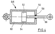
- Fig. 4 the spring damping element 44 is shown alone, in which a piston 52 is arranged in a cylinder 50, which has a throttle gap 54 to the cylinder wall.
- the piston rod 56 led out on one side is sealed at 58.
- Located in cylinder 50 an elastomeric compressible liquid 60. If, for example, the piston 52 is moved into the cylinder 50, the displaced volume increases, as a result of which the medium 60 is compressed and exerts a restoring force on the piston rod 56. At the same time, the medium squeezes through the throttle gap 54, whereby mechanical energy is converted into heat, which leads to a corresponding damping of the piston movement.
Landscapes
- Engineering & Computer Science (AREA)
- General Engineering & Computer Science (AREA)
- Mechanical Engineering (AREA)
- Chemical & Material Sciences (AREA)
- Combustion & Propulsion (AREA)
- Transportation (AREA)
- Vehicle Body Suspensions (AREA)
- Forklifts And Lifting Vehicles (AREA)
Claims (1)
- Véhicule de manutention au sol pourvu d'une roue d'entraînement (30), d'au moins une roulette d'appui (12, 14) près de la roue d'entraînement (30) et de roues de charge avant (16, 18) aux extrémités libres de parties horizontales de fourche (26, 28), la roulette d'appui (12, 14) étant montée rotative autour d'un axe horizontal dans une chape de roulette qui, au moyen d'une pièce formant palier, est montée pivotante autour d'un axe vertical et basculante autour d'un axe horizontal, et pourvu d'un ressort (50) entre la chape de roulette et la pièce formant palier ou le véhicule pour supporter élastiquement la roulette d'appui (12, 14), caractérisé en ce qu'un élément d'amortissement à ressort est prévu et est constitué d'un cylindre hydraulique (50) rempli d'un élastomère compressible (60) visqueux, dont le piston (52) comporte au moins un orifice d'étranglement et/ou forme une fente d'étranglement (54) avec une paroi du cylindre.
Applications Claiming Priority (2)
| Application Number | Priority Date | Filing Date | Title |
|---|---|---|---|
| DE4205150A DE4205150C2 (de) | 1992-02-20 | 1992-02-20 | Lenkrolle für Flurförderzeuge |
| DE4205150 | 1992-02-20 |
Publications (3)
| Publication Number | Publication Date |
|---|---|
| EP0556543A2 EP0556543A2 (fr) | 1993-08-25 |
| EP0556543A3 EP0556543A3 (en) | 1994-06-15 |
| EP0556543B1 true EP0556543B1 (fr) | 1997-07-16 |
Family
ID=6452162
Family Applications (1)
| Application Number | Title | Priority Date | Filing Date |
|---|---|---|---|
| EP93100166A Expired - Lifetime EP0556543B1 (fr) | 1992-02-20 | 1993-01-08 | Chariot de manutention |
Country Status (2)
| Country | Link |
|---|---|
| EP (1) | EP0556543B1 (fr) |
| DE (2) | DE4205150C2 (fr) |
Families Citing this family (11)
| Publication number | Priority date | Publication date | Assignee | Title |
|---|---|---|---|---|
| EP0662068A4 (fr) * | 1992-09-23 | 1996-01-03 | Pallet Boss Pty Ltd | Vehicules destines a transporter des charges. |
| DE4310257C2 (de) * | 1993-03-30 | 1995-02-23 | Jungheinrich Ag | Flurförderzeug |
| FR2716878B1 (fr) * | 1994-03-04 | 1996-04-26 | Mic | Chariot de manutention avec roues stabilisatrices. |
| US5628377A (en) * | 1995-06-16 | 1997-05-13 | M I C, Societe Anonyme | Goods-handling cart with stabilizing wheels |
| KR100383370B1 (ko) | 1999-02-08 | 2003-05-12 | 카야바 고교 가부시기가이샤 | 캐스터 |
| DE10022400C5 (de) * | 2000-04-20 | 2008-11-06 | Jungheinrich Ag | Gabelhubwagen mit einem Fünfradfahrwerk |
| DE102008047022A1 (de) | 2008-09-13 | 2010-03-18 | Jungheinrich Ag | Fahrwerk für ein Flurförderzeug |
| CN102849656A (zh) * | 2012-09-15 | 2013-01-02 | 侯如升 | 一种带减震装置的液压拖车 |
| US9593003B2 (en) * | 2014-04-01 | 2017-03-14 | The Raymond Corporation | Caster wheel with constant force mechanism |
| US10315900B2 (en) | 2014-04-01 | 2019-06-11 | The Raymond Corporation | Caster wheel with constant force mechanism |
| CN121292335A (zh) * | 2025-12-10 | 2026-01-09 | 湖南星舟重工科技有限公司 | 一种具有可调支撑轮的叉车 |
Family Cites Families (10)
| Publication number | Priority date | Publication date | Assignee | Title |
|---|---|---|---|---|
| DE1948685U (de) * | 1965-04-15 | 1966-10-27 | Hans Still Ges Mit Beschraenkt | Elektro-gabelhubwagen, insbesondere elektro-gabel-hochhubwagen. |
| GB1415232A (en) * | 1973-02-13 | 1975-11-26 | Automotive Prod Co Ltd | Vehicle suspension struts |
| US4000912A (en) * | 1975-02-21 | 1977-01-04 | Mse Corporation | Shock absorber |
| DE7930623U1 (fr) * | 1979-10-30 | 1980-02-07 | Jungheinrich Unternehmensverwaltung Kg, 2000 Hamburg | |
| PL122000B1 (en) * | 1979-11-08 | 1982-06-30 | Polskie Koleje Panstwowe Centralny Osrodek Badan I Rozwoju Techniki Kolejnictwa | Elastomeric shock absorber |
| JPS6093504U (ja) * | 1983-12-01 | 1985-06-26 | アップリカ葛西株式会社 | キヤスタ |
| GB2172373A (en) * | 1985-02-27 | 1986-09-17 | Furniture Ind Res Ass | Load lifting and support device |
| GB2187687A (en) * | 1985-11-19 | 1987-09-16 | Domestic & General Finance Co | Trailer with damped caster wheel |
| DE3612925A1 (de) * | 1986-04-17 | 1987-10-22 | Haco Rollen Vertrieb | Federnde lenkrolle |
| ES2033214T3 (es) * | 1987-06-09 | 1993-08-01 | Heinrich Blickle Gmbh & Co.Kg | Rodillo-guia elastico para cargas pesadas. |
-
1992
- 1992-02-20 DE DE4205150A patent/DE4205150C2/de not_active Expired - Fee Related
-
1993
- 1993-01-08 DE DE59306901T patent/DE59306901D1/de not_active Expired - Lifetime
- 1993-01-08 EP EP93100166A patent/EP0556543B1/fr not_active Expired - Lifetime
Also Published As
| Publication number | Publication date |
|---|---|
| EP0556543A3 (en) | 1994-06-15 |
| EP0556543A2 (fr) | 1993-08-25 |
| DE4205150C2 (de) | 1995-03-09 |
| DE4205150A1 (de) | 1993-08-26 |
| DE59306901D1 (de) | 1997-08-21 |
Similar Documents
| Publication | Publication Date | Title |
|---|---|---|
| DE60005147T2 (de) | Anordnung für eine fahrzeugkabine | |
| DE69531448T2 (de) | Hydraulische aufhängung mit unabhängiger regelung von nick- und rollbewegung | |
| DE69522434T2 (de) | Aufhängungssystem | |
| DE69431764T2 (de) | Lift-Achsen-Aufhängungssystem in Form eines Parallelogramms mit Steuerung der Achsen-Schwenkeinstellung | |
| EP0745043B1 (fr) | Compensateur de l'effet de plongee du au freinage | |
| EP0556543B1 (fr) | Chariot de manutention | |
| DE2246542B2 (de) | Federung für Fahrzeuge | |
| EP0238077A2 (fr) | Suspension d'une roue ou d'un essieu de véhicule | |
| DE69116515T2 (de) | Hydromechanische Steuerung | |
| DE19753412C2 (de) | Gabelhubwagen mit verstellbarer Stützrolle | |
| EP1588979B1 (fr) | Chariot de manutention, en particulier chariot élévateur à fourche | |
| EP1147968B2 (fr) | Transpalette à cinq roues | |
| EP0961726B1 (fr) | Systeme de relevage d'axe de vehicule a suspension pneumatique | |
| EP0620132A1 (fr) | Installation pour entraîner, guider et diriger une roue de véhicule | |
| EP0584704B1 (fr) | Véhicule à trois roues en particulier chariot de manutention | |
| DE69225225T2 (de) | Fahrzeugaufhängung | |
| DE3938773C2 (de) | Federbein-Radaufhängung für Kraftfahrzeuge | |
| DE4204783C2 (de) | Laufwerk für Schienenfahrzeuge | |
| EP1563200A1 (fr) | Dispositif d'amortissement pour roue sur pneumatique | |
| DE1580480A1 (de) | Unabhaengige Vorderradaufhaengung | |
| EP0743199B1 (fr) | Roulette pivotante | |
| DE9414724U1 (de) | Fahrzeug mit Ausgleichsvorrichtung | |
| WO1997023375A2 (fr) | Bogie de vehicule ferroviaire a deux essieux | |
| DE3606327C2 (fr) | ||
| DE3822811A1 (de) | Achsanordnung fuer ein kraftfahrzeug mit viskose-schwingungsdaempfer |
Legal Events
| Date | Code | Title | Description |
|---|---|---|---|
| PUAI | Public reference made under article 153(3) epc to a published international application that has entered the european phase |
Free format text: ORIGINAL CODE: 0009012 |
|
| AK | Designated contracting states |
Kind code of ref document: A2 Designated state(s): DE FR GB IT SE |
|
| PUAL | Search report despatched |
Free format text: ORIGINAL CODE: 0009013 |
|
| AK | Designated contracting states |
Kind code of ref document: A3 Designated state(s): DE FR GB IT SE |
|
| 17P | Request for examination filed |
Effective date: 19941126 |
|
| 17Q | First examination report despatched |
Effective date: 19951024 |
|
| GRAG | Despatch of communication of intention to grant |
Free format text: ORIGINAL CODE: EPIDOS AGRA |
|
| GRAH | Despatch of communication of intention to grant a patent |
Free format text: ORIGINAL CODE: EPIDOS IGRA |
|
| GRAH | Despatch of communication of intention to grant a patent |
Free format text: ORIGINAL CODE: EPIDOS IGRA |
|
| GRAA | (expected) grant |
Free format text: ORIGINAL CODE: 0009210 |
|
| AK | Designated contracting states |
Kind code of ref document: B1 Designated state(s): DE FR GB IT SE |
|
| GBT | Gb: translation of ep patent filed (gb section 77(6)(a)/1977) |
Effective date: 19970716 |
|
| REF | Corresponds to: |
Ref document number: 59306901 Country of ref document: DE Date of ref document: 19970821 |
|
| ITF | It: translation for a ep patent filed | ||
| ET | Fr: translation filed | ||
| PGFP | Annual fee paid to national office [announced via postgrant information from national office to epo] |
Ref country code: SE Payment date: 19971229 Year of fee payment: 6 |
|
| PGFP | Annual fee paid to national office [announced via postgrant information from national office to epo] |
Ref country code: GB Payment date: 19971230 Year of fee payment: 6 |
|
| PGFP | Annual fee paid to national office [announced via postgrant information from national office to epo] |
Ref country code: FR Payment date: 19980123 Year of fee payment: 6 |
|
| PLBE | No opposition filed within time limit |
Free format text: ORIGINAL CODE: 0009261 |
|
| STAA | Information on the status of an ep patent application or granted ep patent |
Free format text: STATUS: NO OPPOSITION FILED WITHIN TIME LIMIT |
|
| 26N | No opposition filed | ||
| PG25 | Lapsed in a contracting state [announced via postgrant information from national office to epo] |
Ref country code: GB Free format text: LAPSE BECAUSE OF NON-PAYMENT OF DUE FEES Effective date: 19990108 |
|
| PG25 | Lapsed in a contracting state [announced via postgrant information from national office to epo] |
Ref country code: SE Free format text: LAPSE BECAUSE OF NON-PAYMENT OF DUE FEES Effective date: 19990109 |
|
| GBPC | Gb: european patent ceased through non-payment of renewal fee |
Effective date: 19990108 |
|
| PG25 | Lapsed in a contracting state [announced via postgrant information from national office to epo] |
Ref country code: FR Free format text: LAPSE BECAUSE OF NON-PAYMENT OF DUE FEES Effective date: 19990930 |
|
| REG | Reference to a national code |
Ref country code: FR Ref legal event code: ST |
|
| PG25 | Lapsed in a contracting state [announced via postgrant information from national office to epo] |
Ref country code: IT Free format text: LAPSE BECAUSE OF NON-PAYMENT OF DUE FEES;WARNING: LAPSES OF ITALIAN PATENTS WITH EFFECTIVE DATE BEFORE 2007 MAY HAVE OCCURRED AT ANY TIME BEFORE 2007. THE CORRECT EFFECTIVE DATE MAY BE DIFFERENT FROM THE ONE RECORDED. Effective date: 20050108 |
|
| PGFP | Annual fee paid to national office [announced via postgrant information from national office to epo] |
Ref country code: DE Payment date: 20110309 Year of fee payment: 19 |
|
| PG25 | Lapsed in a contracting state [announced via postgrant information from national office to epo] |
Ref country code: DE Free format text: LAPSE BECAUSE OF NON-PAYMENT OF DUE FEES Effective date: 20120801 |
|
| REG | Reference to a national code |
Ref country code: DE Ref legal event code: R119 Ref document number: 59306901 Country of ref document: DE Effective date: 20120801 |