EP0557947B1 - Amortisseur de vibrations visqueux à action horizontale et verticale - Google Patents
Amortisseur de vibrations visqueux à action horizontale et verticale Download PDFInfo
- Publication number
- EP0557947B1 EP0557947B1 EP93102842A EP93102842A EP0557947B1 EP 0557947 B1 EP0557947 B1 EP 0557947B1 EP 93102842 A EP93102842 A EP 93102842A EP 93102842 A EP93102842 A EP 93102842A EP 0557947 B1 EP0557947 B1 EP 0557947B1
- Authority
- EP
- European Patent Office
- Prior art keywords
- annular
- disk
- damper
- disks
- strut
- Prior art date
- Legal status (The legal status is an assumption and is not a legal conclusion. Google has not performed a legal analysis and makes no representation as to the accuracy of the status listed.)
- Expired - Lifetime
Links
- 238000013016 damping Methods 0.000 claims description 35
- 101100328887 Caenorhabditis elegans col-34 gene Proteins 0.000 description 10
- 238000006073 displacement reaction Methods 0.000 description 10
- 230000002093 peripheral effect Effects 0.000 description 10
- 230000000694 effects Effects 0.000 description 6
- 238000010276 construction Methods 0.000 description 3
- 238000013461 design Methods 0.000 description 3
- 238000012549 training Methods 0.000 description 3
- 238000000034 method Methods 0.000 description 2
- 238000010008 shearing Methods 0.000 description 2
- 230000015572 biosynthetic process Effects 0.000 description 1
- 230000008878 coupling Effects 0.000 description 1
- 238000010168 coupling process Methods 0.000 description 1
- 238000005859 coupling reaction Methods 0.000 description 1
- 230000001419 dependent effect Effects 0.000 description 1
- 238000011161 development Methods 0.000 description 1
- 238000004519 manufacturing process Methods 0.000 description 1
- 238000011089 mechanical engineering Methods 0.000 description 1
- 238000012986 modification Methods 0.000 description 1
- 230000004048 modification Effects 0.000 description 1
Images

Classifications
-
- F—MECHANICAL ENGINEERING; LIGHTING; HEATING; WEAPONS; BLASTING
- F16—ENGINEERING ELEMENTS AND UNITS; GENERAL MEASURES FOR PRODUCING AND MAINTAINING EFFECTIVE FUNCTIONING OF MACHINES OR INSTALLATIONS; THERMAL INSULATION IN GENERAL
- F16F—SPRINGS; SHOCK-ABSORBERS; MEANS FOR DAMPING VIBRATION
- F16F9/00—Springs, vibration-dampers, shock-absorbers, or similarly-constructed movement-dampers using a fluid or the equivalent as damping medium
- F16F9/10—Springs, vibration-dampers, shock-absorbers, or similarly-constructed movement-dampers using a fluid or the equivalent as damping medium using liquid only; using a fluid of which the nature is immaterial
- F16F9/103—Devices with one or more members moving linearly to and fro in chambers, any throttling effect being immaterial, i.e. damping by viscous shear effect only
-
- E—FIXED CONSTRUCTIONS
- E04—BUILDING
- E04H—BUILDINGS OR LIKE STRUCTURES FOR PARTICULAR PURPOSES; SWIMMING OR SPLASH BATHS OR POOLS; MASTS; FENCING; TENTS OR CANOPIES, IN GENERAL
- E04H9/00—Buildings, groups of buildings or shelters adapted to withstand or provide protection against abnormal external influences, e.g. war-like action, earthquake or extreme climate
- E04H9/02—Buildings, groups of buildings or shelters adapted to withstand or provide protection against abnormal external influences, e.g. war-like action, earthquake or extreme climate withstanding earthquake or sinking of ground
- E04H9/021—Bearing, supporting or connecting constructions specially adapted for such buildings
- E04H9/0235—Anti-seismic devices with hydraulic or pneumatic damping
Definitions
- the invention relates to a horizontally and vertically acting vibration damper according to the preamble of claim 1.
- Viscous dampers which consist of a mostly cylindrical housing which is filled with a viscous or viscoelastic medium, and a likewise usually cylindrical damper plunger which is immersed in the damping medium.
- One part - usually the damper stamp - is connected to the object to be mechanically damped, the other part is connected to a fixed point.
- Damping forces are generated in such vibration dampers with each relative movement between the damper housing and damper plunger; the magnitude of this force is generally dependent on the direction of the movement.
- the ratio of the forces in the case of pure vertical movement (movement in the direction of the cylinder axis of the housing or stamp) and pure horizontal movement can be varied within certain limits by suitable dimensions of the housing and stamp.
- vibration dampers are used in mechanical engineering for damping vibratory systems. It can These are, for example, machines or machine parts, sensitive vibration-isolated measuring devices, pipelines or complete buildings.
- two ring disks are attached to the damper ram at an axial distance from one another and two further ring disks, for example, are attached to the cylindrical peripheral wall of the housing at an axial distance from one another, one above the upper damper ram ring disk, the other between the two Damper ring washers.
- damping forces are generated when the individual annular disks move parallel to one another during horizontal movements. The horizontal path is limited by the play of the damper stamp ring washers to the damper housing or the play between the damper stamp and the ring washers attached to the housing.
- a major disadvantage of the known vibration dampers is that long distances - as are required especially in the horizontal direction when used in earthquake protection systems - are practically not possible.
- the distances must be chosen so large in the case of the known construction that the predetermined movements are made possible.
- the damping force drops with increasing distances, so that effective vibration dampers then have very large dimensions.
- the invention has for its object to provide a damper of the type specified that allows relatively large relative movements, especially in the horizontal direction, with relatively small dimensions.
- the arrangement of drivers on the outer edge of the washers is recommended, in particular in the form of ring flanges.
- the ring disks can have ring flanges of different diameters and can be inserted into one another in the manner of plates.
- a particularly advantageous embodiment consists in that a single washer is fastened to the damper ram and a group of any number of further washers is arranged above and below it; seen from the ring disk of the damper plunger are provided on this ring flange from the second further ring disk in such a way that the ring flanges of the two ring disk groups are axially oppositely aligned. Seen from the ring washers, the ring flanges of the two groups of ring washers should be aligned with each other.
- annular flange which is firmly connected to the peripheral wall and which limits the vertical movements of the annular disk group and the damper plunger to a predetermined maximum value can also be provided above the upper annular disk group and below the lower annular disk group.
- the lowest ring disk can be arranged lying on the base plate of the damper housing, this design is preferably used when a particularly low overall height is required.
- two ring disks can be arranged fastened to the damper ram at an axial distance from one another and the two groups of further ring disks can be arranged between them.
- the largest ring disk of both disk groups can belong to both groups, i. H. there is now a single, correspondingly large ring disk, which is then expediently assigned a double-sided ring flange.
- Another particularly flat embodiment can be achieved in that at least two further ring disks with the special diameter ratios follow the ring disk assigned to the damper ram.
- the axial mutual assignment of the ring disks can be very narrow and the horizontal mobility can be very large at the same time.
- the vertical movement of all panes is strictly limited only by the overall height of the housing.
- the embodiment described above allows a further development with additional ring disks in which a group of further ring disks are arranged on one side of the ring disk of the damper stamp and a group of additional ring disks are arranged on the other side of the ring disk of the damper stamp, with a correspondingly large size Damping effect in the vertical and in the horizontal direction.
- the ring disks behave practically like a telescope because of their close mutual association.
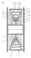
- the damper consists of an outer damper housing 1, with a lower base plate 2 and a preferably cylindrical circumferential wall 3, and a damper ram 4 protruding into the damper housing 1 from above, which is attached to a cover plate 5.
- An essentially central annular disk 6 is connected to the damper plunger 4 and is surrounded by an upper and a lower group, each of a plurality of annular disks.
- the upper group of disks comprises a flat washer 7 and two washers 8 and 9, which are provided on their outer peripheral edge with a driver in the form of an annular flange 10 and 15, respectively.
- an annular disk 11 which is attached to the upper edge of the peripheral wall 3.
- the lower group of disks comprises a flat washer 12, two washers 13 and 14, which are equipped with an annular flange 10 and 15, and finally an washer 16, which is arranged on the bottom region of the peripheral wall 3.
- the base plate 2 serves as a fastening means or fixed point.
- the damper housing 1 is filled with viscous damping medium.
- the damper plunger 4 is connected to a vibrating object (not shown) via the cover plate 5.
- the washers 7, 8 and 9 of the upper disk group and the washers 12, 13 and 14 of the lower disk group can be moved freely.
- the washers 8 and 9 and 13 and 14 each have such a diameter that two washers 8 and 9 or 13 and 14 are arranged in a plate-like manner.
- the ring flanges 10 and 15 of the ring disks 8, 9 and 13, 14 have the task of a driver.
- the distance between the damper plunger 4 and the peripheral wall 3 is divided into smaller displacements of the individual ring disks.
- all the ring disks move simultaneously so that the total path corresponds to the relative path between the damper ram 4 and the peripheral wall 3.
- very low-viscosity damping media there is a telescopic movement.
- the forces can reach similar orders of magnitude if the damper plunger 4 is moved in the vertical direction. These forces are mainly generated by the displacement of the damping medium between the washers 6, 7, 8, 9 and 11. In contrast to horizontal movement, the vertical movement is restricted by the special design. When the damper plunger 4 moves downward, the lowest point is reached when the ring disks 6 and 12, 12 and 13, 13 and 14 and 14 and 16 lie in pairs. The same applies to the upward movement of the damper plunger 4.
- each ring flange 10 or 15 of the movable ring disks 8, 9 or 13, 14 must be such that it is longer than the distance between the facing surfaces of the ring disks 11 and 16 fixed on the peripheral wall 3 reduced by the axial Thicknesses of all the ring disks located between the ring disks 11 and 16, i.e. the ring disks 6, 7, 8, 9 and 12, 13, 14.
- Such a dimensioning of the axial extent of the ring flanges 10 and 15 ensures permanent coupling of all the ring disks and a disintegration of the for example, the disc group consisting of the ring discs 6, 7, 8 and 9 or the group consisting of the ring discs 6, 12, 13, 14 prevented.
- the formation of an oblique position of the individual ring disks is prevented, which could lead to jamming, as a result of which, in the opposite direction, movement of the ring disks would be prevented.
- the embodiment according to FIG. 1 can be modified such that the annular disk 6 is not fixedly arranged on the damper ram 4, but maintains a radial distance from the damper ram 4 or is arranged with radial play to the damper ram 4.
- the difference compared to the embodiment of FIG. 1 is then that the washer 6 is vertically displaceably connected to the damper ram 4.
- This enables much larger vertical movements; however, the damping force is considerably lower than in the embodiment shown in FIG. 1. It is then practically achieved only by shearing the damping medium between the damper plunger 4 and the inner surfaces of the annular disks 6, 7, 8, 9 and 11 or 6, 12, 13, 14 and 16. If the damper plunger 4 is closed at its lower end, an additional displacement component in the vertical direction or a shear component during horizontal movement can be generated.
- This variant is particularly suitable for use in connection with earthquake protection systems, where the vertical movements usually do not require any noteworthy damping.
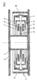
- Fig. 2 shows an embodiment which differs from that of Fig. 1 primarily in that the washers 11 and 16 are omitted. This embodiment is therefore very easy to manufacture.
- a bellows-shaped sleeve 40 is provided on the outer circumference of the two disk groups in such a way that both can only move apart from one another by a predetermined distance in the axial direction.
- the sleeve 40 is thus fastened to the uppermost and to the lowermost ring disks 9 and 14 and prevents these two disks from moving too far apart.
- the vertical damping effect in the embodiment according to FIG. 2 mainly results from the displacement of the damping medium.
- the vertical damping path is considerably larger than in the damper according to FIG. 1.
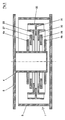
- each annular disk 6a, 6b is arranged at an axial distance from one another.
- two groups of several washers are provided.
- Each group comprises a flat washer 27 and 28, respectively, an washer 29 and 30, each with an outer ring flange, and finally a central washer 31, which belongs to both groups and is equipped with a double ring flange 32, which extends axially from the outer edge of the washer 31 Direction protrudes on opposite sides.
- the embodiment according to FIG. 3 is particularly suitable for large, vertically acting damping forces, namely for large movements. Since there are no annular disks 11 or 16 according to FIG. 1 in this embodiment, larger vertical movements are possible. With suitable dimensions, practically any vertical movements are possible, which are associated with a damping force that is generated mainly by the displacement of the damping medium on the upper and lower surfaces of the disk groups. In the horizontal direction, the procedure described above is obtained. While maintaining the damping effect in the vertical direction, the damping force for horizontal movements can be increased as desired if a plurality of disk packs consisting of annular disks 27, 29, 31, 30, 28 are provided. For each additional package, only one additional ring disk 6a or 6b may then be required.
- annular disc 6 is fixedly arranged on the damper ram 4, which is therefore movable both vertically and horizontally with the damper ram 4.
- this washer 6 is followed by a first further washer 7 and a further washer 8, each further washer having an outside diameter larger than the latter and an inside diameter smaller than the outside diameter of the latter with respect to the preceding ring disk.
- additional ring disks 8a and 7a follow, the same diameter ratios as just stated apply to these and their preceding ring disks.
- the smallest of the additional washers namely the washer 7a
- the washer 7a is not fixedly arranged on the damper plunger 4, but is associated with it with slight radial play.
- Such a radial play is otherwise provided on the outside of the annular disc 8 opposite the peripheral wall 3.
- the two radial games mentioned serve to move the damper plunger 4 together with the ring disks mentioned above in the vertical direction.
- a displacement of the damper plunger 4 from the right end position shown in FIG. 4 to the left causes the annular disks 6 and 7a to be displaced relative to the annular disks 7 and 8a or to the annular disk 8. This displacement is quasi a telescopic displacement.
- the damper can be equipped with a plurality of “large groups” of ring disks as described above, as can also be seen from FIG. 4.
- the smallest additional ring disk 7a of a first "large group” also forms the smallest further ring disk of the next "large group”;
- it therefore represents an equivalent to the washer 6 of the first "large group”, but without being fixed to the damper ram 4 at the same time.
- This embodiment is characterized by a particularly low overall height with regard to a disproportionately large damping effect in the vertical direction, while at the same time allowing relatively very large horizontal movements.
- the annular disk 6 can be arranged on the damper ram 4 with radial play, to achieve a specific damping characteristic.
- the disk groups shown in each case several times one above the other and equipping them with any number of ring disks in order to be able to realize greater damping forces.
- All embodiments are such a particularly compact construction, especially with a low overall height.
Landscapes
- Engineering & Computer Science (AREA)
- Architecture (AREA)
- General Engineering & Computer Science (AREA)
- Environmental & Geological Engineering (AREA)
- Business, Economics & Management (AREA)
- Emergency Management (AREA)
- Mechanical Engineering (AREA)
- Civil Engineering (AREA)
- Structural Engineering (AREA)
- Buildings Adapted To Withstand Abnormal External Influences (AREA)
- Vibration Prevention Devices (AREA)
- Fluid-Damping Devices (AREA)
- Details Of Measuring And Other Instruments (AREA)
Claims (15)
- Amortisseur de vibrations à action horizontale et verticale, comportant un carter d'amortisseur à paroi périphérique de préférence cylindrique, qui est fixée sur une plaque de base, un piston d'amortisseur pénétrant dans le carter d'amortisseur et auquel est associé, transversalement à l'axe longitudinal, au moins un disque annulaire, d'autres éléments de disque, ainsi qu'un fluide visqueux, caractérisé en ce que dans la direction axiale du piston d'amortisseur (4), au-dessus dudit au moins un disque annulaire (6; 6b), sont disposés de manière librement mobiles, des disques annulaires supplémentaires (7, 8, 9 et 12, 13, 14; 27, 29 et 28, 30), le premier (7) des disques annulaires supplémentaires (7, 8) présentant un diamètre extérieur supérieur, et un diamètre intérieur inférieur au diamètre extérieur du disque annulaire (6; 6b) du piston d'amortisseur (4), et les mêmes rapports de diamètres étant valables pour chaque disque annulaire supplémentaire suivant (8) par rapport au disque annulaire supplémentaire précédent (7).
- Amortisseur selon la revendication 1, caractérisé en ce qu'au moins sur quelques uns des disques annulaires supplémentaires, est formé sur le bord extérieur, un entraîneur (10, 15; 32), au moyen duquel le mouvement horizontal ou radial, des disques annulaires peut être transmis aux disques annulaires voisins, après dépassement d'un déplacement prédéterminé.
- Amortisseur selon la revendication 2, caractérisé en ce que l'entraîneur est réalisé sous la forme d'un flasque annulaire axial (10, 15; 32).
- Amortisseur selon la revendication 2 ou 3, caractérisé en ce que les disques annulaires (8, 9 et 13, 14) comportant des flasques annulaires (10, 15), présentent des diamètres différents et peuvent être insérés l'un dans l'autre à la manière de coupelles.
- Amortisseur selon l'une au moins des revendications 2 à 4, caractérisé en ce que sur le piston d'amortisseur (4) est disposé, notamment fixé, un seul disque annulaire (6), et respectivement au-dessus et en-dessous de celui-ci est disposé un groupe de disques annulaires supplémentaires (7, 8, 9 et 12, 13, 14), et en ce que vu du disque annulaire (6) du piston d'amortisseur (4), à partir du second disque annulaire supplémentaire (8, 9; 13, 14), est prévu sur ceux-ci, un flasque annulaire (10, 15), et les flasques annulaires (10, 15) des deux groupes de disques annulaires sont d'orientation axiale opposée, en se référant à leurs disques annulaires.
- Amortisseur selon la revendication 5, caractérisé en ce que le disque annulaire supérieur (9) de diamètre le plus grand, du groupe supérieur de disques annulaires, et le disque annulaire inférieur (14) de diamètre le plus grand du groupe inférieur de disques annulaires, sont reliés l'un à l'autre par l'intermédiaire d'un fourreau (40) en forme de soufflet.
- Amortisseur selon la revendication 5 ou 6, caractérisé en ce qu'au-dessus du groupe supérieur de disques et en-dessous du groupe inférieur, est prévu un flasque annulaire (11 respectivement 16), qui est relié de manière fixe à la paroi périphérique (3), et qui limite les mouvements verticaux des groupes de disques annulaires et du piston d'amortisseur (4).
- Amortisseur selon la revendication 5, caractérisé en ce que sur le piston d'amortisseur (4) sont disposés, notamment fixés, deux disques annulaires (6a, 6b) espacés axialement, et deux groupes de disques annulaires supplémentaires (27, 29, 31; 28, 30, 31) sont disposés entre les deux disques annulaires (6a, 6b) du piston d'amortisseur (4).
- Amortisseur selon la revendication 8, caractérisé en ce que le disque annulaire supplémentaire (31) le plus grand, fait partie des deux groupes de disques annulaires, et est équipé sur son bord extérieur, d'un flasque annulaire (32) dirigé vers le haut et vers le bas.
- Amortisseur selon la revendication 1, caractérisé en ce qu'au disque annulaire (6) associé au piston d'amortisseur (4), succèdent au moins deux disques annulaires supplémentaires (7, 8) présentant les rapports de diamètres évoqués.
- Amortisseur selon la revendication 10, caractérisé en ce qu'aux-dits au moins deux disques annulaires supplémentaires (7, 8) succèdent un nombre identique de disques annulaires auxiliaires (8a, 7a), le premier (8a) des disques annulaires auxiliaires (8a, 7a) présentant un diamètre extérieur supérieur et un diamètre intérieur inférieur au diamètre intérieur du plus grand (8) des disques annulaires supplémentaires (7, 8), et les mêmes rapports de diamètres étant valables pour chaque disque annulaire auxiliaire suivant (7a) par rapport au disque annulaire auxiliaire précédent (8a), le disque annulaire auxiliaire (7a) le plus petit étant associé de manière libre au piston d'amortisseur (4).
- Amortisseur selon la revendication 11, caractérisé en ce qu'au groupe de disques annulaires composé du disque annulaire (6) du piston d'amortisseur (4), des disques annulaires supplémentaires (7, 8) et des disques annulaires auxiliaires (8a, 7a), succède au moins un autre tel groupe de disques annulaires, dont les deux plus petits disques annulaires sont associés de manière libre au piston d'amortisseur (4).
- Amortisseur selon la revendication 12, caractérisé en ce que le disque annulaire le plus petit de chaque autre groupe de disques annulaires, voisin du groupe de disques annulaires respectivement précédent, est un disque annulaire des deux groupes de disques annulaires.
- Amortisseur selon l'une au moins des revendications précédentes, caractérisé en ce que le piston d'amortisseur (4) est réalisé sous la forme d'un tube cylindrique.
- Amortisseur selon la revendication 14, caractérisé en ce que le piston d'amortisseur (4) est fermé à son extrémité libre.
Applications Claiming Priority (2)
| Application Number | Priority Date | Filing Date | Title |
|---|---|---|---|
| DE4206097 | 1992-02-27 | ||
| DE4206097A DE4206097A1 (de) | 1992-02-27 | 1992-02-27 | Horizontal und vertikal wirkender viskoser schwingungsdaempfer |
Publications (2)
| Publication Number | Publication Date |
|---|---|
| EP0557947A1 EP0557947A1 (fr) | 1993-09-01 |
| EP0557947B1 true EP0557947B1 (fr) | 1995-07-19 |
Family
ID=6452759
Family Applications (1)
| Application Number | Title | Priority Date | Filing Date |
|---|---|---|---|
| EP93102842A Expired - Lifetime EP0557947B1 (fr) | 1992-02-27 | 1993-02-23 | Amortisseur de vibrations visqueux à action horizontale et verticale |
Country Status (4)
| Country | Link |
|---|---|
| US (1) | US5373920A (fr) |
| EP (1) | EP0557947B1 (fr) |
| JP (1) | JP2811524B2 (fr) |
| DE (2) | DE4206097A1 (fr) |
Families Citing this family (11)
| Publication number | Priority date | Publication date | Assignee | Title |
|---|---|---|---|---|
| DE19626548A1 (de) * | 1996-07-02 | 1998-01-08 | Hottinger Messtechnik Baldwin | Hydraulisches Dämpfungselement |
| FR2754579B1 (fr) * | 1996-10-15 | 1998-12-11 | Hutchinson | Amortisseur de vibrations, notamment pour rotor d'helicoptere |
| DE19715714A1 (de) * | 1997-04-15 | 1998-10-22 | Maurer Friedrich Soehne | Dämpferelement und damit versehene Dämpfungseinheit |
| JP4038266B2 (ja) * | 1998-02-17 | 2008-01-23 | オイレス工業株式会社 | 粘性せん断型ダンパー |
| US6641121B1 (en) | 2002-01-03 | 2003-11-04 | Meritor Light Vehicle Technology, Llc | Damping structure |
| US6722677B2 (en) | 2002-01-04 | 2004-04-20 | Meritor Light Vehicle Technology, Llc | Connecting component |
| RU2236618C1 (ru) * | 2003-03-17 | 2004-09-20 | Ткачев Виктор Петрович | Энергопоглощающее устройство |
| FR2866402B1 (fr) * | 2004-02-13 | 2008-01-25 | Bosch Gmbh Robert | Amortisseur de vibrations pour freins a disques. |
| DE102006058940B4 (de) * | 2006-12-12 | 2008-10-02 | Voith Patent Gmbh | Verfahren und Vorrichtung zur Dämpfung von Schwingungen |
| DE102008015106A1 (de) * | 2008-03-19 | 2009-09-24 | Franz Prof. Dr. med. Copf sen. | Dämpfungsvorrichtung |
| US12446141B2 (en) | 2020-05-06 | 2025-10-14 | Asml Netherlands B.V. | Contamination shield for mechanically insulating device |
Family Cites Families (19)
| Publication number | Priority date | Publication date | Assignee | Title |
|---|---|---|---|---|
| DE701817C (de) * | 1937-10-15 | 1941-01-24 | Siemens Schuckertwerke Akt Ges | Daempfungseinrichtung |
| US2661915A (en) * | 1949-06-04 | 1953-12-08 | Houdaille Hershey Corp | Aircraft landing wheel shimmy damper |
| FR1092543A (fr) * | 1953-10-29 | 1955-04-22 | Amortisseur d'oscillations hydrauliques à pistons multiples | |
| US3368807A (en) * | 1966-01-19 | 1968-02-13 | Litton Systems Inc | Vibration isolator |
| JPS5319655A (en) * | 1976-08-09 | 1978-02-23 | Kajima Corp | Earthquake proofing construction work |
| JPS5319657A (en) * | 1976-08-09 | 1978-02-23 | Kajima Corp | Framework exempted from earthquake |
| SU775234A1 (ru) * | 1978-11-09 | 1980-10-30 | Фрунзенский политехнический институт | Антисейсмическа опора |
| DE3017321C3 (de) * | 1980-05-06 | 1994-08-04 | Samson Ag | Dämpfungsvorrichtung für Meß- oder Regelgeräte |
| SU1043385A1 (ru) * | 1981-01-09 | 1983-09-23 | Харьковский Ордена Ленина Политехнический Институт Им.В.И.Ленина | Амортизатор |
| US4554767A (en) * | 1981-02-05 | 1985-11-26 | Ikonomou Aristarchos S | Earthquake guarding system |
| DE3314203A1 (de) * | 1983-04-21 | 1984-10-25 | Gerb Gesellschaft für Isolierung mbH & Co KG, 1000 Berlin | Beheizbarer viskoser daempfer |
| JPS59205035A (ja) * | 1983-05-09 | 1984-11-20 | Chiyoda Chem Eng & Constr Co Ltd | 構造物架台用粘性ダンパ− |
| DE3424338A1 (de) * | 1984-06-27 | 1986-01-09 | Gerb Gesellschaft für Isolierung mbH & Co KG, 1000 Berlin | Viskoser daempfer mit konischem stempelrohr |
| DE3431657A1 (de) * | 1984-08-29 | 1986-03-13 | Roswitha 4300 Essen Klüsener | Vorrichtung zur sicherung von gebaeudekonstruktionen gegen dynamische belastungen |
| JPS6299570A (ja) * | 1985-10-28 | 1987-05-09 | 千代田化工建設株式会社 | 非線形ダンパ− |
| FI905506A0 (fi) * | 1989-03-07 | 1990-11-06 | N Proizv Ob Proekt I I Energet | Viskoelastisk daempare. |
| JPH02245531A (ja) * | 1989-03-20 | 1990-10-01 | Tokico Ltd | 粘性ダンパ |
| JP2799024B2 (ja) * | 1990-01-20 | 1998-09-17 | トキコ株式会社 | 粘性ダンパ |
| DE4023930A1 (de) * | 1990-07-27 | 1992-02-06 | Wacker Chemie Gmbh | Viskoelastischer schwingungsdaempfer |
-
1992
- 1992-02-27 DE DE4206097A patent/DE4206097A1/de not_active Withdrawn
-
1993
- 1993-02-23 EP EP93102842A patent/EP0557947B1/fr not_active Expired - Lifetime
- 1993-02-23 DE DE59300359T patent/DE59300359D1/de not_active Expired - Fee Related
- 1993-02-25 US US08/022,977 patent/US5373920A/en not_active Expired - Fee Related
- 1993-02-26 JP JP5062909A patent/JP2811524B2/ja not_active Expired - Fee Related
Also Published As
| Publication number | Publication date |
|---|---|
| JP2811524B2 (ja) | 1998-10-15 |
| US5373920A (en) | 1994-12-20 |
| EP0557947A1 (fr) | 1993-09-01 |
| DE4206097A1 (de) | 1993-09-02 |
| JPH06123324A (ja) | 1994-05-06 |
| DE59300359D1 (de) | 1995-08-24 |
Similar Documents
| Publication | Publication Date | Title |
|---|---|---|
| DE69400974T2 (de) | Stossverzehrelement mit stetigem Verformungswiderstand | |
| CH666427A5 (de) | Metallspritz-giessform. | |
| EP0556629B1 (fr) | Amortisseur de vibrations visqueux à action horizontale et verticale | |
| EP0557947B1 (fr) | Amortisseur de vibrations visqueux à action horizontale et verticale | |
| DE10143778B4 (de) | Vibrationsdämpfungsvorrichtung für ein Fahrzeug | |
| DE2528628C2 (fr) | ||
| DE69201088T2 (de) | Stossdämpfer mit beschränktem-Durchflusssystem. | |
| EP0651371B1 (fr) | Amortisseur de vibration pour atténuer le son structurel | |
| DE2825524A1 (de) | Stossdaempfer | |
| EP2218938A1 (fr) | Dispositif d'amortissement, notamment pour un degré d'oscillation de deux masses | |
| DE102007006087A1 (de) | Einstellbare Stützvorrichtung auf Basis der Elemente Innendoppelkeil, Außendoppelkeil wahlweise Rollensystem und Stellschraube mit Links- und Rechtsgewinde | |
| EP2032871A2 (fr) | Élément d'amortissement | |
| DE3827125A1 (de) | Stroemungsmittelgefuellte elastische montageeinheit | |
| DE4204128A1 (de) | Horizontal und vertikal wirkender viskoser schwingungsdaempfer | |
| AT521299B1 (de) | Verfahren zur pulvermetallurgischen Herstellung eines Kugelrampenelementes | |
| DE19723515C2 (de) | Elastische Anordnung zum Führen von zwei elastisch verbundenen Bauteilen in einer Bewegungsrichtung | |
| DE10214417C1 (de) | Passiver Schwingungstilger | |
| EP0555790B1 (fr) | Amortisseur de vibrations visqueux à action horizontale et verticale | |
| DE1932784C3 (de) | Gewölbte Federplatte für Verdichterventile | |
| DE3012550C2 (de) | Flüssigkeitsgekühlter Transformator für große Leistungen | |
| DE3501415A1 (de) | Kupplungsvorrichtung mit flexiblen lamellen | |
| EP0099559A2 (fr) | Dispositif de retardement hydraulique | |
| EP3976990B1 (fr) | Amortisseur d'impulsion pour constructions et installations minces et hautes | |
| DE2433185C2 (de) | Stoß- bzw. Schwingungsdämpfer | |
| DE102009002525A1 (de) | Schwingungsdämpfer |
Legal Events
| Date | Code | Title | Description |
|---|---|---|---|
| PUAI | Public reference made under article 153(3) epc to a published international application that has entered the european phase |
Free format text: ORIGINAL CODE: 0009012 |
|
| AK | Designated contracting states |
Kind code of ref document: A1 Designated state(s): DE FR GB |
|
| 17P | Request for examination filed |
Effective date: 19931004 |
|
| 17Q | First examination report despatched |
Effective date: 19941115 |
|
| GRAA | (expected) grant |
Free format text: ORIGINAL CODE: 0009210 |
|
| AK | Designated contracting states |
Kind code of ref document: B1 Designated state(s): DE FR GB |
|
| REF | Corresponds to: |
Ref document number: 59300359 Country of ref document: DE Date of ref document: 19950824 |
|
| GBT | Gb: translation of ep patent filed (gb section 77(6)(a)/1977) |
Effective date: 19950814 |
|
| ET | Fr: translation filed | ||
| PLBE | No opposition filed within time limit |
Free format text: ORIGINAL CODE: 0009261 |
|
| STAA | Information on the status of an ep patent application or granted ep patent |
Free format text: STATUS: NO OPPOSITION FILED WITHIN TIME LIMIT |
|
| 26N | No opposition filed | ||
| PGFP | Annual fee paid to national office [announced via postgrant information from national office to epo] |
Ref country code: FR Payment date: 19990225 Year of fee payment: 7 |
|
| PGFP | Annual fee paid to national office [announced via postgrant information from national office to epo] |
Ref country code: GB Payment date: 20000127 Year of fee payment: 8 |
|
| PGFP | Annual fee paid to national office [announced via postgrant information from national office to epo] |
Ref country code: DE Payment date: 20000228 Year of fee payment: 8 |
|
| PG25 | Lapsed in a contracting state [announced via postgrant information from national office to epo] |
Ref country code: FR Free format text: LAPSE BECAUSE OF NON-PAYMENT OF DUE FEES Effective date: 20001031 |
|
| REG | Reference to a national code |
Ref country code: FR Ref legal event code: ST |
|
| PG25 | Lapsed in a contracting state [announced via postgrant information from national office to epo] |
Ref country code: GB Free format text: LAPSE BECAUSE OF NON-PAYMENT OF DUE FEES Effective date: 20010223 |
|
| GBPC | Gb: european patent ceased through non-payment of renewal fee |
Effective date: 20010223 |
|
| PG25 | Lapsed in a contracting state [announced via postgrant information from national office to epo] |
Ref country code: DE Free format text: LAPSE BECAUSE OF NON-PAYMENT OF DUE FEES Effective date: 20011201 |