EP0559080B1 - Dispositif pour évacuer une composante de gaz - Google Patents
Dispositif pour évacuer une composante de gaz Download PDFInfo
- Publication number
- EP0559080B1 EP0559080B1 EP93102950A EP93102950A EP0559080B1 EP 0559080 B1 EP0559080 B1 EP 0559080B1 EP 93102950 A EP93102950 A EP 93102950A EP 93102950 A EP93102950 A EP 93102950A EP 0559080 B1 EP0559080 B1 EP 0559080B1
- Authority
- EP
- European Patent Office
- Prior art keywords
- opening
- fan
- partition
- radial fan
- guide surface
- Prior art date
- Legal status (The legal status is an assumption and is not a legal conclusion. Google has not performed a legal analysis and makes no representation as to the accuracy of the status listed.)
- Expired - Lifetime
Links
- 238000010411 cooking Methods 0.000 claims abstract description 22
- 238000005192 partition Methods 0.000 claims abstract description 19
- 238000007599 discharging Methods 0.000 claims 2
- 239000007789 gas Substances 0.000 description 23
- 241000446313 Lamella Species 0.000 description 2
- 238000000034 method Methods 0.000 description 2
- XLYOFNOQVPJJNP-UHFFFAOYSA-N water Substances O XLYOFNOQVPJJNP-UHFFFAOYSA-N 0.000 description 2
- 230000015572 biosynthetic process Effects 0.000 description 1
- 239000012141 concentrate Substances 0.000 description 1
- 239000003517 fume Substances 0.000 description 1
- 230000005484 gravity Effects 0.000 description 1
- 238000010438 heat treatment Methods 0.000 description 1
- 239000002244 precipitate Substances 0.000 description 1
Images

Classifications
-
- F—MECHANICAL ENGINEERING; LIGHTING; HEATING; WEAPONS; BLASTING
- F24—HEATING; RANGES; VENTILATING
- F24C—DOMESTIC STOVES OR RANGES ; DETAILS OF DOMESTIC STOVES OR RANGES, OF GENERAL APPLICATION
- F24C15/00—Details
- F24C15/20—Removing cooking fumes
-
- F—MECHANICAL ENGINEERING; LIGHTING; HEATING; WEAPONS; BLASTING
- F04—POSITIVE - DISPLACEMENT MACHINES FOR LIQUIDS; PUMPS FOR LIQUIDS OR ELASTIC FLUIDS
- F04D—NON-POSITIVE-DISPLACEMENT PUMPS
- F04D29/00—Details, component parts, or accessories
- F04D29/70—Suction grids; Strainers; Dust separation; Cleaning
- F04D29/701—Suction grids; Strainers; Dust separation; Cleaning especially adapted for elastic fluid pumps
- F04D29/703—Suction grids; Strainers; Dust separation; Cleaning especially adapted for elastic fluid pumps specially for fans, e.g. fan guards
Definitions
- the invention relates to a device according to the preamble of patent claim 1.
- an extractor hood for kitchens is known in which an essentially radially directed flow is generated in the gas volume present in the extractor hood.
- the radial fan is included partially surrounded by a guide surface, a housing wall being provided, onto which the gas flow in the extractor hood is directed by means of a partition serving as a guide surface.
- a single gas component, such as moisture or the like, which is present in excess, from the gas volume is not possible with this device.
- a device for removing a gas component from a cooking chamber has a radial fan, which is arranged in the vicinity of the substantially flat housing wall.
- a housing opening for removing the gas component and a partition for deflecting the gas flow generated by the radial fan onto the housing opening are provided near the circumference of the fan wheel.
- a single gas component, such as moisture and the like, which is present in excess from the gas volume, is also not possible with this device.
- the invention has for its object to provide a device of the aforementioned type, by means of which a certain gas component, in particular moisture, can be partially removed from the cooking space of a cooking appliance.
- the housing wall is arranged essentially vertically and delimits a cooking space of a cooking appliance; that the housing wall is penetrated by a drive shaft of a motor arranged on the side of the housing wall facing away from the radial fan, said motor carrying the fan wheel inside the cooking chamber; and that the partition is formed as only a part of the flow generated by the radial fan directed towards the housing opening aerodynamic guide surface and is arranged near the circumference of the fan wheel.
- the radial fan is at least partially surrounded by a guide surface which includes a discharge area adjacent to the housing opening.
- the guide surface is essentially circular is.
- the guide surface has the shape of a hollow truncated cone which widens towards the housing wall.
- the guide surface is arranged around the entire circumference of the blower, but at most partially overlapping the blower in the axial direction.
- the housing opening can be at least partially opened and / or closed depending on the content of the gas in the excess component.
- a further embodiment of the invention provides that at least one flap, a lamella closure, an iris-like closure or the like is provided for closing the housing opening.
- the flap is guided in rails.
- a stud is attached to the flap, which slides the flap in the shaft.
- a further embodiment of the invention provides that it has a shaft with an outlet which is inclined relative to a housing wall in which the housing opening is provided and into which the housing opening opens.
- the partition is arranged centrally with respect to the housing opening.
- the dividing wall is designed as a partial ring surface projecting from the substantially circular housing opening on the side radially outward with respect to the axis of rotation of the radial fan in the direction of the radial fan.
- Another embodiment is characterized in that the partition is essentially flat and extends in the radial direction of the radial fan.
- the partition is ploughshare-like, the share edge lying in a plane containing the axis of the radial fan and the share surfaces diverging with respect to the axis of rotation of the radial fan to the outside.
- the housing opening is at least partially swept by the radial fan.
- the fan produces a gas flow, possibly on the inside of the guide surface provided, which is directed in the direction of rotation.
- the direction of rotation of the fan can be changed at regular intervals, particularly when used in cooking appliances, so that the direction of the gas flow also changes accordingly.
- Two gas flows circulating on the guide surface are thus generated alternately.
- the gas is pressed onto a partition in the discharge area and can be discharged from the housing through a housing opening.
- control it can be provided that the housing opening can be at least partially opened depending on the content of the gas in the excess component and / or is closable.
- the control can be carried out, for example, using the method described in German patent application P 42 06 845.2-52 (published on September 9, 1993).
- the guide surface it is not necessary for the guide surface to be guided around the entire circumference of the fan, as long as it is only ensured that the flow develops with the desired properties.
- At least one flap, a lamella closure, an iris-like closure or the like can be provided to close the housing opening.
- the flap there is the possibility either to arrange it vertically or to provide that two flaps move towards or away from each other in the manner of a double-leaf sliding door.
- the discharge of the gas with the gas component to be removed takes place effectively if the device has a shaft with an outlet which is inclined relative to the housing wall in which the housing opening is provided and into which the housing opening opens.
- the flap In order to be able to close the opening in a substantially gas-tight manner, the flap can be guided in appropriately designed rails.
- a cleat is also attached to the flap, which slides the flap in the shaft, it can also be achieved that, for example, by the cleat's own elasticity or one additionally on the cleat provided spring, a pressure of the flap is exerted on the opening area.
- the partition is arranged centrally with respect to the housing opening.
- an essential feature of the inventive concept is that even if no guide surface surrounding the radial fan is provided, a gas flow can be directed towards the housing opening to the desired extent by means of the partition serving as an aerodynamic guide surface, so that for example, moisture can be removed from the cooking space atmosphere or the like with the separated gas volume as required.
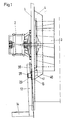
- a motor 2 is attached to a housing wall 1, the shaft of which through the housing wall 1 into the interior of the housing, not shown here, with a fan wheel 3 attached to this shaft.
- a fan surface 4 is provided concentrically surrounding the fan wheel 3, which partially closes with the housing wall 1 in the exemplary embodiment shown here.
- a discharge area 40 is provided in the lower area of the guide surface 4, which is opposite a housing opening 10 in the housing wall 1.
- the housing opening 10 can be closed by means of a flap 20 which can be moved via a lever mechanism, of which only one bracket 30 is shown here.
- Communicated with the housing opening 10, a shaft 12 is arranged, which is inclined slightly inwards relative to the housing wall 1 in the direction of the housing.
- the flap 20 runs on a shaft wall, sliding through a stud 28.
- the shaft 12 opens into an outlet 14. This is arranged essentially perpendicular to the shaft 12, so that moisture which condenses in the shaft 12 can run off due to gravity.
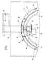
- Fig. 2 shows a second embodiment of a device according to the present invention in detail.
- the guide surface 4 is designed here so that it only surrounds the fan wheel 3 in a lower region. Otherwise, the structure corresponds to that of FIG. 1.
- a spring 29 provided on the stud 28 attached to the flap 20 ensures that the flap 20 is pressed onto the opening 10.
- the guide surface 4 has on its side facing the center of the arrangement a folded fold 44, which further concentrates the gas flow on the inside of the guide surface 4 causes.
- a partition 42 is arranged on the guide surface 4 in a substantially vertical direction.
- the flow generated by the fan wheel, not shown in FIG. 3, which propagates along the guide surface 4 is diverted at the partition 42 and guided in the direction of the housing opening 10.
- the guide surface 4 is fastened to the housing wall with flanges 46, 48, and fastening options can also be provided in the discharge area 40.
- 4 heating coils 5, 6 are arranged outside the guide surface.
- the flap 20 is connected to a bracket 30 of a lever mechanism, which is also connected to a linkage and additional required mechanism 36 via a pivot point 32.
- the entire control system both mechanical and electronic, can thus be arranged outside the housing in which the gas volume is located.
- a sliding aid 22 for the flap 20 is provided in the upper region of the shaft 12.
- the flap 20 itself runs trapezoidal. By means of the mechanics, it can be placed more or less far into the shaft 12, guided in rails 24, 26, the housing opening 10 being opened more or less in accordance with the specified specifications. Since the shaft 12 is generally at a lower temperature than the heated interior of the housing, the moisture precipitates in the shaft and runs into the outlet 14, from where it can be drained through an opening 16.
- the mechanism for lifting and lowering the flap 20 must be designed so that it ensures the trouble-free functioning of the device. However, there is no need for the limitation shown in FIG. 3.
- This device is preferably used to control the moisture content of a cooking chamber atmosphere. As soon as an excessively high moisture content is determined, the flap 20 is opened, the pressure built up by the guide surface 4 ensuring that the cooking chamber atmosphere is forced away. Dry air flowing in lowers the moisture content inside the cooking space. If the moisture content should remain constant or even be increased, the flap 20 is closed. If necessary, measures can be provided which make it possible to supply moisture specifically to the interior of the cooking space.
Landscapes
- Engineering & Computer Science (AREA)
- Mechanical Engineering (AREA)
- General Engineering & Computer Science (AREA)
- Chemical & Material Sciences (AREA)
- Combustion & Propulsion (AREA)
- Structures Of Non-Positive Displacement Pumps (AREA)
- Other Investigation Or Analysis Of Materials By Electrical Means (AREA)
- Ventilation (AREA)
- Glass Compositions (AREA)
- Sampling And Sample Adjustment (AREA)
Claims (15)
- Dispositif d'évacuation d'un constituant gazeux de l'atmosphère d'un espace de cuisson, comportant une soufflante radiale présentant une roue de ventilation (3), disposée à proximité d'une paroi d'enveloppe (1) sensiblement plane, une ouverture (10), prévue dans la paroi d'enveloppe (1) à proximité de la périphérie de la roue de ventilation (3) pour l'évacuation du constituant gazeux, et une paroi de séparation (42) pour renvoyer, vers l'ouverture d'enveloppe (10), l'écoulement gazeux produit par la soufflante radiale, caractérisé en ce que la paroi d'enveloppe (1) est située sensiblement verticalement et délimite un espace de cuisson d'un appareil de cuisson ; en ce que la paroi d'enveloppe (1) est traversée par un arbre de commande d'un moteur (2), placé à l'extérieur de l'espace de cuisson, sur le côté de la paroi d'enveloppe (1) orienté à l'opposé de la soufflante radiale, cet arbre portant la roue de ventilation (3) à l'intérieur de l'espace de cuisson ; et en ce que la paroi de séparation (42) est réalisée simplement en tant qu'élément de la surface aérodynamique dirigeant vers l'ouverture d'enveloppe (10) l'écoulement produit par la soufflante radiale, et en ce qu'elle est disposée à proximité de la périphérie de la roue de ventilation (3).
- Dispositif selon la revendication 1, caractérisé en ce que la soufflante radiale (3) est entourée, du moins en partie, par une surface de guidage (4), qui comprend une zone de déflexion (40) adjacente à l'ouverture d'enveloppe (10).
- Dispositif selon la revendication 2, caractérisé en ce que la surface de guidage (4) est sensiblement en forme d'anneau de cercle.
- Dispositif selon la revendication 2, caractérisé en ce que la surface de guidage (4) a la forme d'un cône tronqué creux, qui s'évase en direction de la paroi d'enveloppe (1).
- Dispositif selon l'une des revendications 2 à 4, caractérisé en ce que la surface de guidage (4) est disposée autour de toute la périphérie de la soufflante (3), toutefois en ne recouvrant la soufflante (3) au maximum qu'en partie dans le sens axial.
- Dispositif selon l'une des revendications précédentes, caractérisé en ce que l'ouverture d'enveloppe (10) peut être ouverte et/ou fermée au moins partiellement, en fonction de la teneur du gaz en constituant surabondant.
- Dispositif selon la revendication 6, caractérisé en ce qu'il est prévu, pour obturer l'ouverture d'enveloppe (10), au moins une trappe (20), un obturateur à lamelles, un obturateur du type diaphragme à iris, ou analogues.
- Dispositif selon la revendication 7, caractérisé en ce que la trappe (20) est guidée dans des rails (24, 26).
- Dispositif selon la revendication 7 ou 8, caractérisé en ce qu'une pièce saillante (28) est fixée contre la trappe (20) afin de guider la trappe (20) dans la cheminée (12) par glissement.
- Dispositif selon l'une des revendications précédentes, caractérisé en ce qu'il présente une cheminée (12) avec évacuation (14), inclinée par rapport à une paroi d'enveloppe (1), dans laquelle est prévue l'ouverture d'enveloppe (10), et dans laquelle débouche l'ouverture d'enveloppe (10).
- Dispositif selon l'une des revendications précédentes, caractérisé en ce que la paroi de séparation (42) est disposée de manière centrale par rapport à l'ouverture d'enveloppe (10).
- Dispositif selon l'une des revendications précédentes, caractérisé en ce que la paroi de séparation (42) est réalisée sous la forme d'une surface annulaire partielle, en saillie à partir de l'ouverture d'enveloppe (10) sensiblement circulaire au niveau du côté situé radialement à l'extérieur par rapport à l'axe de rotation de la soufflante radiale (3), en direction de la soufflante radiale (3).
- Dispositif selon l'une des revendications 1 à 11, caractérisé en ce que la paroi de séparation (42) est réalisée sensiblement plane et en ce qu'elle s'étend dans le sens radial de la soufflante radiale (3).
- Dispositif selon l'une des revendications 1 à 11, caractérisé en ce que la paroi de séparation (42) est réalisée en forme de soc de charrue, l'arête du soc étant située dans un plan contenant l'axe de la soufflante radiale (3) et les faces du soc s'étendant en divergeant vers l'extérieur par rapport à l'axe de rotation de la soufflante radiale (3).
- Dispositif selon l'une des revendications précédentes, caractérisé en ce que l'ouverture d'enveloppe (10) est balayée, du moins partiellement, par la soufflante radiale (3).
Priority Applications (2)
| Application Number | Priority Date | Filing Date | Title |
|---|---|---|---|
| US08/025,999 US5370498A (en) | 1992-03-04 | 1993-03-04 | Apparatus for elimination of gas constituents |
| JP04407393A JP3437597B2 (ja) | 1992-03-04 | 1993-03-04 | ガス成分除去装置 |
Applications Claiming Priority (2)
| Application Number | Priority Date | Filing Date | Title |
|---|---|---|---|
| DE4206847 | 1992-03-04 | ||
| DE4206847 | 1992-03-04 |
Publications (2)
| Publication Number | Publication Date |
|---|---|
| EP0559080A1 EP0559080A1 (fr) | 1993-09-08 |
| EP0559080B1 true EP0559080B1 (fr) | 1996-11-20 |
Family
ID=6453225
Family Applications (1)
| Application Number | Title | Priority Date | Filing Date |
|---|---|---|---|
| EP93102950A Expired - Lifetime EP0559080B1 (fr) | 1992-03-04 | 1993-02-25 | Dispositif pour évacuer une composante de gaz |
Country Status (6)
| Country | Link |
|---|---|
| EP (1) | EP0559080B1 (fr) |
| AT (1) | ATE145468T1 (fr) |
| DE (1) | DE59304500D1 (fr) |
| DK (1) | DK0559080T3 (fr) |
| ES (1) | ES2094392T3 (fr) |
| GR (1) | GR3021756T3 (fr) |
Families Citing this family (1)
| Publication number | Priority date | Publication date | Assignee | Title |
|---|---|---|---|---|
| EP0926449B2 (fr) * | 1997-12-23 | 2003-05-21 | eloma GmbH Grossküchentechnik | Procédé pour déshumidifier un espace à cuire d'un dispositif pour cuire à la vapeur et dispositif approprié |
Family Cites Families (2)
| Publication number | Priority date | Publication date | Assignee | Title |
|---|---|---|---|---|
| SE353142B (fr) * | 1970-01-30 | 1973-01-22 | N Bergmark | |
| IT1222139B (it) * | 1987-07-27 | 1990-09-05 | Elica Spa | Cappa di aspirazione fumi,particolarmente per cucine domestiche,a larga aerea di captazione |
-
1993
- 1993-02-25 EP EP93102950A patent/EP0559080B1/fr not_active Expired - Lifetime
- 1993-02-25 AT AT93102950T patent/ATE145468T1/de not_active IP Right Cessation
- 1993-02-25 DK DK93102950.8T patent/DK0559080T3/da active
- 1993-02-25 DE DE59304500T patent/DE59304500D1/de not_active Expired - Fee Related
- 1993-02-25 ES ES93102950T patent/ES2094392T3/es not_active Expired - Lifetime
-
1996
- 1996-11-21 GR GR960403079T patent/GR3021756T3/el unknown
Also Published As
| Publication number | Publication date |
|---|---|
| GR3021756T3 (en) | 1997-02-28 |
| DE59304500D1 (de) | 1997-01-02 |
| EP0559080A1 (fr) | 1993-09-08 |
| DK0559080T3 (da) | 1997-05-05 |
| ES2094392T3 (es) | 1997-01-16 |
| ATE145468T1 (de) | 1996-12-15 |
Similar Documents
| Publication | Publication Date | Title |
|---|---|---|
| EP0926449B2 (fr) | Procédé pour déshumidifier un espace à cuire d'un dispositif pour cuire à la vapeur et dispositif approprié | |
| EP2476960B1 (fr) | Dispositif de commutation pour une hotte aspirante destiné à commuter entre un fonctionnement à air ambiant et un fonctionnement à air d'évacuation | |
| EP3505830A1 (fr) | Dispositif formant hotte aspirante permettant d'aspirer les vapeurs de cuisson vers le bas | |
| DE2837543A1 (de) | Dunstabzugsvorrichtung | |
| EP0598211A1 (fr) | Four, en particulier four à nettoyage par pyrolyse | |
| EP3276265A1 (fr) | Appareil ménager | |
| DE69713561T2 (de) | Küchenventilator | |
| EP3686496B1 (fr) | Hotte aspirante et procédé de remplacement des unités de filtre | |
| DE2006621C2 (de) | Back- und Bratrohr | |
| EP2857758B1 (fr) | Dispositif d'aspiration de vapeur | |
| EP0559080B1 (fr) | Dispositif pour évacuer une composante de gaz | |
| DE4407702A1 (de) | Vorrichtung zum Abführen von Wrasen aus einem Backofen | |
| DE4445594A1 (de) | Back- und Bratofen mit einem Luftkanal | |
| EP0491166B1 (fr) | Hotte de laboratoire | |
| DE8912976U1 (de) | Backofentür | |
| DE4206846C2 (de) | Vorrichtung zum Abscheiden von Feststoff- und/oder Flüssigkeitspartikeln aus einem Gasvolumen | |
| BE1032517B1 (de) | Absaugvorrichtung für ein Kochfeld mit einer Kochfeldplatte und Kochfeld | |
| DE10207638B4 (de) | Heißluftofen mit verbesserter Türabdichtung | |
| DE3125110C2 (de) | Schüttgutbunker-Austragvorrichtung | |
| DE2323229A1 (de) | Ueberwachungseinrichtung fuer die filteranordnung in dunstabzugshauben u. dgl | |
| EP3202291B1 (fr) | Appareil de cuisson et dispositif d'écoulement associé | |
| DE4312825C1 (de) | Anordnung zur Luftzufuhr bei einem Radialgebläse oder dergleichen | |
| DE19825322A1 (de) | Backofen mit Strömungsleitmitteln | |
| DE3734408C2 (de) | Absaugvorrichtung | |
| DE3038216C2 (de) | Backofen mit Backwagen |
Legal Events
| Date | Code | Title | Description |
|---|---|---|---|
| PUAI | Public reference made under article 153(3) epc to a published international application that has entered the european phase |
Free format text: ORIGINAL CODE: 0009012 |
|
| AK | Designated contracting states |
Kind code of ref document: A1 Designated state(s): AT BE CH DE DK ES FR GB GR IE IT LI LU NL PT SE |
|
| 17P | Request for examination filed |
Effective date: 19940210 |
|
| 17Q | First examination report despatched |
Effective date: 19941021 |
|
| GRAG | Despatch of communication of intention to grant |
Free format text: ORIGINAL CODE: EPIDOS AGRA |
|
| GRAH | Despatch of communication of intention to grant a patent |
Free format text: ORIGINAL CODE: EPIDOS IGRA |
|
| GRAH | Despatch of communication of intention to grant a patent |
Free format text: ORIGINAL CODE: EPIDOS IGRA |
|
| GRAA | (expected) grant |
Free format text: ORIGINAL CODE: 0009210 |
|
| ITF | It: translation for a ep patent filed | ||
| AK | Designated contracting states |
Kind code of ref document: B1 Designated state(s): AT BE CH DE DK ES FR GB GR IE IT LI LU NL PT SE |
|
| REF | Corresponds to: |
Ref document number: 145468 Country of ref document: AT Date of ref document: 19961215 Kind code of ref document: T |
|
| ET | Fr: translation filed | ||
| REG | Reference to a national code |
Ref country code: CH Ref legal event code: NV Representative=s name: BUECHEL & PARTNER AG PATENTBUERO |
|
| GBT | Gb: translation of ep patent filed (gb section 77(6)(a)/1977) |
Effective date: 19961122 |
|
| REG | Reference to a national code |
Ref country code: IE Ref legal event code: FG4D Free format text: 70683 |
|
| REF | Corresponds to: |
Ref document number: 59304500 Country of ref document: DE Date of ref document: 19970102 |
|
| REG | Reference to a national code |
Ref country code: ES Ref legal event code: FG2A Ref document number: 2094392 Country of ref document: ES Kind code of ref document: T3 |
|
| REG | Reference to a national code |
Ref country code: GR Ref legal event code: FG4A Free format text: 3021756 |
|
| REG | Reference to a national code |
Ref country code: DK Ref legal event code: T3 |
|
| PLBE | No opposition filed within time limit |
Free format text: ORIGINAL CODE: 0009261 |
|
| STAA | Information on the status of an ep patent application or granted ep patent |
Free format text: STATUS: NO OPPOSITION FILED WITHIN TIME LIMIT |
|
| 26N | No opposition filed | ||
| PGFP | Annual fee paid to national office [announced via postgrant information from national office to epo] |
Ref country code: ES Payment date: 20010131 Year of fee payment: 9 |
|
| PGFP | Annual fee paid to national office [announced via postgrant information from national office to epo] |
Ref country code: PT Payment date: 20010202 Year of fee payment: 9 |
|
| PGFP | Annual fee paid to national office [announced via postgrant information from national office to epo] |
Ref country code: DK Payment date: 20010213 Year of fee payment: 9 Ref country code: AT Payment date: 20010213 Year of fee payment: 9 |
|
| PGFP | Annual fee paid to national office [announced via postgrant information from national office to epo] |
Ref country code: IE Payment date: 20010221 Year of fee payment: 9 |
|
| PGFP | Annual fee paid to national office [announced via postgrant information from national office to epo] |
Ref country code: LU Payment date: 20010227 Year of fee payment: 9 |
|
| PGFP | Annual fee paid to national office [announced via postgrant information from national office to epo] |
Ref country code: GR Payment date: 20010228 Year of fee payment: 9 |
|
| PGFP | Annual fee paid to national office [announced via postgrant information from national office to epo] |
Ref country code: CH Payment date: 20010302 Year of fee payment: 9 |
|
| PGFP | Annual fee paid to national office [announced via postgrant information from national office to epo] |
Ref country code: BE Payment date: 20010420 Year of fee payment: 9 |
|
| REG | Reference to a national code |
Ref country code: GB Ref legal event code: IF02 |
|
| PG25 | Lapsed in a contracting state [announced via postgrant information from national office to epo] |
Ref country code: LU Free format text: LAPSE BECAUSE OF NON-PAYMENT OF DUE FEES Effective date: 20020225 Ref country code: IE Free format text: LAPSE BECAUSE OF NON-PAYMENT OF DUE FEES Effective date: 20020225 Ref country code: AT Free format text: LAPSE BECAUSE OF NON-PAYMENT OF DUE FEES Effective date: 20020225 |
|
| PG25 | Lapsed in a contracting state [announced via postgrant information from national office to epo] |
Ref country code: ES Free format text: LAPSE BECAUSE OF NON-PAYMENT OF DUE FEES Effective date: 20020226 |
|
| PG25 | Lapsed in a contracting state [announced via postgrant information from national office to epo] |
Ref country code: LI Free format text: LAPSE BECAUSE OF NON-PAYMENT OF DUE FEES Effective date: 20020228 Ref country code: DK Free format text: LAPSE BECAUSE OF NON-PAYMENT OF DUE FEES Effective date: 20020228 Ref country code: CH Free format text: LAPSE BECAUSE OF NON-PAYMENT OF DUE FEES Effective date: 20020228 Ref country code: BE Free format text: LAPSE BECAUSE OF NON-PAYMENT OF DUE FEES Effective date: 20020228 |
|
| BERE | Be: lapsed |
Owner name: RATIONAL G.M.B.H. Effective date: 20020228 |
|
| PG25 | Lapsed in a contracting state [announced via postgrant information from national office to epo] |
Ref country code: PT Free format text: LAPSE BECAUSE OF NON-PAYMENT OF DUE FEES Effective date: 20020831 |
|
| PG25 | Lapsed in a contracting state [announced via postgrant information from national office to epo] |
Ref country code: GR Free format text: LAPSE BECAUSE OF NON-PAYMENT OF DUE FEES Effective date: 20020909 |
|
| REG | Reference to a national code |
Ref country code: DK Ref legal event code: EBP |
|
| REG | Reference to a national code |
Ref country code: CH Ref legal event code: PL |
|
| REG | Reference to a national code |
Ref country code: PT Ref legal event code: MM4A Free format text: LAPSE DUE TO NON-PAYMENT OF FEES Effective date: 20020831 |
|
| REG | Reference to a national code |
Ref country code: IE Ref legal event code: MM4A |
|
| PGFP | Annual fee paid to national office [announced via postgrant information from national office to epo] |
Ref country code: NL Payment date: 20030226 Year of fee payment: 11 |
|
| REG | Reference to a national code |
Ref country code: ES Ref legal event code: FD2A Effective date: 20031022 |
|
| PG25 | Lapsed in a contracting state [announced via postgrant information from national office to epo] |
Ref country code: NL Free format text: LAPSE BECAUSE OF NON-PAYMENT OF DUE FEES Effective date: 20040901 |
|
| NLV4 | Nl: lapsed or anulled due to non-payment of the annual fee |
Effective date: 20040901 |
|
| PGFP | Annual fee paid to national office [announced via postgrant information from national office to epo] |
Ref country code: SE Payment date: 20060207 Year of fee payment: 14 |
|
| PGFP | Annual fee paid to national office [announced via postgrant information from national office to epo] |
Ref country code: FR Payment date: 20060220 Year of fee payment: 14 |
|
| PGFP | Annual fee paid to national office [announced via postgrant information from national office to epo] |
Ref country code: GB Payment date: 20060222 Year of fee payment: 14 |
|
| PG25 | Lapsed in a contracting state [announced via postgrant information from national office to epo] |
Ref country code: SE Free format text: LAPSE BECAUSE OF NON-PAYMENT OF DUE FEES Effective date: 20070226 |
|
| EUG | Se: european patent has lapsed | ||
| GBPC | Gb: european patent ceased through non-payment of renewal fee |
Effective date: 20070225 |
|
| REG | Reference to a national code |
Ref country code: FR Ref legal event code: ST Effective date: 20071030 |
|
| PG25 | Lapsed in a contracting state [announced via postgrant information from national office to epo] |
Ref country code: GB Free format text: LAPSE BECAUSE OF NON-PAYMENT OF DUE FEES Effective date: 20070225 Ref country code: FR Free format text: LAPSE BECAUSE OF NON-PAYMENT OF DUE FEES Effective date: 20070228 |
|
| PGFP | Annual fee paid to national office [announced via postgrant information from national office to epo] |
Ref country code: IT Payment date: 20080226 Year of fee payment: 16 |
|
| PGFP | Annual fee paid to national office [announced via postgrant information from national office to epo] |
Ref country code: DE Payment date: 20090226 Year of fee payment: 17 |
|
| PG25 | Lapsed in a contracting state [announced via postgrant information from national office to epo] |
Ref country code: DE Free format text: LAPSE BECAUSE OF NON-PAYMENT OF DUE FEES Effective date: 20100901 |
|
| PG25 | Lapsed in a contracting state [announced via postgrant information from national office to epo] |
Ref country code: IT Free format text: LAPSE BECAUSE OF NON-PAYMENT OF DUE FEES Effective date: 20090225 |