EP3505830A1 - Dispositif formant hotte aspirante permettant d'aspirer les vapeurs de cuisson vers le bas - Google Patents
Dispositif formant hotte aspirante permettant d'aspirer les vapeurs de cuisson vers le bas Download PDFInfo
- Publication number
- EP3505830A1 EP3505830A1 EP18213259.7A EP18213259A EP3505830A1 EP 3505830 A1 EP3505830 A1 EP 3505830A1 EP 18213259 A EP18213259 A EP 18213259A EP 3505830 A1 EP3505830 A1 EP 3505830A1
- Authority
- EP
- European Patent Office
- Prior art keywords
- filter
- fan
- seat
- extraction device
- inflow opening
- Prior art date
- Legal status (The legal status is an assumption and is not a legal conclusion. Google has not performed a legal analysis and makes no representation as to the accuracy of the status listed.)
- Granted
Links
Images



Classifications
-
- F—MECHANICAL ENGINEERING; LIGHTING; HEATING; WEAPONS; BLASTING
- F24—HEATING; RANGES; VENTILATING
- F24C—DOMESTIC STOVES OR RANGES ; DETAILS OF DOMESTIC STOVES OR RANGES, OF GENERAL APPLICATION
- F24C15/00—Details
- F24C15/20—Removing cooking fumes
- F24C15/2021—Arrangement or mounting of control or safety systems
-
- B—PERFORMING OPERATIONS; TRANSPORTING
- B01—PHYSICAL OR CHEMICAL PROCESSES OR APPARATUS IN GENERAL
- B01D—SEPARATION
- B01D46/00—Filters or filtering processes specially modified for separating dispersed particles from gases or vapours
- B01D46/0039—Filters or filtering processes specially modified for separating dispersed particles from gases or vapours with flow guiding by feed or discharge devices
- B01D46/0041—Filters or filtering processes specially modified for separating dispersed particles from gases or vapours with flow guiding by feed or discharge devices for feeding
-
- B—PERFORMING OPERATIONS; TRANSPORTING
- B01—PHYSICAL OR CHEMICAL PROCESSES OR APPARATUS IN GENERAL
- B01D—SEPARATION
- B01D46/00—Filters or filtering processes specially modified for separating dispersed particles from gases or vapours
- B01D46/42—Auxiliary equipment or operation thereof
- B01D46/44—Auxiliary equipment or operation thereof controlling filtration
- B01D46/46—Auxiliary equipment or operation thereof controlling filtration automatic
-
- F—MECHANICAL ENGINEERING; LIGHTING; HEATING; WEAPONS; BLASTING
- F24—HEATING; RANGES; VENTILATING
- F24C—DOMESTIC STOVES OR RANGES ; DETAILS OF DOMESTIC STOVES OR RANGES, OF GENERAL APPLICATION
- F24C15/00—Details
- F24C15/20—Removing cooking fumes
- F24C15/2035—Arrangement or mounting of filters
-
- F—MECHANICAL ENGINEERING; LIGHTING; HEATING; WEAPONS; BLASTING
- F24—HEATING; RANGES; VENTILATING
- F24C—DOMESTIC STOVES OR RANGES ; DETAILS OF DOMESTIC STOVES OR RANGES, OF GENERAL APPLICATION
- F24C15/00—Details
- F24C15/20—Removing cooking fumes
- F24C15/2042—Devices for removing cooking fumes structurally associated with a cooking range e.g. downdraft
-
- B—PERFORMING OPERATIONS; TRANSPORTING
- B01—PHYSICAL OR CHEMICAL PROCESSES OR APPARATUS IN GENERAL
- B01D—SEPARATION
- B01D2279/00—Filters adapted for separating dispersed particles from gases or vapours specially modified for specific uses
- B01D2279/35—Filters adapted for separating dispersed particles from gases or vapours specially modified for specific uses for venting arrangements
Definitions
- the invention relates to a fume extraction device. Furthermore, the invention is directed to a filter for a fume extraction device and to a hob system.
- the extractor device comprises a fan for sucking the cooking fumes and a filter seat arranged downstream of the fan, to which a filter for filtering the cooking fumes can be arranged.
- the extractor device has a removal opening, which penetrates a hotplate plate of a cooking hob adjacent to an inflow opening. In the area of the removal opening, the hotplate plate is mechanically weakened and is not available for hotplates for heating food. The only necessary for maintenance removal opening is contrary to a simple and tidy appearance of the trigger device.
- the between the downstream of the fan arranged filter seat and the inflow opening extending filter exchange space may be formed such that the at least one filter is reversibly removed from the filter seat through the inflow opening. Due to the accessibility of the inflow opening and thus of the filter from an area above the extractor device eliminates a complex and complicated for the user removal via a subspace of the extractor device. The reversible removability of the filter through the inflow opening ensures that a surface adjoining the inflow opening, in particular an upper side of a hob, is kept free from additional removal openings. The top of the hob is thus available for heating food. An additional sealing device for protecting such removal openings from overflowed liquids can be dispensed with. A structural weakening of the hob by introducing additional removal openings is omitted. The trigger device has a total of a simple and tidy appearance.
- the filter exchange space establishes a spatial connection between the inflow opening and the filter seat.
- the at least one filter is displaceable between the filter seat and the inflow opening.
- the filter exchange space at each point on an inner free cross section which is greater than a cross section of the at least one filter.
- the filter exchange space can, in particular sections, be formed by a flow channel for guiding the cooking fumes.
- this achieves that it is possible to dispense with additional structures to form the filter exchange space.
- the filter exchange space, in particular sections be formed outside the flow channel.
- the filter is disposed upstream of the filter seat. Due to the arrangement of the filter upstream of the filter seat, the cooking vapor stream presses the filter during operation of the extractor device against the filter seat. As a result, the filter is particularly strong, in particular tight, attachable to the filter seat.
- the extractor device has an inflow opening for the entry of the cooking fumes into the extractor device.
- the extractor device according to the invention has at least one inflow opening.
- the extractor device may also have at least two, in particular at least three, in particular at least four inflow openings.
- the inflow opening is preferably round, in particular circular or non-circular, in particular oval, or in the form of a polygon, in particular in the form of a rectangle, in particular in the form of a square formed.
- the extractor device has at least one fan.
- the extractor device may also have at least two, in particular at least three, in particular at least four, fans.
- the at least one fan may be arranged in a plan view spaced apart from a geometric centroid of the inflow opening.
- the at least one fan may be arranged concentrically with the inflow opening.
- it is achieved by the concentric arrangement of the fan with respect to the inflow opening that boiling fumes are sucked in particularly fluidically.
- An axis of rotation of the at least one fan can be oriented horizontally or vertically.
- At least one filter can be arranged on the filter seat.
- at least two, in particular at least three, in particular at least four, in particular at least five, filters can be arranged on the filter seat.
- the filter surface and / or a flow opening of the filter seat can be increased, wherein the reversible removability of the at least one filter from the filter seat is maintained by the inflow opening.
- the at least two filters, in particular fluid-tight are designed to be attached to one another.
- the at least one filter can be removed manually, in particular by hand and / or without tools, from the filter seat through the inflow opening.
- the filter exchange space and / or the filter seat can be designed accordingly.
- the at least one filter is arranged in an overpressure channel section.
- the overpressure channel section is understood as the section of the flow channel located downstream of the at least one fan.
- the negative-pressure channel section is understood as the section of the flow channel located upstream of the at least one fan.
- a guide device for guided displacement of the at least one filter is arranged in the filter exchange space.
- the guide device can be formed by a wall of the filter exchange space.
- the guide device is designed for the linear mounting of the at least one filter. In the case of linear storage, the displacement can take place exclusively along one line.
- the guide device can form together with the at least one filter a tongue and groove connection and / or a sliding guide.
- the guide device can also be designed in the form of a channel in which the at least one filter is mounted linearly displaceable. This advantageously achieves the effect that the at least one filter can be removed from the filter seat reliably, in particular without jamming.
- the filter seat has a sealing means and / or a sealing surface for fluid-tight connection to the at least one filter.
- the sealing means completely surrounds the flow opening of the filter seat.
- the sealing means may be designed to cooperate with a sealing surface of the at least one filter.
- the filter seat can also have the sealing surface and the at least one filter can have the sealing means.
- a transport channel is arranged in the filter exchange space through which the at least one filter is displaceable.
- the transport channel may be between the negative pressure channel section and the filter seat.
- the transport channel is preferably arranged outside the at least one fan.
- the transport channel allows a particularly short connection between the filter seat and the vacuum channel section.
- the length of the transport channel is preferably less than 200 mm, in particular less than 150 mm, in particular less than 100 mm, in particular less than 70 mm, in particular less than 50 mm, in particular less than 25 mm, in particular less than 10 mm.
- the transport channel is formed fluid-tight and fluid-tightly connected to the negative pressure channel portion and the overpressure channel section.
- this ensures that both the negative pressure channel section and the overpressure channel section are designed to be fluid-tight with respect to the environment.
- a closure flap for reversibly closing against a flow with the cooking fumes is arranged in the filter exchange space.
- the closure flap is designed to fluid-tightly separate a portion of the filter exchange space connected to the overpressure passage section from a section of the filter change space connected to the overpressure passage section.
- the closure flap is designed to close the transport channel.
- the closure flap can be arranged within the transport channel or at one of the two ends of the transport channel. It can also be arranged at each end of the transport channel a closure flap.
- the closure flap can be displaceable between a closed position and an open position.
- the flap may be formed, for example, as a hinged flap or slidably mounted disc.
- the at least one filter can be reversibly removed from the filter seat in the open position. This advantageously achieves that in the closed position no pressure compensation between the overpressure channel section and the negative pressure channel section can take place.
- the shutter is moved in a shift into the open position in the direction of the overpressure channel section.
- a pressure difference between the overpressure channel section and the negative pressure channel section favors the closure of the closure flap during operation of the extractor device.
- the extractor device has a control unit for operating the at least one fan.
- the extractor device may have a sensor device in signal connection with the control unit.
- the control unit is designed to interrupt the operation of the at least one fan based on a signal of the control device.
- this achieves the result that the operation of the at least one fan can be interrupted if there is a risk for a user and / or the extractor device is not ready for operation.
- the sensor device has a filter sensor for detecting an arrangement of the at least one filter on the filter seat.
- the filter sensor can be designed as an end stop sensor, in particular as a pressure switch or as a magnetic switch, or in the form of a light barrier.
- the sensor device comprises a closure flap sensor for detecting an arrangement of the closure flap.
- the closure flap sensor is designed as a push-button or as a toggle switch or as a magnetic switch or as an inductive switch or as a capacitive switch or in the form of a light barrier.
- this ensures that the control unit can interrupt the operation of the at least one fan in an arrangement of the closure flap in the open position on the basis of a signal of the sensor device.
- the flow opening of the filter seat has a main dimension which is greater than a main dimension of the inflow opening.
- the flow cross-section of the flow channel can thus be designed to be particularly large in the region of the at least one filter relative to a main dimension of the inflow opening.
- this achieves the result that the ratio between filter effect and pressure loss is particularly high, wherein the extractor device can be operated particularly efficiently.
- the ratio between the main dimension of the flow opening and the main dimension of the inflow opening is preferably at least 1, in particular at least 1.2, in particular at least 1.5, in particular at least 2, in particular at least 2.5, in particular at least 3.
- an opening area of the flow opening is larger than an inflow area of the inflow opening.
- the ratio between the opening area and the inflow opening is at least 1, in particular at least 1.5, in particular at least 2, in particular at least 2.5, in particular at least 3. It is advantageously achieved that the ratio between a filtering effect of the at least one filter and a Pressure loss over the at least one filter is particularly high.
- the extractor device has a drive device for at least partially automated displacement of the at least one filter in the filter change space.
- the drive device may comprise a drive motor and a drive gear.
- the drive device, in particular the drive gear, is preferably in engagement with the at least one filter.
- the at least one filter can have a drive engagement for this purpose.
- the drive device is designed for displacing the at least one filter to the filter seat.
- the at least one filter is first manually, in particular by hand, introduced into the filter exchange space before the at least one filter is displaced by means of the drive means to the filter seat.
- the drive device may be in communication with the at least one filter via a toothed wheel or a belt, in particular a toothed belt, or a linear drive.
- the at least one fan can be configured as a radial fan or as a centrifugal fan or as an axial fan.
- the extractor device between the inflow opening and a bottom of the vacuum duct section and / or a bottom of the at least one fan has a height of at most 250 mm, in particular at most 220 mm, in particular at most 200 mm, in particular at most 175 mm, in particular at most 150 mm ,
- Another object of the invention is to improve a filter.
- a reversibly deformable filter for a fume extraction device.
- reversible deformability it is meant that deformation does not result in mechanical failure of the filter.
- the filter is purely elastically reversible deformable.
- the filter can be designed as an odor filter.
- the filter may also be designed as a grease filter and / or as a moisture filter.
- the filter may be made stretchable in the direction of its main dimension.
- the filter may also be formed torsionally soft about its central longitudinal axis.
- the filter may be designed to be bendable around at least one axis extending transversely to the main dimension.
- the filter is formed rollable.
- the filter may have at least two reversibly attachable filter segments.
- the at least two filter segments are hingedly attached to each other and / or displaced to each other, in particular with a belt and / or a string, connected.
- the segmented design of the filter ensures easy and trouble-free removal of the filter from the filter seat of the extractor device.
- the filter can be designed to be flexible.
- the filter may have a flexible, in particular flexible, filter frame.
- the filter frame is preferably arranged in a neutral fiber of the filter. Due to the arrangement of the filter frame in the neutral fiber of the filter, the length of the filter frame does not substantially change due to the deformation of the filter.
- the filter frame can be designed to be flexible.
- the filter is formed torsionally soft and / or stretchable.
- the filter frame can be arranged in the neutral fiber or in the region of a smallest convex envelope surface of the filter or in between.
- the filter may have at least one fold.
- the filter is pleated.
- the filter can thereby be formed deformable.
- the folding can also lead to an increase in the surface of the filter. The effectiveness of the filter can thereby be improved.
- the filter is displaceable between a first and a second filter shape.
- one major dimension of the filter may be larger than in the second filter shape.
- a ratio between the main dimensions of the filter in the first and the second filter form is at least 1.2, in particular at least 1.5, in particular at least 2, in particular at least 3, in particular at least 4.
- the filter may also be designed to be bendable about an axis transverse to its longitudinal axis.
- the filter is bendable about this axis by at least 10 °, in particular at least 20 °, in particular at least 30 °, in particular at least 45 °, in particular at least 60 °.
- the at least one filter has an actuating means.
- the actuating means can be designed as a handle for manual, in particular for manual, removal from the extractor device.
- the actuating means may also be designed as a band or a cord. This facilitates the reversible removal of the filter.
- the extractor device comprises at least one such filter.
- the main dimension of the filter is greater than the main dimension of the inflow opening.
- the ratio between the main dimension of the filter and the main dimension of the inflow opening is at least 1, in particular at least 1.2, in particular at least 1.5, in particular at least 2, in particular at least 3, in particular at least 4.
- the flow cross section of the filter can be greater than that inflow.
- Another object of the invention is to improve a hob system.
- the hob has at least one, in particular at least two, in particular at least three, in particular at least four, in particular at least six, hotplates.
- the at least one hotplate can be designed as a heat radiating hotplate and / or as an induction hotplate and / or as a gas hotplate and / or as an electric mass hotplate.
- the cooktop comprises at least one hotplate plate and / or one energy transmitter per hotplate.
- the at least one hotplate plate can be designed as a pot carrier and / or cooking product carrier.
- the at least one hotplate plate of the hob is formed as a glass-ceramic plate.
- the inflow opening is arranged at the level of the hotplate plate. Alternatively, the inflow opening can also be arranged above the cooking surface plate.
- the inflow opening in a plan view, completely surrounded by the cooking plate.
- the inflow opening in a plan view, covers a geometric centroid of the cooking surface plate.
- the geometric centroid of the inflow opening coincides with the geometric centroid of the cooking surface plate.
- the hob system is designed as a mounting unit.
- the hob system is completely pre-assembled at the factory.
- the extractor device and the hobs are integrated in particular in a single device.
- the cooktop system of this type is also referred to as a combination device.
- the hob system may be available as a kit.
- the kit may be designed such that it is at least partially assembled before installation in the recess of the kitchen worktop and / or that a final assembly takes place in the recess.
- a total height of the mounting unit is less than 250 mm, in particular less than 220 mm, in particular less than 200 mm, in particular less than 175 mm, in particular less than 150 mm.
- the at least one hob, the vacuum duct section and the at least one fan are to be considered.
- a hob system 1 is shown with a fume extractor 2 for the withdrawal of cooking fumes and a hob 3 for heating food.
- the hob system 1 is designed as a mounting unit and completely pre-assembled at the factory.
- the hob system is inserted into a recess 4 of a kitchen worktop 5.
- the hob 3 has a cooking surface plate 6. On the cooking plate 6 four cooking zones 7 are arranged. The cooking zones 7 have a heating electronics, not shown. The heating electronics is surrounded by a cooktop housing 8.
- the hob system has a control unit 9.
- the control unit 9 is in signal communication with a user interface 10.
- the user interface 10 is attached to the cooking surface plate 6.
- the cooking surface plate 6 is formed as a glass-ceramic plate and the user interface 10 is designed as a touch-sensitive screen.
- the hob system 1 has a height of 200 mm.
- the hob system 1 is thus designed as a compact mounting unit.
- the extractor device 2 comprises an inflow opening 11.
- the inflow opening 11 penetrates the cooking surface plate 6.
- the inflow opening 11 is arranged in a plan view in a centroid of the cooking surface plate 6.
- the extractor device 2 has a flow channel 12 connected to the inflow opening 11.
- a part of the flow channel 12 are two fan housing 13.
- the two fan housing 13 are each also part of a fan 14.
- the respective fan 14 has a fan 15 and a fan motor 16.
- the extractor device is designed to convey cooking fumes through the inflow opening 11 along the flow channel 12 and through the two fans 14.
- the flow channel 12 comprises a pressure duct section 17 arranged downstream of the fan 14 and a vacuum duct section 18 arranged upstream of the fan 14 and downstream of the inlet opening 11.
- a filter seat 19 is arranged. At the filter seat 19, two filters 20 are arranged for filtering the cooking fumes.
- the two filters 20 are designed as odor filters.
- a filter exchange space 21 is arranged between the inflow opening 11 and the filter seat 19, a filter exchange space 21 is arranged.
- the filter exchange space 21 is formed such that the filter 20 is reversibly removable through the inflow opening 11.
- the filter exchange space 21 has an inner, free cross section in which the respective filter 20 can be displaced between the filter seat 19 and through the inflow opening 11.
- the filter seat 19 has a flow opening 22, not shown.
- the flow opening 22 is completely flowed through by the cooking fumes.
- the two filters 20 completely cover the flow opening 22.
- the filters 20 are arranged in the flow channel 12 such that the cooking vapor stream flows completely through them.
- the filter seat 19 has a sealing means 23.
- the sealing means 23 is formed as a sealing lip.
- the sealant 23 is made of a rubber elastic material.
- the sealing means 23 completely surrounds the flow opening 22.
- the filter 20 has a sealing surface 24.
- the sealing surface 24 forms a fluid-tight connection together with the sealing means 23.
- the filter 20 may include the sealant 23 and the filter seat 19 may be formed with a sealing surface 24.
- the filter 20 is fluid-tightly connected to the filter seat 19.
- the two filters 20 arranged between the fans 14 and the flow opening 22 are designed to be permeable by cooking fumes.
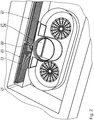
- Fig. 1 and Fig. 2 the two filters 20 are shown in their arrangement on the filter seat 19.
- a first filter 20 is disposed in the filter exchange space 21 between the filter seat 19 and the inflow opening 11.
- a second filter 20 has already been removed from the extractor device 2 and not shown.
- the filter exchange space 21 has a guide device 25 for guided displacement of the two filters 20.
- the guide device 25 is formed by the walls of the filter seat 19. When introducing the filter 20 into the filter seat 19, these are guided between an upper and a lower wall, and by a flow opening 22 having the rear wall of the filter seat 19.
- the filter exchange space 21 comprises a transport channel 26.
- the transport channel 26 extends between the negative pressure channel section 18 and the overpressure channel section 17. Through the transport channel 26 of the respective filter 20 between the filter seat 19 and the inlet opening 11 is displaced.
- the filter exchange space 21 has a closure flap 27.
- the closure flap 27 is designed to close the filter exchange space 21 in a fluid-tight manner against a flow of cooking fumes.
- the closure flap 27 is articulated to the flow channel 12.
- the closure flap 27 is displaceable between a closure position 28, in which the filter exchange space 21 is closed in a fluid-tight manner, and an open position 29, in which the filter exchange space is open for the reversible removal of the two filters 20.
- the closure flap 27 can be opened in the direction of the vacuum channel section 18. Alternatively, the closure flap 27 can also be opened in the direction of the overpressure channel section 17.
- the control unit 9 is designed to operate the hob 3 and the extractor device 2, in particular the two fans 14.
- the extractor device 2 has a sensor device 30.
- the sensor device 30 comprises a filter sensor 31 for detecting the arrangement of the two filters 20 on the filter seat 19.
- the sensor device 30 is in Signal connection with the control unit 9.
- the control unit 9 is designed to interrupt the operation of the fan 14 based on a signal of the sensor device 30.
- the sensor device 30 is embodied such that a signal for interrupting the operation of the fan 14 is provided, provided that the filter sensor 31 detects a missing and / or incorrect arrangement of the two filters 20 on the filter seat 19.
- the sensor device 30 has a closure flap sensor 32 for detecting an arrangement of the closure flap 27.
- the sensor device 30 is designed to provide a signal for interrupting the operation of the fan 14, provided that the shutter sensor 32 detects an arrangement of the shutter 27 outside the closed position 28.
- the flow opening 22 has a major dimension s F, the major dimension F s is greater than a major dimension E s of the inflow port 11.
- An opening area A F of the flow opening 22 is greater than an inflow area A E of the inflow opening. 11
- the two filters 20 are formed deformable.
- the two filters 20 each have a main extension 33.
- the two filters 20 are integrally formed and stretch-resistant in the direction of the main extension 33.
- To a perpendicular to the main extension 33 oriented axis, the two filters 20 are formed pliable.
- For reversible removal of the respective filter 20 is formed bendable about a vertical axis.
- the extractor device 2 has a drive device 34 for the automated displacement of the two filters 20 in the filter exchange space 21.
- the drive means 34 is adapted to the respective filter 20 along the guide means 25 to the filter seat 19 and to move from the filter seat 19 in the direction of the inflow opening 11.
- the drive device 34 is in correct communication with the filter sensor 31 for positioning the respective filter 20.
- the operation of the hob system 1 is as follows: The hob system 1 is controllable via the control unit 9. User inputs are passed from the user interface 10 to the control unit 9.
- the control unit 9 is in signal communication with the cooking zones 7 and the fan motors 16. The control unit 9 allows the adjustment of the cooking points 7 and the fan motors 16 supplied power.
- the fan motors 16 When the fan motors 16 are supplied with electrical power, a torque is transmitted to the fan wheels 15.
- the rotating fan wheels 15 produce a lower negative pressure in the negative pressure channel section 18 than an ambient pressure and a higher overpressure in the overpressure channel section 17 than the ambient pressure.
- Fig. 1 and Fig. 2 the filters 20 are shown arranged on the filter seat 19.
- the filter sensors 31 detect the arrangement of the filters 20 on the filter seat 19.
- the shutter 27 is in the closed position 28.
- the shutter sensor 32 detects the arrangement of the shutter 27 in the closed position 28. The operation of the two fans 14 and their Supply of electrical power are released.
- the closure flap 27 is arranged in the open position 29.
- the first filter 20 is displaced along the filter exchange space 21 in the direction of the inflow opening 11 and the second filter 20 is already removed from the extractor device 2.
- the filter sensor 31 detects the displacement of the respective filter 20 from the filter seat 19.
- the closure flap sensor 32 detects the arrangement of the closure flap 27 in the open position 29.
- the control unit 9 detects a signal from the sensor device 32 to interrupt the operation of the two fans 14 The operation of the two fan motors 16 is interrupted.
- the removal of the two filters 20 from the filter seat 19 and the insertion into the filter seat 19 is partially automated.
- the drive device 24 is in engagement with the respective filter 20.
- the respective filter 20 is displaced along the guide device 25.
- the filter For removal of the respective filter 20 through the filter exchange space 21 and the inflow opening 11 this is curved about a vertical axis, in particular rolled. In the curved shape, the filter is 20 through the inlet opening 11 from the extractor device removed.
- the respective filter 20 is first deformed, in particular curved about the vertical axis, then introduced through the inflow opening 11 in the negative pressure channel section 18 and along the filter exchange space 21 through the transport channel 26 and from the Guiding device 25 guided displaced to the filter seat 19.
- the displacement of the respective filter 20 is partially automated by actuation of the drive means 34.
- the filter sensors 31 detect the arrangement of the respective filter 20 on the filter seat 19.
- the closure flap 27 is displaced into the closure position 28 and the closure flap sensor 32 detects the arrangement the shutter 27 in the closed position 28. The signal for interrupting the operation of the two fans 14 is canceled and the operation of the two fans 14 can be resumed.
- the extractor device 2 only a fan 14.
- a single filter 20 can be arranged.
- the displacement of the filter 20 within the filter exchange space 21 is completely manual, especially by hand.
- the filter exchange space 21 has a transport channel 26.
- the wall of the transport channel 26 is designed to guide the filter 20 and forms part of the guide device 25.
- the transport channel 26 extends between the vacuum channel section 18 and the overpressure channel section 17.
- the filter exchange space 21 by means of the flap 27 is reversibly closed.
- the extractor device 2 has a fan 14 and a filter 20 which can be arranged on the filter seat 19, wherein the transport channel 26 is designed to be simply curved.
- the closure flap 27 is arranged on the part of the overpressure channel section 17 of the transport channel 26.
- the closure flap 27 can be actuated by the drive device 34.
- the drive device 34 is designed to displace the filter 20 along the filter exchange space 21.
- the flow opening 22 is flat.
- a program for removing the filter 20 in the control unit 9 is activated via the user interface 10.
- the closure flap 27 is displaced from the closed position 28 into the open position 29 by means of the drive device 34.
- the filter 20 is then displaced along the transport channel 26 through the filter exchange space 21 into the negative pressure channel section 18. The filter 20 can then be removed by hand from the inflow opening 11.
- Fig. 9 another embodiment of the invention is described.
- the fan 15 of the fan 14 is arranged centrally below the inlet opening 11.
- the fan 15 is dimensioned such that it can be removed from the inflow opening 11.
- the filter exchange space 21 is formed by the flow channel 12.
- the fan 15 is first removed from the flow channel 12 through the inlet opening 11.
- the filter replacement space 21 formed by the flow channel 12 is released to such an extent that the filter 20 can be removed from the filter seat 19 through the inflow opening 11.
- the extractor device 2 according to this embodiment has no transport channel 26 and a closure flap 27 is not necessary.
- the embodiment according to Fig. 9 underlying features are arbitrarily combined with those of the previous embodiments.
- the flow opening 22 is formed curved.
- the filter 20 is disposed on the filter seat 19 in a curved shape.
- the filter exchange space 21 comprises the transport channel 26 and can be closed by means of the closure flap 27 against flowing through cooking fumes.
- a guide means 25 is arranged in the form of a slide guide in the filter change space 21.
- the filter exchange space 21 has a groove in which a frame of the filter 20 is at least partially linearly displaceably mounted.
- the filter seat is flat.
- the filter 20 is displaced along the slotted guide, wherein first an end of the filter 20 facing the inflow opening 11 is curved.
- the filter 20 is hereafter in the in Fig. 10 position shown.
- the filter 20 is displaced further along the slotted guide in the direction of the inflow opening 11.
Landscapes
- Engineering & Computer Science (AREA)
- Chemical & Material Sciences (AREA)
- Combustion & Propulsion (AREA)
- Mechanical Engineering (AREA)
- General Engineering & Computer Science (AREA)
- Chemical Kinetics & Catalysis (AREA)
- Filtering Of Dispersed Particles In Gases (AREA)
- Ventilation (AREA)
- Air Conditioning Control Device (AREA)
- Disinfection, Sterilisation Or Deodorisation Of Air (AREA)
- Processing Of Solid Wastes (AREA)
- General Preparation And Processing Of Foods (AREA)
- Cookers (AREA)
- Seasonings (AREA)
Priority Applications (2)
| Application Number | Priority Date | Filing Date | Title |
|---|---|---|---|
| EP20217002.3A EP3832213B1 (fr) | 2017-12-27 | 2018-12-18 | Hotte aspirante destinée à l'aspiration des vapeurs de cuisson vers le bas |
| EP22178847.4A EP4080123A1 (fr) | 2017-12-27 | 2018-12-18 | Hotte aspirante destinée à l'aspiration des vapeurs de cuisson vers le bas |
Applications Claiming Priority (1)
| Application Number | Priority Date | Filing Date | Title |
|---|---|---|---|
| DE102017223828.3A DE102017223828A1 (de) | 2017-12-27 | 2017-12-27 | Dunstabzugsvorrichtung zum Abzug von Kochdünsten nach unten |
Related Child Applications (3)
| Application Number | Title | Priority Date | Filing Date |
|---|---|---|---|
| EP20217002.3A Division-Into EP3832213B1 (fr) | 2017-12-27 | 2018-12-18 | Hotte aspirante destinée à l'aspiration des vapeurs de cuisson vers le bas |
| EP20217002.3A Division EP3832213B1 (fr) | 2017-12-27 | 2018-12-18 | Hotte aspirante destinée à l'aspiration des vapeurs de cuisson vers le bas |
| EP22178847.4A Division EP4080123A1 (fr) | 2017-12-27 | 2018-12-18 | Hotte aspirante destinée à l'aspiration des vapeurs de cuisson vers le bas |
Publications (2)
| Publication Number | Publication Date |
|---|---|
| EP3505830A1 true EP3505830A1 (fr) | 2019-07-03 |
| EP3505830B1 EP3505830B1 (fr) | 2021-03-24 |
Family
ID=64744538
Family Applications (3)
| Application Number | Title | Priority Date | Filing Date |
|---|---|---|---|
| EP18213259.7A Active EP3505830B1 (fr) | 2017-12-27 | 2018-12-18 | Dispositif formant hotte aspirante permettant d'aspirer les vapeurs de cuisson vers le bas |
| EP20217002.3A Active EP3832213B1 (fr) | 2017-12-27 | 2018-12-18 | Hotte aspirante destinée à l'aspiration des vapeurs de cuisson vers le bas |
| EP22178847.4A Pending EP4080123A1 (fr) | 2017-12-27 | 2018-12-18 | Hotte aspirante destinée à l'aspiration des vapeurs de cuisson vers le bas |
Family Applications After (2)
| Application Number | Title | Priority Date | Filing Date |
|---|---|---|---|
| EP20217002.3A Active EP3832213B1 (fr) | 2017-12-27 | 2018-12-18 | Hotte aspirante destinée à l'aspiration des vapeurs de cuisson vers le bas |
| EP22178847.4A Pending EP4080123A1 (fr) | 2017-12-27 | 2018-12-18 | Hotte aspirante destinée à l'aspiration des vapeurs de cuisson vers le bas |
Country Status (10)
| Country | Link |
|---|---|
| US (1) | US11193675B2 (fr) |
| EP (3) | EP3505830B1 (fr) |
| JP (1) | JP7441604B2 (fr) |
| KR (1) | KR102559217B1 (fr) |
| CN (1) | CN110017518B (fr) |
| AU (2) | AU2018278944B2 (fr) |
| CA (1) | CA3028316A1 (fr) |
| DE (2) | DE102017223828A1 (fr) |
| ES (2) | ES2875370T3 (fr) |
| TW (1) | TWI801478B (fr) |
Cited By (3)
| Publication number | Priority date | Publication date | Assignee | Title |
|---|---|---|---|---|
| EP3978811A1 (fr) * | 2020-10-02 | 2022-04-06 | Miele & Cie. KG | Unité de hotte aspirante à monter en dessous d'une plaque de cuisson, unité de filtre anti-odeurs, système de hotte aspirante et procédé de fonctionnement d'un système de hotte aspirante |
| EP4043797A1 (fr) * | 2021-02-10 | 2022-08-17 | V-Zug AG | Hotte aspirante dans plaque de cuisson |
| WO2024046675A1 (fr) * | 2022-08-30 | 2024-03-07 | Electrolux Appliances Aktiebolag | Élément ou ensemble de filtre, unité d'extraction de fumée et appareil de combinaison |
Families Citing this family (19)
| Publication number | Priority date | Publication date | Assignee | Title |
|---|---|---|---|---|
| IT201700095549A1 (it) * | 2017-08-23 | 2019-02-23 | Elica Spa | Piano cottura |
| DE102017217853B4 (de) * | 2017-10-06 | 2022-07-07 | Wilhelm Bruckbauer | Kochfeldsystem mit Dunstabzugsvorrichtung |
| DE102017223828A1 (de) | 2017-12-27 | 2019-06-27 | Wilhelm Bruckbauer | Dunstabzugsvorrichtung zum Abzug von Kochdünsten nach unten |
| DE102019210395A1 (de) * | 2019-07-15 | 2021-01-21 | BSH Hausgeräte GmbH | Gargerätevorrichtung |
| IT202000016360A1 (it) * | 2020-07-07 | 2022-01-07 | Elica Spa | Piano cottura con cappa aspirante |
| EP3951270A1 (fr) * | 2020-08-05 | 2022-02-09 | Electrolux Appliances Aktiebolag | Appareil combiné |
| DE102020215267A1 (de) * | 2020-12-03 | 2022-06-09 | Vorwerk & Co. Interholding Gesellschaft mit beschränkter Haftung | Filtervorrichtung für eine Küchenmaschine und Küchenmaschine |
| EP4030104A1 (fr) * | 2021-01-14 | 2022-07-20 | Electrolux Appliances Aktiebolag | Dispositif d'extraction |
| DE102021206930B4 (de) | 2021-07-01 | 2024-11-07 | BORA - Vertriebs GmbH & Co KG | Filter-Einrichtung |
| DE202021105496U1 (de) | 2021-09-17 | 2021-12-07 | Silverline Endüstri ve Ticaret A.S. | Kochfeldmodul |
| DK4151909T3 (da) | 2021-09-17 | 2025-05-19 | Silverline Enduestri Ve Ticaret A S | Kogeplademodul |
| EP4246046A1 (fr) * | 2022-03-15 | 2023-09-20 | Electrolux Appliances Aktiebolag | Appareil de combinaison et procédé d'assemblage d'un appareil de combinaison |
| CN117091179A (zh) * | 2022-05-13 | 2023-11-21 | 佛山市顺德区美的电热电器制造有限公司 | 集成灶 |
| DE102022123338A1 (de) * | 2022-09-13 | 2024-03-14 | Berbel Ablufttechnik Gmbh | Dunstabzug und Kombinationsgerät |
| WO2024263029A1 (fr) * | 2023-06-20 | 2024-12-26 | Plasmamade B.V. | Dispositif extracteur à intégration inférieure, placard de cuisine doté d'un tel dispositif et procédé d'extraction de vapeurs de cuisson |
| NL2035129B1 (nl) * | 2023-06-20 | 2025-01-06 | Plasmamade B V | Onderbouw-afzuiginrichting, kookplaat en werkwijze |
| DE102023125203A1 (de) * | 2023-09-18 | 2025-03-20 | Berbel Ablufttechnik Gmbh | Dunstabzug und Kombinationsgerät |
| TWI895852B (zh) * | 2023-11-10 | 2025-09-01 | 研能科技股份有限公司 | 室內場域之廚房單元空污防治系統 |
| DE102024206186A1 (de) | 2024-07-02 | 2026-01-08 | BSH Hausgeräte GmbH | Geruchsfiltereinheit für Dunstabzugsvorrichtung |
Citations (6)
| Publication number | Priority date | Publication date | Assignee | Title |
|---|---|---|---|---|
| US4846146A (en) * | 1988-01-15 | 1989-07-11 | Tucker James L | Cooking apparatus ventilation system with recycling air flow |
| US4962694A (en) * | 1988-04-15 | 1990-10-16 | Graver James H | Grill exhaust system |
| DE102011082924A1 (de) * | 2011-09-19 | 2013-03-21 | BSH Bosch und Siemens Hausgeräte GmbH | Dunstabzugsvorrichtung und Verfahren zum Betreiben einer Dunstabzugsvorrichtung |
| WO2017089925A1 (fr) * | 2015-11-27 | 2017-06-01 | Elica S.P.A | Hotte à usage domestique |
| DE102016109136A1 (de) * | 2016-05-18 | 2017-11-23 | Eisfink Max Maier Gmbh & Co. Kg | Front-Cooking-Station |
| WO2019038632A1 (fr) * | 2017-08-23 | 2019-02-28 | Elica S.P.A. | Table de cuisson |
Family Cites Families (77)
| Publication number | Priority date | Publication date | Assignee | Title |
|---|---|---|---|---|
| US1521577A (en) * | 1921-01-05 | 1924-12-30 | Wittemeier Hans | Filter for purifying the air |
| US3719137A (en) | 1971-12-01 | 1973-03-06 | Gen Motors Corp | Range ventilating system |
| FR2274332A1 (fr) | 1974-06-17 | 1976-01-09 | Sermet Pierre | Dispositif de filtration par ventilation, notamment pour appareils electro-menagers |
| US4562827A (en) | 1984-11-21 | 1986-01-07 | Roper Corporation | Downdraft countertop cooking range |
| JPH01137137A (ja) * | 1987-11-24 | 1989-05-30 | Matsushita Seiko Co Ltd | レンジフード |
| US5211159A (en) | 1988-12-02 | 1993-05-18 | Standex International Corporation | Exhaust hood with disposable filter assembly and filter-condition sensor |
| US5268012A (en) * | 1993-01-29 | 1993-12-07 | Jang Sun Sing | Fume extractor |
| US5679122A (en) | 1993-08-14 | 1997-10-21 | Minnesota Mining & Manufacturing Company | Filter for the filtration of a fluid flow |
| US5482622A (en) * | 1994-04-18 | 1996-01-09 | General Motors Corporation | Filter for installation in an annular groove |
| US5738083A (en) * | 1995-01-12 | 1998-04-14 | Turboaire S.P.A. | Flow deflector for filtration hood |
| JPH08103615A (ja) * | 1995-10-09 | 1996-04-23 | Hitachi Ltd | 脱臭機能付エアクリーナ |
| JPH10165242A (ja) * | 1996-12-10 | 1998-06-23 | Toshiba Corp | 組み込み式加熱調理器 |
| JPH10176855A (ja) * | 1996-12-16 | 1998-06-30 | Fuji Kogyo Corp | レンジフード |
| AUPO532397A0 (en) * | 1997-02-26 | 1997-03-20 | I.D.E.A. (Industrial Design And Engineering Associates) Pty Ltd | Combined light source/air purifier |
| JPH11108408A (ja) | 1997-09-30 | 1999-04-23 | Yamatoyo Sangyo Kk | レンジフード用フィルタ装置 |
| US6050774A (en) * | 1997-10-14 | 2000-04-18 | Huntair Inc. | Modular filter fan unit |
| JP3982919B2 (ja) * | 1998-08-24 | 2007-09-26 | 三洋電機株式会社 | 有機物処理装置 |
| JP3466982B2 (ja) | 2000-03-06 | 2003-11-17 | 株式会社ノリタケカンパニーリミテド | 無煙調理器 |
| US6471738B1 (en) * | 2000-03-22 | 2002-10-29 | Health & Home Technologies | Ceiling-mounted air filtration device |
| EP1275428B1 (fr) | 2001-07-13 | 2005-03-23 | helsa-automotive GmbH & Co. KG | Filtre flexible |
| US6455818B1 (en) * | 2001-08-23 | 2002-09-24 | Maytag Corporation | Downdraft filter assembly for a cooking appliance |
| DE10146153A1 (de) | 2001-09-19 | 2003-04-10 | Bsh Bosch Siemens Hausgeraete | Mobile Dunstabzugsvorrichtung |
| KR100432693B1 (ko) * | 2001-12-24 | 2004-05-22 | 위니아만도 주식회사 | 에어컨 실내기의 프레임필터 승강장치 |
| DE10216012A1 (de) * | 2002-04-11 | 2003-10-30 | Max Maier | Dunstabsaugvorrichtung für ein Kochfeld od. dgl. und insbesondere dafür geeigneter Fettfilter |
| JP2004160409A (ja) * | 2002-11-15 | 2004-06-10 | Hitachi Ltd | 空気清浄機 |
| KR100848161B1 (ko) * | 2002-11-29 | 2008-07-23 | 삼성전자주식회사 | 공기정화장치를 구비한 조리기 |
| CN100343585C (zh) * | 2003-04-25 | 2007-10-17 | 乐金电子(天津)电器有限公司 | 微波炉的排气结构 |
| WO2005017414A1 (fr) | 2003-08-07 | 2005-02-24 | BSH Bosch und Siemens Hausgeräte GmbH | Systeme filtrant |
| US7571721B2 (en) * | 2005-09-14 | 2009-08-11 | Franklin Machines Products | Baffle-type grease filter for kitchen ventilators |
| DE102006039247A1 (de) * | 2006-08-22 | 2008-04-10 | Mann + Hummel Gmbh | Flexibles Filterelement |
| US8851064B2 (en) | 2007-01-10 | 2014-10-07 | Wilhelm Bruckbauer | Device for removing cooking vapors comprising a flat exhaust air duct |
| JP2008221180A (ja) * | 2007-03-15 | 2008-09-25 | Nitta Ind Corp | エアフィルタのシール構造 |
| DE102008033792B4 (de) * | 2008-07-18 | 2021-04-29 | BSH Hausgeräte GmbH | Umluftmodul und Dunstabzugsvorrichtung |
| CN101358747B (zh) * | 2008-09-12 | 2010-11-24 | 宁波方太厨具有限公司 | 一种方便拆洗的油烟过滤装置 |
| DE202008013350U1 (de) * | 2008-10-11 | 2009-01-08 | Bruckbauer, Wilhelm | Vorrichtung zum Kochen mit Spül-Luftzuführung und Spül-Luftabsaugung |
| DE102008054775A1 (de) * | 2008-12-16 | 2010-06-17 | BSH Bosch und Siemens Hausgeräte GmbH | Luftaufbereitungsvorrichtung und Verfahren zum Detektieren eines Filterelementes in einer Luftaufbereitungsvorrichtung |
| WO2011028729A1 (fr) | 2009-09-01 | 2011-03-10 | Manitowoc Foodservice Companies, Llc | Procédé et appareil pour une entrée d'air dans un dispositif de cuisson |
| DE202009017271U1 (de) | 2009-12-19 | 2010-03-25 | Mahle International Gmbh | Dunstabzugshaube |
| US20110146657A1 (en) * | 2009-12-21 | 2011-06-23 | Whirlpool Corporation | Duct free re-circulating downdraft exhaust accessory |
| DE102010005113A1 (de) * | 2010-01-19 | 2011-07-21 | Mann + Hummel GmbH, 71638 | Filteranordnung |
| JP5440233B2 (ja) * | 2010-02-12 | 2014-03-12 | 株式会社リコー | 画像形成装置 |
| US20120111197A1 (en) | 2010-11-10 | 2012-05-10 | Energy Management Products, Llc | Filter rack, filter assembly, and method of filtering air |
| US20120204855A1 (en) * | 2011-02-04 | 2012-08-16 | Huber John J | Cooking Device with Ventilation and Filtration System |
| JP5255664B2 (ja) * | 2011-02-18 | 2013-08-07 | シャープ株式会社 | フィルター及びそれを用いた空気調節装置 |
| DE202011005698U1 (de) | 2011-04-28 | 2011-09-26 | Wilhelm Bruckbauer | Kochfeld mit zentraler Absaugung von Kochdünsten nach unten |
| DE102011018962C5 (de) * | 2011-04-28 | 2025-11-20 | Werkhaus GmbH & Co. KG | Kochfeld mit zentraler Absaugung von Kochdünsten nach unten |
| DE102011079793A1 (de) * | 2011-07-26 | 2013-01-31 | BSH Bosch und Siemens Hausgeräte GmbH | Dunstabzugshaube |
| US20130199142A1 (en) | 2011-11-17 | 2013-08-08 | Jack R. Kerr, Jr. | System and Method For Replacing a Return Air Filter |
| CN102654300B (zh) * | 2012-04-26 | 2014-06-11 | 中国建筑西北设计研究院有限公司 | 一种具有照明能力的室外进风系统 |
| DE102012207850B4 (de) * | 2012-05-11 | 2022-03-10 | BSH Hausgeräte GmbH | Absaugvorrichtung zum Absaugen von Luft von einem Herd |
| US20140079595A1 (en) * | 2012-09-14 | 2014-03-20 | Kompass Technology Co., Ltd. | Embedded multifunctional air purifier used in kitchen |
| JP2014083484A (ja) * | 2012-10-22 | 2014-05-12 | Kankyo Co Ltd | 空気清浄機及び加湿器 |
| DE102012022571A1 (de) * | 2012-11-20 | 2014-05-22 | minEnergy GmbH | Dunstabzugshaube |
| JP5522306B1 (ja) * | 2012-12-21 | 2014-06-18 | ダイキン工業株式会社 | 遠心ファン |
| US9746188B2 (en) | 2013-03-27 | 2017-08-29 | Electrolux Home Products, Inc. | Recirculating downdraft system for a cooking appliance |
| DE102013007722B4 (de) | 2013-05-07 | 2021-03-04 | BORA - Vertriebs GmbH & Co KG | Muldenlüftung zum Abzug von Kochdampf an einem Kochfeld |
| DE202013005303U1 (de) | 2013-06-12 | 2013-06-24 | Wilhelm Bruckbauer | Kochfeld |
| US20160296870A1 (en) | 2015-04-13 | 2016-10-13 | Electrolux Home Products, Inc. | Vent filter and appliance utilizing such a filter |
| DE202016104283U1 (de) | 2015-08-07 | 2016-08-09 | Airforce S.P.A. | Vorrichtung zum Filtern von Dünsten und Dämpfen vom Kochen |
| EP3338030B1 (fr) * | 2015-08-19 | 2019-12-18 | BSH Hausgeräte GmbH | Appareil combiné avec plaque de cuisson et dispositif d'evacuation des fumées avec unité de filtration |
| CN107923631B (zh) | 2015-08-19 | 2020-09-18 | Bsh家用电器有限公司 | 具有烹调区域和排烟设备的组合式装置 |
| EP3338028B1 (fr) | 2015-08-19 | 2020-04-29 | BSH Hausgeräte GmbH | Appareil combiné avec plaque de cuisson et dispositif d'evacuation des fumées |
| EP3338029B1 (fr) * | 2015-08-19 | 2022-03-09 | BSH Hausgeräte GmbH | Appareil combiné avec plaque de cuisson et dispositif d'evacuation des fumées |
| GB2533466A (en) * | 2015-10-22 | 2016-06-22 | Darwin Tech Int Ltd | Air cleaning device |
| CN108348831B (zh) * | 2015-11-10 | 2021-04-13 | Bsh家用电器有限公司 | 用于蒸汽排除装置的过滤装置和蒸汽排除装置 |
| US10837659B2 (en) * | 2015-12-02 | 2020-11-17 | Coway Co., Ltd. | Air purifier |
| ITUB20159323A1 (it) | 2015-12-18 | 2017-06-18 | Elica Spa | Cappa di aspirazione per ambienti domestici. |
| ITUA20162311A1 (it) | 2016-04-05 | 2017-10-05 | Elica Spa | Piano cottura con cappa integrata. |
| DE102016211207B4 (de) | 2016-06-22 | 2025-03-13 | Werkhaus GmbH & Co. KG | Vorrichtung zum Abzug von Kochdünsten |
| DE102016211206A1 (de) | 2016-06-22 | 2017-12-28 | Wilhelm Bruckbauer | Einsatz für einen Muldenlüfter |
| IT201600078092A1 (it) * | 2016-07-26 | 2018-01-26 | Elica Spa | Piano cottura. |
| US10863648B2 (en) * | 2016-09-07 | 2020-12-08 | Dell Products L.P. | Modular fan chassis air filtering system |
| DE102016117537A1 (de) * | 2016-09-16 | 2018-04-12 | Berling Aero IP UG (haftungsbeschränkt) | Dunstabzugsvorrichtung mit Ansaugstutzen |
| CN108253481A (zh) | 2016-12-29 | 2018-07-06 | 宁波方太厨具有限公司 | 一种吸油烟机 |
| EP3701192B1 (fr) | 2017-10-26 | 2024-12-11 | BSH Hausgeräte GmbH | Appareil combiné comprenant un dispositif d'aspiration de fumées et une plaque de cuisson |
| DE102017223828A1 (de) | 2017-12-27 | 2019-06-27 | Wilhelm Bruckbauer | Dunstabzugsvorrichtung zum Abzug von Kochdünsten nach unten |
| DE102018206642A1 (de) * | 2018-04-27 | 2019-10-31 | Wilhelm Bruckbauer | Luftleitsystem |
-
2017
- 2017-12-27 DE DE102017223828.3A patent/DE102017223828A1/de not_active Ceased
-
2018
- 2018-12-13 AU AU2018278944A patent/AU2018278944B2/en active Active
- 2018-12-18 EP EP18213259.7A patent/EP3505830B1/fr active Active
- 2018-12-18 DE DE202018006525.0U patent/DE202018006525U1/de active Active
- 2018-12-18 EP EP20217002.3A patent/EP3832213B1/fr active Active
- 2018-12-18 ES ES18213259T patent/ES2875370T3/es active Active
- 2018-12-18 EP EP22178847.4A patent/EP4080123A1/fr active Pending
- 2018-12-18 ES ES20217002T patent/ES2924752T3/es active Active
- 2018-12-20 JP JP2018238138A patent/JP7441604B2/ja active Active
- 2018-12-21 CA CA3028316A patent/CA3028316A1/fr active Pending
- 2018-12-21 US US16/230,166 patent/US11193675B2/en active Active
- 2018-12-26 CN CN201811600432.0A patent/CN110017518B/zh active Active
- 2018-12-26 TW TW107147198A patent/TWI801478B/zh active
- 2018-12-27 KR KR1020180170258A patent/KR102559217B1/ko active Active
-
2021
- 2021-08-06 AU AU2021105061A patent/AU2021105061A4/en active Active
Patent Citations (6)
| Publication number | Priority date | Publication date | Assignee | Title |
|---|---|---|---|---|
| US4846146A (en) * | 1988-01-15 | 1989-07-11 | Tucker James L | Cooking apparatus ventilation system with recycling air flow |
| US4962694A (en) * | 1988-04-15 | 1990-10-16 | Graver James H | Grill exhaust system |
| DE102011082924A1 (de) * | 2011-09-19 | 2013-03-21 | BSH Bosch und Siemens Hausgeräte GmbH | Dunstabzugsvorrichtung und Verfahren zum Betreiben einer Dunstabzugsvorrichtung |
| WO2017089925A1 (fr) * | 2015-11-27 | 2017-06-01 | Elica S.P.A | Hotte à usage domestique |
| DE102016109136A1 (de) * | 2016-05-18 | 2017-11-23 | Eisfink Max Maier Gmbh & Co. Kg | Front-Cooking-Station |
| WO2019038632A1 (fr) * | 2017-08-23 | 2019-02-28 | Elica S.P.A. | Table de cuisson |
Cited By (3)
| Publication number | Priority date | Publication date | Assignee | Title |
|---|---|---|---|---|
| EP3978811A1 (fr) * | 2020-10-02 | 2022-04-06 | Miele & Cie. KG | Unité de hotte aspirante à monter en dessous d'une plaque de cuisson, unité de filtre anti-odeurs, système de hotte aspirante et procédé de fonctionnement d'un système de hotte aspirante |
| EP4043797A1 (fr) * | 2021-02-10 | 2022-08-17 | V-Zug AG | Hotte aspirante dans plaque de cuisson |
| WO2024046675A1 (fr) * | 2022-08-30 | 2024-03-07 | Electrolux Appliances Aktiebolag | Élément ou ensemble de filtre, unité d'extraction de fumée et appareil de combinaison |
Also Published As
| Publication number | Publication date |
|---|---|
| ES2924752T3 (es) | 2022-10-10 |
| KR20190079576A (ko) | 2019-07-05 |
| DE202018006525U1 (de) | 2021-01-13 |
| DE102017223828A1 (de) | 2019-06-27 |
| ES2875370T3 (es) | 2021-11-10 |
| EP3505830B1 (fr) | 2021-03-24 |
| EP4080123A1 (fr) | 2022-10-26 |
| JP2019120486A (ja) | 2019-07-22 |
| EP3832213B1 (fr) | 2022-06-15 |
| TW201930791A (zh) | 2019-08-01 |
| CN110017518B (zh) | 2022-06-17 |
| AU2018278944A1 (en) | 2019-07-11 |
| KR102559217B1 (ko) | 2023-07-24 |
| TWI801478B (zh) | 2023-05-11 |
| JP7441604B2 (ja) | 2024-03-01 |
| US11193675B2 (en) | 2021-12-07 |
| AU2018278944B2 (en) | 2023-04-13 |
| CN110017518A (zh) | 2019-07-16 |
| US20190195511A1 (en) | 2019-06-27 |
| EP3832213A1 (fr) | 2021-06-09 |
| AU2021105061A4 (en) | 2021-09-30 |
| CA3028316A1 (fr) | 2019-06-27 |
Similar Documents
| Publication | Publication Date | Title |
|---|---|---|
| EP3505830B1 (fr) | Dispositif formant hotte aspirante permettant d'aspirer les vapeurs de cuisson vers le bas | |
| EP3475621B1 (fr) | Dispositif pour l'évacuation de vapeurs de cuisson | |
| EP3953645B1 (fr) | Dispositif pour faire chauffer un aliment à cuire | |
| DE102017217853B4 (de) | Kochfeldsystem mit Dunstabzugsvorrichtung | |
| EP3475622B1 (fr) | Système de ventilation à courant descendant avec un insert | |
| DE102009025038A1 (de) | Kochdunst-Eintrittsvorrichtung mit abnehmbarer deckelförmiger Verschließeinrichtung | |
| EP3045824B1 (fr) | Dispositif d'aspiration d'air d'une cuisiniere | |
| DE202009008286U1 (de) | Kochdunst-Eintrittsvorrichtung mit abnehmbarer deckelförmiger Verschließeinrichtung | |
| DE102018215480A1 (de) | Dunstabzugsvorrichtung mit Verschlussklappe | |
| DE102019216343A1 (de) | Gargerät mit spezifischer Zuluftvorrichtung | |
| EP2857758B1 (fr) | Dispositif d'aspiration de vapeur | |
| DE102014108237A1 (de) | Dunstabzugshaube | |
| EP2487424B1 (fr) | Hotte aspirante pour un four, une plaque de cuisson ou analogue | |
| DE102019109401B4 (de) | Lüftereinrichtung zum Ansaugen und Ableiten von Wrasen nach unterhalb eines Kochfeldes und Kochfeld | |
| EP3788264B1 (fr) | Dispositif de purification d'air, en particulier pour vapeurs de cuisine, et utilisation de celui-ci | |
| DE102017012370B4 (de) | Dunstabzugsvorrichtung zum Abzug von Kochdünsten nach unten | |
| EP2944883A1 (fr) | Dispositif de hotte aspirante et procédé | |
| EP3348913B1 (fr) | Hotte aspirante et procédé de fonctionnement | |
| EP3825613B1 (fr) | Hotte aspirante | |
| EP2955450B1 (fr) | Hotte aspirante | |
| DE102007003934A1 (de) | Dunstabzugshaube | |
| DE102016015901B4 (de) | Vorrichtung zum Abzug von Kochdünsten | |
| DE102018110780A1 (de) | Kochstellenanordnung mit Verbindungselement | |
| DE202013105077U1 (de) | Dunstabzugshaube | |
| DE102022115304A1 (de) | Lüfter, Dunstabzug, und Kombinationsgerät |
Legal Events
| Date | Code | Title | Description |
|---|---|---|---|
| REG | Reference to a national code |
Ref country code: DE Ref legal event code: R138 Ref document number: 202018006525 Country of ref document: DE Free format text: GERMAN DOCUMENT NUMBER IS 502018004428 |
|
| PUAI | Public reference made under article 153(3) epc to a published international application that has entered the european phase |
Free format text: ORIGINAL CODE: 0009012 |
|
| STAA | Information on the status of an ep patent application or granted ep patent |
Free format text: STATUS: THE APPLICATION HAS BEEN PUBLISHED |
|
| AK | Designated contracting states |
Kind code of ref document: A1 Designated state(s): AL AT BE BG CH CY CZ DE DK EE ES FI FR GB GR HR HU IE IS IT LI LT LU LV MC MK MT NL NO PL PT RO RS SE SI SK SM TR |
|
| AX | Request for extension of the european patent |
Extension state: BA ME |
|
| STAA | Information on the status of an ep patent application or granted ep patent |
Free format text: STATUS: REQUEST FOR EXAMINATION WAS MADE |
|
| 17P | Request for examination filed |
Effective date: 20191217 |
|
| RBV | Designated contracting states (corrected) |
Designated state(s): AL AT BE BG CH CY CZ DE DK EE ES FI FR GB GR HR HU IE IS IT LI LT LU LV MC MK MT NL NO PL PT RO RS SE SI SK SM TR |
|
| GRAP | Despatch of communication of intention to grant a patent |
Free format text: ORIGINAL CODE: EPIDOSNIGR1 |
|
| STAA | Information on the status of an ep patent application or granted ep patent |
Free format text: STATUS: GRANT OF PATENT IS INTENDED |
|
| INTG | Intention to grant announced |
Effective date: 20201023 |
|
| GRAS | Grant fee paid |
Free format text: ORIGINAL CODE: EPIDOSNIGR3 |
|
| GRAA | (expected) grant |
Free format text: ORIGINAL CODE: 0009210 |
|
| STAA | Information on the status of an ep patent application or granted ep patent |
Free format text: STATUS: THE PATENT HAS BEEN GRANTED |
|
| AK | Designated contracting states |
Kind code of ref document: B1 Designated state(s): AL AT BE BG CH CY CZ DE DK EE ES FI FR GB GR HR HU IE IS IT LI LT LU LV MC MK MT NL NO PL PT RO RS SE SI SK SM TR |
|
| REG | Reference to a national code |
Ref country code: GB Ref legal event code: FG4D Free format text: NOT ENGLISH |
|
| REG | Reference to a national code |
Ref country code: CH Ref legal event code: EP |
|
| REG | Reference to a national code |
Ref country code: IE Ref legal event code: FG4D Free format text: LANGUAGE OF EP DOCUMENT: GERMAN |
|
| REG | Reference to a national code |
Ref country code: DE Ref legal event code: R096 Ref document number: 502018004428 Country of ref document: DE Ref country code: AT Ref legal event code: REF Ref document number: 1374855 Country of ref document: AT Kind code of ref document: T Effective date: 20210415 |
|
| REG | Reference to a national code |
Ref country code: SE Ref legal event code: TRGR |
|
| REG | Reference to a national code |
Ref country code: NL Ref legal event code: FP |
|
| REG | Reference to a national code |
Ref country code: LT Ref legal event code: MG9D |
|
| PG25 | Lapsed in a contracting state [announced via postgrant information from national office to epo] |
Ref country code: BG Free format text: LAPSE BECAUSE OF FAILURE TO SUBMIT A TRANSLATION OF THE DESCRIPTION OR TO PAY THE FEE WITHIN THE PRESCRIBED TIME-LIMIT Effective date: 20210624 Ref country code: GR Free format text: LAPSE BECAUSE OF FAILURE TO SUBMIT A TRANSLATION OF THE DESCRIPTION OR TO PAY THE FEE WITHIN THE PRESCRIBED TIME-LIMIT Effective date: 20210625 Ref country code: HR Free format text: LAPSE BECAUSE OF FAILURE TO SUBMIT A TRANSLATION OF THE DESCRIPTION OR TO PAY THE FEE WITHIN THE PRESCRIBED TIME-LIMIT Effective date: 20210324 Ref country code: FI Free format text: LAPSE BECAUSE OF FAILURE TO SUBMIT A TRANSLATION OF THE DESCRIPTION OR TO PAY THE FEE WITHIN THE PRESCRIBED TIME-LIMIT Effective date: 20210324 |
|
| PG25 | Lapsed in a contracting state [announced via postgrant information from national office to epo] |
Ref country code: LV Free format text: LAPSE BECAUSE OF FAILURE TO SUBMIT A TRANSLATION OF THE DESCRIPTION OR TO PAY THE FEE WITHIN THE PRESCRIBED TIME-LIMIT Effective date: 20210324 Ref country code: RS Free format text: LAPSE BECAUSE OF FAILURE TO SUBMIT A TRANSLATION OF THE DESCRIPTION OR TO PAY THE FEE WITHIN THE PRESCRIBED TIME-LIMIT Effective date: 20210324 |
|
| REG | Reference to a national code |
Ref country code: NO Ref legal event code: T2 Effective date: 20210324 |
|
| PG25 | Lapsed in a contracting state [announced via postgrant information from national office to epo] |
Ref country code: CZ Free format text: LAPSE BECAUSE OF FAILURE TO SUBMIT A TRANSLATION OF THE DESCRIPTION OR TO PAY THE FEE WITHIN THE PRESCRIBED TIME-LIMIT Effective date: 20210324 Ref country code: EE Free format text: LAPSE BECAUSE OF FAILURE TO SUBMIT A TRANSLATION OF THE DESCRIPTION OR TO PAY THE FEE WITHIN THE PRESCRIBED TIME-LIMIT Effective date: 20210324 Ref country code: LT Free format text: LAPSE BECAUSE OF FAILURE TO SUBMIT A TRANSLATION OF THE DESCRIPTION OR TO PAY THE FEE WITHIN THE PRESCRIBED TIME-LIMIT Effective date: 20210324 Ref country code: SM Free format text: LAPSE BECAUSE OF FAILURE TO SUBMIT A TRANSLATION OF THE DESCRIPTION OR TO PAY THE FEE WITHIN THE PRESCRIBED TIME-LIMIT Effective date: 20210324 |
|
| REG | Reference to a national code |
Ref country code: ES Ref legal event code: FG2A Ref document number: 2875370 Country of ref document: ES Kind code of ref document: T3 Effective date: 20211110 |
|
| PG25 | Lapsed in a contracting state [announced via postgrant information from national office to epo] |
Ref country code: IS Free format text: LAPSE BECAUSE OF FAILURE TO SUBMIT A TRANSLATION OF THE DESCRIPTION OR TO PAY THE FEE WITHIN THE PRESCRIBED TIME-LIMIT Effective date: 20210724 Ref country code: PT Free format text: LAPSE BECAUSE OF FAILURE TO SUBMIT A TRANSLATION OF THE DESCRIPTION OR TO PAY THE FEE WITHIN THE PRESCRIBED TIME-LIMIT Effective date: 20210726 Ref country code: PL Free format text: LAPSE BECAUSE OF FAILURE TO SUBMIT A TRANSLATION OF THE DESCRIPTION OR TO PAY THE FEE WITHIN THE PRESCRIBED TIME-LIMIT Effective date: 20210324 Ref country code: RO Free format text: LAPSE BECAUSE OF FAILURE TO SUBMIT A TRANSLATION OF THE DESCRIPTION OR TO PAY THE FEE WITHIN THE PRESCRIBED TIME-LIMIT Effective date: 20210324 Ref country code: SK Free format text: LAPSE BECAUSE OF FAILURE TO SUBMIT A TRANSLATION OF THE DESCRIPTION OR TO PAY THE FEE WITHIN THE PRESCRIBED TIME-LIMIT Effective date: 20210324 |
|
| REG | Reference to a national code |
Ref country code: DE Ref legal event code: R026 Ref document number: 502018004428 Country of ref document: DE |
|
| PLBI | Opposition filed |
Free format text: ORIGINAL CODE: 0009260 |
|
| PLAX | Notice of opposition and request to file observation + time limit sent |
Free format text: ORIGINAL CODE: EPIDOSNOBS2 |
|
| 26 | Opposition filed |
Opponent name: BERBEL ABLUFTTECHNIK GMBH Effective date: 20211222 |
|
| PG25 | Lapsed in a contracting state [announced via postgrant information from national office to epo] |
Ref country code: AL Free format text: LAPSE BECAUSE OF FAILURE TO SUBMIT A TRANSLATION OF THE DESCRIPTION OR TO PAY THE FEE WITHIN THE PRESCRIBED TIME-LIMIT Effective date: 20210324 Ref country code: DK Free format text: LAPSE BECAUSE OF FAILURE TO SUBMIT A TRANSLATION OF THE DESCRIPTION OR TO PAY THE FEE WITHIN THE PRESCRIBED TIME-LIMIT Effective date: 20210324 |
|
| PG25 | Lapsed in a contracting state [announced via postgrant information from national office to epo] |
Ref country code: SI Free format text: LAPSE BECAUSE OF FAILURE TO SUBMIT A TRANSLATION OF THE DESCRIPTION OR TO PAY THE FEE WITHIN THE PRESCRIBED TIME-LIMIT Effective date: 20210324 |
|
| PLBB | Reply of patent proprietor to notice(s) of opposition received |
Free format text: ORIGINAL CODE: EPIDOSNOBS3 |
|
| PG25 | Lapsed in a contracting state [announced via postgrant information from national office to epo] |
Ref country code: IS Free format text: LAPSE BECAUSE OF FAILURE TO SUBMIT A TRANSLATION OF THE DESCRIPTION OR TO PAY THE FEE WITHIN THE PRESCRIBED TIME-LIMIT Effective date: 20210724 |
|
| PG25 | Lapsed in a contracting state [announced via postgrant information from national office to epo] |
Ref country code: MC Free format text: LAPSE BECAUSE OF FAILURE TO SUBMIT A TRANSLATION OF THE DESCRIPTION OR TO PAY THE FEE WITHIN THE PRESCRIBED TIME-LIMIT Effective date: 20210324 |
|
| PG25 | Lapsed in a contracting state [announced via postgrant information from national office to epo] |
Ref country code: LU Free format text: LAPSE BECAUSE OF NON-PAYMENT OF DUE FEES Effective date: 20211218 Ref country code: IE Free format text: LAPSE BECAUSE OF NON-PAYMENT OF DUE FEES Effective date: 20211218 |
|
| PG25 | Lapsed in a contracting state [announced via postgrant information from national office to epo] |
Ref country code: CY Free format text: LAPSE BECAUSE OF FAILURE TO SUBMIT A TRANSLATION OF THE DESCRIPTION OR TO PAY THE FEE WITHIN THE PRESCRIBED TIME-LIMIT Effective date: 20210324 |
|
| PG25 | Lapsed in a contracting state [announced via postgrant information from national office to epo] |
Ref country code: HU Free format text: LAPSE BECAUSE OF FAILURE TO SUBMIT A TRANSLATION OF THE DESCRIPTION OR TO PAY THE FEE WITHIN THE PRESCRIBED TIME-LIMIT; INVALID AB INITIO Effective date: 20181218 |
|
| REG | Reference to a national code |
Ref country code: DE Ref legal event code: R100 Ref document number: 502018004428 Country of ref document: DE |
|
| PLCK | Communication despatched that opposition was rejected |
Free format text: ORIGINAL CODE: EPIDOSNREJ1 |
|
| PLBN | Opposition rejected |
Free format text: ORIGINAL CODE: 0009273 |
|
| STAA | Information on the status of an ep patent application or granted ep patent |
Free format text: STATUS: OPPOSITION REJECTED |
|
| 27O | Opposition rejected |
Effective date: 20231114 |
|
| PG25 | Lapsed in a contracting state [announced via postgrant information from national office to epo] |
Ref country code: MK Free format text: LAPSE BECAUSE OF FAILURE TO SUBMIT A TRANSLATION OF THE DESCRIPTION OR TO PAY THE FEE WITHIN THE PRESCRIBED TIME-LIMIT Effective date: 20210324 |
|
| REG | Reference to a national code |
Ref country code: CH Ref legal event code: PK Free format text: DIE PUBLIKATION VOM 27.03.2024 WURDE AM 24.04.2024 IRRTUEMLICHERWEISE ERNEUT PUBLIZIERT. LA PUBLICATION DU 27.03.2024 A ETE REPUBLIEE PAR ERREUR LE 24.04.2024. LA PUBBLICAZIONE DEL 27.03.2024 E STATA ERRONEAMENTE RIPUBBLICATA IL 24.04.2024. |
|
| PG25 | Lapsed in a contracting state [announced via postgrant information from national office to epo] |
Ref country code: MT Free format text: LAPSE BECAUSE OF FAILURE TO SUBMIT A TRANSLATION OF THE DESCRIPTION OR TO PAY THE FEE WITHIN THE PRESCRIBED TIME-LIMIT Effective date: 20210324 |
|
| REG | Reference to a national code |
Ref country code: NL Ref legal event code: PD Owner name: WERKHAUS GMBH & CO. KG; DE Free format text: DETAILS ASSIGNMENT: CHANGE OF OWNER(S), ASSIGNMENT; FORMER OWNER NAME: BRUCKBAUER, WILHELM Effective date: 20241016 |
|
| REG | Reference to a national code |
Ref country code: DE Ref legal event code: R081 Ref document number: 502018004428 Country of ref document: DE Owner name: WERKHAUS GMBH & CO. KG, DE Free format text: FORMER OWNER: BRUCKBAUER, WILHELM, 83115 NEUBEUERN, DE |
|
| REG | Reference to a national code |
Ref country code: GB Ref legal event code: 732E Free format text: REGISTERED BETWEEN 20241017 AND 20241023 |
|
| REG | Reference to a national code |
Ref country code: BE Ref legal event code: PD Owner name: WERKHAUS GMBH & CO. KG; DE Free format text: DETAILS ASSIGNMENT: CHANGE OF OWNER(S), ASSIGNMENT; FORMER OWNER NAME: GANTER PAUL Effective date: 20241017 |
|
| REG | Reference to a national code |
Ref country code: AT Ref legal event code: PC Ref document number: 1374855 Country of ref document: AT Kind code of ref document: T Owner name: WERKHAUS GMBH & CO. KG, DE Effective date: 20241127 |
|
| PGFP | Annual fee paid to national office [announced via postgrant information from national office to epo] |
Ref country code: BE Payment date: 20241216 Year of fee payment: 7 |
|
| REG | Reference to a national code |
Ref country code: ES Ref legal event code: GD2A Effective date: 20250313 |
|
| REG | Reference to a national code |
Ref country code: ES Ref legal event code: PC2A Owner name: WERKHAUS GMBH & CO. KG Effective date: 20250627 |
|
| REG | Reference to a national code |
Ref country code: CH Ref legal event code: U11 Free format text: ST27 STATUS EVENT CODE: U-0-0-U10-U11 (AS PROVIDED BY THE NATIONAL OFFICE) Effective date: 20260101 |
|
| PGFP | Annual fee paid to national office [announced via postgrant information from national office to epo] |
Ref country code: GB Payment date: 20251218 Year of fee payment: 8 |
|
| PGFP | Annual fee paid to national office [announced via postgrant information from national office to epo] |
Ref country code: NO Payment date: 20251216 Year of fee payment: 8 |
|
| PGFP | Annual fee paid to national office [announced via postgrant information from national office to epo] |
Ref country code: AT Payment date: 20251118 Year of fee payment: 8 |
|
| PGFP | Annual fee paid to national office [announced via postgrant information from national office to epo] |
Ref country code: FR Payment date: 20251218 Year of fee payment: 8 Ref country code: NL Payment date: 20251217 Year of fee payment: 8 |
|
| PGFP | Annual fee paid to national office [announced via postgrant information from national office to epo] |
Ref country code: TR Payment date: 20251212 Year of fee payment: 8 |
|
| PGFP | Annual fee paid to national office [announced via postgrant information from national office to epo] |
Ref country code: SE Payment date: 20251217 Year of fee payment: 8 |
|
| PGFP | Annual fee paid to national office [announced via postgrant information from national office to epo] |
Ref country code: ES Payment date: 20260119 Year of fee payment: 8 |
|
| PGFP | Annual fee paid to national office [announced via postgrant information from national office to epo] |
Ref country code: DE Payment date: 20260224 Year of fee payment: 8 |
|
| PGFP | Annual fee paid to national office [announced via postgrant information from national office to epo] |
Ref country code: IT Payment date: 20251231 Year of fee payment: 8 |
|
| PGFP | Annual fee paid to national office [announced via postgrant information from national office to epo] |
Ref country code: CH Payment date: 20260101 Year of fee payment: 8 |