EP0559292B1 - Anschlusselement für Bauprofile und Konstruktionen, die mittels solcher Anschlusselemente verbundene Bauprofile enthalten - Google Patents
Anschlusselement für Bauprofile und Konstruktionen, die mittels solcher Anschlusselemente verbundene Bauprofile enthalten Download PDFInfo
- Publication number
- EP0559292B1 EP0559292B1 EP93200640A EP93200640A EP0559292B1 EP 0559292 B1 EP0559292 B1 EP 0559292B1 EP 93200640 A EP93200640 A EP 93200640A EP 93200640 A EP93200640 A EP 93200640A EP 0559292 B1 EP0559292 B1 EP 0559292B1
- Authority
- EP
- European Patent Office
- Prior art keywords
- construction
- construction element
- profile
- profiled
- groove
- Prior art date
- Legal status (The legal status is an assumption and is not a legal conclusion. Google has not performed a legal analysis and makes no representation as to the accuracy of the status listed.)
- Expired - Lifetime
Links
- 238000010276 construction Methods 0.000 title claims abstract description 142
- 230000000295 complement effect Effects 0.000 claims abstract description 9
- 239000000463 material Substances 0.000 claims description 5
- 239000004020 conductor Substances 0.000 claims description 4
- 229910000746 Structural steel Inorganic materials 0.000 description 8
- 238000007789 sealing Methods 0.000 description 6
- 230000005494 condensation Effects 0.000 description 3
- 238000009833 condensation Methods 0.000 description 3
- 239000012858 resilient material Substances 0.000 description 3
- 125000006850 spacer group Chemical group 0.000 description 3
- 230000015572 biosynthetic process Effects 0.000 description 2
- 239000013013 elastic material Substances 0.000 description 2
- 229910052782 aluminium Inorganic materials 0.000 description 1
- XAGFODPZIPBFFR-UHFFFAOYSA-N aluminium Chemical compound [Al] XAGFODPZIPBFFR-UHFFFAOYSA-N 0.000 description 1
- 230000008878 coupling Effects 0.000 description 1
- 238000010168 coupling process Methods 0.000 description 1
- 238000005859 coupling reaction Methods 0.000 description 1
- 230000000694 effects Effects 0.000 description 1
- 229910052751 metal Inorganic materials 0.000 description 1
- 239000002184 metal Substances 0.000 description 1
- 230000000717 retained effect Effects 0.000 description 1
- 238000004078 waterproofing Methods 0.000 description 1
Images




Classifications
-
- E—FIXED CONSTRUCTIONS
- E04—BUILDING
- E04B—GENERAL BUILDING CONSTRUCTIONS; WALLS, e.g. PARTITIONS; ROOFS; FLOORS; CEILINGS; INSULATION OR OTHER PROTECTION OF BUILDINGS
- E04B1/00—Constructions in general; Structures which are not restricted either to walls, e.g. partitions, or floors or ceilings or roofs
- E04B1/0046—Loggias
-
- E—FIXED CONSTRUCTIONS
- E04—BUILDING
- E04B—GENERAL BUILDING CONSTRUCTIONS; WALLS, e.g. PARTITIONS; ROOFS; FLOORS; CEILINGS; INSULATION OR OTHER PROTECTION OF BUILDINGS
- E04B1/00—Constructions in general; Structures which are not restricted either to walls, e.g. partitions, or floors or ceilings or roofs
- E04B1/38—Connections for building structures in general
- E04B1/58—Connections for building structures in general of bar-shaped building elements
- E04B1/5825—Connections for building structures in general of bar-shaped building elements with a closed cross-section
- E04B1/5831—Connections for building structures in general of bar-shaped building elements with a closed cross-section of substantially rectangular form
-
- E—FIXED CONSTRUCTIONS
- E04—BUILDING
- E04B—GENERAL BUILDING CONSTRUCTIONS; WALLS, e.g. PARTITIONS; ROOFS; FLOORS; CEILINGS; INSULATION OR OTHER PROTECTION OF BUILDINGS
- E04B7/00—Roofs; Roof construction with regard to insulation
- E04B7/02—Roofs; Roof construction with regard to insulation with plane sloping surfaces, e.g. saddle roofs
-
- E—FIXED CONSTRUCTIONS
- E04—BUILDING
- E04D—ROOF COVERINGS; SKY-LIGHTS; GUTTERS; ROOF-WORKING TOOLS
- E04D3/00—Roof covering by making use of flat or curved slabs or stiff sheets
- E04D3/02—Roof covering by making use of flat or curved slabs or stiff sheets of plane slabs, slates, or sheets, or in which the cross-section is unimportant
- E04D3/06—Roof covering by making use of flat or curved slabs or stiff sheets of plane slabs, slates, or sheets, or in which the cross-section is unimportant of glass or other translucent material; Fixing means therefor
- E04D3/08—Roof covering by making use of flat or curved slabs or stiff sheets of plane slabs, slates, or sheets, or in which the cross-section is unimportant of glass or other translucent material; Fixing means therefor with metal glazing bars
-
- E—FIXED CONSTRUCTIONS
- E04—BUILDING
- E04B—GENERAL BUILDING CONSTRUCTIONS; WALLS, e.g. PARTITIONS; ROOFS; FLOORS; CEILINGS; INSULATION OR OTHER PROTECTION OF BUILDINGS
- E04B1/00—Constructions in general; Structures which are not restricted either to walls, e.g. partitions, or floors or ceilings or roofs
- E04B1/38—Connections for building structures in general
- E04B1/58—Connections for building structures in general of bar-shaped building elements
- E04B2001/5868—Hinged connections
-
- E—FIXED CONSTRUCTIONS
- E04—BUILDING
- E04D—ROOF COVERINGS; SKY-LIGHTS; GUTTERS; ROOF-WORKING TOOLS
- E04D3/00—Roof covering by making use of flat or curved slabs or stiff sheets
- E04D3/02—Roof covering by making use of flat or curved slabs or stiff sheets of plane slabs, slates, or sheets, or in which the cross-section is unimportant
- E04D3/06—Roof covering by making use of flat or curved slabs or stiff sheets of plane slabs, slates, or sheets, or in which the cross-section is unimportant of glass or other translucent material; Fixing means therefor
- E04D3/08—Roof covering by making use of flat or curved slabs or stiff sheets of plane slabs, slates, or sheets, or in which the cross-section is unimportant of glass or other translucent material; Fixing means therefor with metal glazing bars
- E04D2003/0806—Roof covering by making use of flat or curved slabs or stiff sheets of plane slabs, slates, or sheets, or in which the cross-section is unimportant of glass or other translucent material; Fixing means therefor with metal glazing bars the supporting section of the glazing bar consisting of one single extruded or rolled metal part
-
- E—FIXED CONSTRUCTIONS
- E04—BUILDING
- E04D—ROOF COVERINGS; SKY-LIGHTS; GUTTERS; ROOF-WORKING TOOLS
- E04D3/00—Roof covering by making use of flat or curved slabs or stiff sheets
- E04D3/02—Roof covering by making use of flat or curved slabs or stiff sheets of plane slabs, slates, or sheets, or in which the cross-section is unimportant
- E04D3/06—Roof covering by making use of flat or curved slabs or stiff sheets of plane slabs, slates, or sheets, or in which the cross-section is unimportant of glass or other translucent material; Fixing means therefor
- E04D3/08—Roof covering by making use of flat or curved slabs or stiff sheets of plane slabs, slates, or sheets, or in which the cross-section is unimportant of glass or other translucent material; Fixing means therefor with metal glazing bars
- E04D2003/0868—Mutual connections and details of glazing bars
- E04D2003/0875—Mutual connections and details of glazing bars on the ridge of the roof or on intersecting roof parts
-
- E—FIXED CONSTRUCTIONS
- E04—BUILDING
- E04D—ROOF COVERINGS; SKY-LIGHTS; GUTTERS; ROOF-WORKING TOOLS
- E04D3/00—Roof covering by making use of flat or curved slabs or stiff sheets
- E04D3/02—Roof covering by making use of flat or curved slabs or stiff sheets of plane slabs, slates, or sheets, or in which the cross-section is unimportant
- E04D3/06—Roof covering by making use of flat or curved slabs or stiff sheets of plane slabs, slates, or sheets, or in which the cross-section is unimportant of glass or other translucent material; Fixing means therefor
- E04D3/08—Roof covering by making use of flat or curved slabs or stiff sheets of plane slabs, slates, or sheets, or in which the cross-section is unimportant of glass or other translucent material; Fixing means therefor with metal glazing bars
- E04D2003/0868—Mutual connections and details of glazing bars
- E04D2003/0881—Mutual connections and details of glazing bars on the eaves of the roof
Definitions
- the present invention relates to a construction, comprising a first profiled construction element provided with an open tubular part and a second construction element fixed to a support structure; these profiled construction elements being connected by means of a connection element which comprises a tubular part, one end of which is closed by a flat wall, on which there is a profiled part, extending in the direction of the release from this wall , provided with a rounded edge; the first construction element and the connection element being coupled in that the tubular part of the connection element is slid into the open tubular part of the first construction element, so that the profiled part advances towards the 'outside.
- This invention relates in particular to verandas, winter gardens and similar constructions, with the characteristics mentioned in the preceding paragraph.
- the second building element includes two spaced side walls, with through holes.
- the profiled part of the connection element which is also provided with a through hole, is inserted between the lateral flanks.
- the connection of the connection element to the second construction element is effected by passing a screw through the through holes, respectively of the lateral flanks and of the connection element.
- the screw defines an axis of articulation, which allows to arrange the two construction elements, according to the desired angle.
- An objective of this invention is to provide a construction, the assembly of which is so simple, that it can be carried out by persons without professional competence, and of which all the necessary elements can therefore be offered in the form of a kit in the DIY stores.
- Another objective of this invention is to provide a construction, the assembly of which takes very little time.
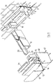
- Figure 1 is a perspective representation of the assembly of the profiles for the erection of a construction according to the invention.
- Figure 2 is a representation of a vertical section of the profiles assembled according to the invention between two bearing profiles.
- Figure 3 is a perspective representation of a connecting element according to the invention.
- Figure 4 is a cross section of the area tubular connection element according to the invention.
- Figure 5 is a cross section of a carrier profile.
- Figure 6 is a cross section of a connection of a bearing profile to a masonry profile.
- Figure 7 is a cross section of a sliding profile.
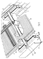
- Figure 8 is a perspective representation of the finish of a construction according to the invention.
- Figure 9 is a section through a cover profile.
- Figure 10 is a section through a curtain profile.
- Figure 11 is a perspective representation of a variant of a connecting element according to the invention.
- Figures 12 and 13 are representations of a vertical section of the profiles assembled in a construction according to the invention in an alternative embodiment, where one is not required to a given roof slope, while Figure 12 is drawn for a slight slope and Figure 13 for a greater slope (A section of the bearing profile and the sliding profile is shown in dotted lines in the cross section illustrated in fig.12 and 13).
- Figure 14 is a cross section of a cover piece.
- the masonry profile (1) (fig. 2 and 6) is composed of different parts; there is a flat surface (4) which lies along the wall and is divided into more or less two parts; a U-shaped upper part (5) with two wings (6) and (7) lie crosswise on the flat part (4) - and a lower box part (8) with a continuous groove (9) which extends in the direction of the length of the veranda, and in which cables, pipes, etc. can be slid.
- the supporting profile, or first profiled construction element (10) (fig. 5) is fixed to another second profiled construction element, angle (12) which is itself fixed to a column of support or which includes, in the longitudinal direction, a supporting infrastructure, e.g. by means of taps and screws.
- This angle (12) (fig.
- connection element (18) (FIGS. 3 and 4) according to the invention.
- This connecting element (18) is characterized by a tubular zone (19) (fig. 3) of rectangular cross section in the embodiment described which fits entirely into the tubular zone (11) of the carrier (10), is introduced into the hose and is attached to it.
- This tubular zone (19) of the connecting element (18) ends in a plate (20) provided at its top with a profiled part (21) which extends over the width of the plate (20), is itself provided with a U-shaped notch (22) and ends at the bottom with a semi-round edge (23) complementary either with the groove (9) of the masonry profile (1), or with the groove (16) of the angle iron (13).
- a connecting element (18) is placed at the intended distance from the masonry profile, so that the edge half-round (23) of the connecting element (18) can rest in the groove (9) of the box part (8) of the masonry profile (1) and the lower part of the closure plate (20) of the connecting element against the outside of the box part (8) of the masonry profile (1).
- the tubular area (19) of the connecting element is slid into a carrier profile (10).
- two guide notches (24) (fig. 3 and 4) are provided above and a central guide notch below (25); these notches correspond respectively above with the inner ribs (26) and below, with the inner ribs (27) of the box part (11) of the bearing profile (10).
- a sliding profile (28) (fig. 7) in the shape of an inverted T, the legs (29) of which can rest on the tubular part (11) of the support profile (10 ), being located below the profiled projections (17), by sliding the sliding profile (28) between these sailies (17). While the carrier profile (10) is slid up against the edge of the cover plate (20) of the connection element (18), the sliding profile (28) goes up to the masonry profile (1).
- the sliding profile (28) is also provided with two parallel guide notches (30), one on each leg (29), which correspond exactly with the upper guide ribs (26) of the tubular part (11) of the bearing profile ( 10) and with the upper parallel notches (24) of the tubular part (19) of the connection element (18), so that the three parts, sliding profile (28), bearing profile (10) and element connection (18), can be fixed together in the right place by screws or other fixing means.
- the roof is then sealed by means of sealing strips (43) of resilient material, cut to length, provided below in the middle of a rib (44) which is pressed into the groove (45) provided at this effect above the web of the sliding profiles (28), so that the wings of these sealing strips press against the top of the translucent panels (41) so as to seal the roof covering.
- cover slats (31) are slid along the masonry profile (1) and the angle iron (12) between two connecting elements (18) provided with bearing profiles (10) .
- These cover slats (31) are U-shaped, the core (32) of which is respectively parallel to the outer side of the lower part (8) of the masonry profile (1) or to the outer side of the lower box part.
- a groove (35) is also provided, as in the bearing profile (10); a sealing strip of resilient material can be introduced therein by driving in a rib with which this sealing strip is provided, in the groove in question (35), while the free wing of this sealing strip bears against the top of the translucent panels along the masonry profile or the angle, so that the waterproofing of the roof of the roof continues to be insured.
- the finish of verandas and similar constructions can be refined, for example by means of a profile for curtains (36) (fig. 10) of which, on the one hand, one end has the shape of a curtain rail in which the curtain hanging rollers can slide, and of which, on the other hand , the other end is provided with a double rib (38) making it possible to fix the curtain profile (36) to the angle iron (12) by sliding this rib (38) in the groove (39) below against the part in a box (15) of this angle (12).
- a profile for curtains (36) (fig. 10) of which, on the one hand, one end has the shape of a curtain rail in which the curtain hanging rollers can slide, and of which, on the other hand , the other end is provided with a double rib (38) making it possible to fix the curtain profile (36) to the angle iron (12) by sliding this rib (38) in the groove (39) below against the part in a box (15) of this angle (12).
- a connecting element (18 '), as shown in Figure 11, meets the characteristics of the coupling element according to the invention.
- the embodiment is however somewhat different from the fact that the profiled part (21 ') has the shape of a dovetail.
- the masonry profiles, angles, sliding profiles and other elements used are therefore adapted to this profiled part (21 ').
- tubular parts of the profiles may, for example, have partially or entirely a cylindrical shape instead of the parallelepiped shape, without however departing from the protection of the profiles and constructions according to the invention.
- a first drawback is the formation of condensation inside the various building elements, and mainly when these are made of metal, such as aluminum.
- the cause of this problem lies in the fact that different construction elements are in contact, on the one hand, with the open air and on the other hand, with the air inside the construction which actually has a temperature higher.
- Other construction elements which are only in contact with the open air are directly connected - without any break - to construction elements which are in contact with the air inside the construction.
- the construction elements or parts of construction elements which are in contact with the warmer air inside the construction have, thanks to their good thermal conductivity, a substantially lower temperature. to the air around them. Such a situation gives rise to the formation of condensation moisture on these building elements.
- a second drawback is that due to the shape of the various construction elements, and in particular the masonry profiles (1) and the angles (12), it is necessary to respect a fixed slope for the load-bearing profiles (10) which are find between these masonry profiles and the angles (12), and consequently, a fixed slope of the roof.
- a fixed slope of the roof has, on the one hand, the disadvantage that the person carrying out the construction is not free to fix the slope of the roof himself and on the other hand, that great precision is required at the time of construction, which is not easy, especially for the handyman.
- the problem of the fixed slope of the roof is solved by fixing at least one second profiled building element (52), (90) to a wall (3), or to a support frame which can rotate around an axis. roughly parallel to the longitudinal axis of the building element (52), (90).
- the possibility of rotation of at least one second profiled building element (52), (90) means that the slope of the first profiled building elements (10) connected thereto is not fixed. This slope can be adjusted - within certain limits - as desired or as a function of the required mounting height of a second profiled construction element (52), (90), to which these same first construction elements (10) are connected by the other extremity. These first construction elements (10) thus serve as support for the roof panels (41).
- a particularly advantageous embodiment is therefore characterized in that at least one second profiled construction element (52) fixed so that it can rotate is connected by means of a connection element (18) to one end of the first profiled building element (10), while the other end of this first profiled building element (10) is connected by means of a connecting element (18) to a another second rotating profiled building element (90), so that the two second profiled building elements (52) and (90) are fixed at a given horizontal distance from each other.
- the slope of the roof can be adjusted within certain limits (for example, between 5 ° and 20 ° relative to the horizontal), since the said second construction elements (52), (90) can all two be placed in a position where connection can best be effected with the connection elements located below the desired slope angle (18) - which are slid into the first connection elements
- At least one second profiled construction element (52), (90) is produced with a box part (60, (91) in the longitudinal direction, which is provided on the wall outer, of a rounded projecting edge (61), (92), of a shape complementary with the shape of a concave part (58), (74) of a profile (51), (70) which is attached to the wall (3) or to the support structure, and at least one second profiled construction element (52), (90) is rotatably connected to a firmly fixed profile (51), (70) because the edge (61), (92) can rotate in the concave part (58), (74).
- the problem of condensation is solved by providing thermal breaks between the elements which are in contact with the open air and the construction elements which are in contact with the air in the erected construction.
- a spacer (49) i.e. a strip of rectangular shape made of a material which is a poor conductor of heat, is held against the wall (3) between the two profiles (50) and (51), of the fact that respectively the upper or lower edge of this spacer (49) is respectively in the free space between the wall (3) and a lower projecting part (54) of the profile (50), or in the free space between the wall (3) and a projecting upper part (55) of the profile (51).
- closure piece (100) is also advantageous to fix a closure piece (100) on top of a firmly fixed profile (70), above which the roof panels (41) stretch, while said closure piece (100) is made of a material which is a poor conductor of heat in order to obtain, here too, a thermal break.
- the variant embodiment according to the invention consists of three profiles (50), (51), (52) (cf. FIGS. 12 and 13) provided in place of the masonry profile (1) described above.
- the first profile (50) has a flat wall (48) and a front wing forming an angle (53).
- the flat wall (48) ends at the bottom by a projecting part (54) parallel to the wall (48).
- This part (50) is fixed with its flat wall (48) against the wall (3) and advances at least partially above the construction. Between the wall (3) and the projecting lower part (54), there is a free space.
- the second profile (51) is fixed to the wall (3) of a roughly parallel, at a certain distance below the first profile (50) and ends at the top with a projecting part (55) which is parallel to the flat wall (56) by which it is fixed to the wall (3).
- the second profile (51) is also provided, at the bottom, with a forward extending wing (57) overhung by a profiled part in the shape of a gutter (58). Between the wall (3) and the projecting part (55) of this second profile (51), there is also a free space.
- a spacer (49) of roughly rectangular shape is placed, the upper edge of which is retained in the free space between the wall (3) and the part in projection (54) of the profile (50) and the lower edge in the free space between the wall (3) and the projecting part (55) of the profile (51).
- the third profile (52) consists of a box part (60) with on the upper surface, a groove (60 ') for receiving an edge (23) of a connection element (18) according to the invention.
- On the upper surface there is also an upright wall (62) ending in a groove (63) identical to that of the wing (7) of the upper part of the masonry profile (1) in the embodiment described.
- the third profile (52) has a box part (60) with an upper part whose front and rear walls are approximately parallel in the longitudinal direction of the profile (52) and with a lower part who is more narrower than the upper part because the rear wall - oriented towards the wall (3) - has a re-entrant part - towards the front wall - while the front wall continues downwards.
- the edge (61) is formed in the extension of the upper part of the rear wall and is therefore, opposite the narrower part of the box part (60), sufficient space still remains between the edge (61) and the re-entrant lower part of the lower wall of the box part (60), so that one leg of the gutter-shaped part (58) can be there.
- the edge (61) has, more particularly, a hook-shaped cross section.
- the second profile (51) and the third profile (52) are coupled together by placing the edge (61) in the gutter-shaped part (58).
- a leg is then in the gutter-shaped part (58) in the free space between the edge (61) and the re-entrant rear wall of the box part ( 60).
- the length of this leg of the gutter-shaped part (58) and the height of said free space are such that the third profile (52) can rotate relative to the second profile (51).
- the variant embodiment according to the invention also consists of two different profiles (70), (90) provided in place of the angle iron (12) described above.
- the first profile (70) consists of a U-shaped profile (72) extending in the longitudinal direction, while the wall (71) of this gutter (72) oriented towards the construction is formed by the wall of a box part (73). At the top of this box part (73), a groove (76) is provided for fixing a closure piece of elastic material (100) described below.
- the bottom of the gutter (72) is flat and rests on a wall or a support structure (for example, a frame).
- the bottom of said box part (73) is also flat, but is above the level of the lower side of the gutter (72), so that a free space is formed between the bottom of the box part ( 73) and the top of the wall or support structure.
- the rear wall of the box part (73) oriented towards the construction has a concave part (74), the bottom of which is formed by a rib (75) situated in the extension of the bottom of the box part (73).
- a complementary element of this alternative embodiment consists of a plastic profile (80) with a flat bottom wall (81) which fits in the free space between the wall or the support surface and the bottom of the part in box (73).
- the profile also has an upwardly directed lip (82) which ends in a concave part (83) complementary to the concave surface (74) in the wall of the box part (73).
- the wall (81) of the plastic profile (80) is placed below the box part (73), so that the concave part (83) is located in the concave part (74) of the box part (73).
- the second profile (90) consists of a box part (91) in the longitudinal direction with a roughly rectangular cross section.
- the upper surface of this box part (91) is provided with a groove (95) in the longitudinal direction intended to receive a connection element (18) according to the invention.
- a rib (93) is provided ending in a rounded edge (92) and approximately perpendicular to the front wall in question.
- This rounded edge (92) has a shape complementary to the shape of the concave part (83) of the profile in plastic (80) and will preferably have a hook-shaped cross section.
- This second profile (90) is connected to the first profile (70) by placing the edge (92) in the concave part (83) of the plastic profile (80), while this plastic profile (80) is located as described below. above relative to the first profile (70). The second profile (90) can therefore rotate relative to the first profile (70).
- a closure piece (100) of elastic material is fixed in the groove (76) of the first profile (70) (cf. FIG. 14).
- This closure part (100) is an oblong strip having two hollow parts (101), (102) superimposed. At the bottom of the first hollow part (101), there is provided a rib (103) having locally enlargements (104), so that thanks to the deformation of these enlargements, the latter can be inserted below narrowing of the groove. (76) and the rib (103) thus remains blocked there.
- the top of the closure piece (100) is deformed by the roof panels (41), so that a tight seal is formed.
- This closure part (100) also ensures thermal break.
Landscapes
- Engineering & Computer Science (AREA)
- Architecture (AREA)
- Civil Engineering (AREA)
- Structural Engineering (AREA)
- Physics & Mathematics (AREA)
- Electromagnetism (AREA)
- Joining Of Building Structures In Genera (AREA)
- Roof Covering Using Slabs Or Stiff Sheets (AREA)
- Tents Or Canopies (AREA)
- Accessories Of Cameras (AREA)
Claims (18)
- Konstruktion mit einem ersten Profilbauelement (10), das mit einem offenen rohrförmigen Teil (11) versehen ist, sowie mit einem zweiten Profilbauelement (1, 12), wobei diese Profilbauelemente (10; 1, 12) mittels eines Anschlußelements (18) gekoppelt sind, das einen rohrförmigen Teil (19) aufweist, von dem ein Ende durch eine flache Wand (20) geschlossen ist, an der sich ein Profilteil (21) befindet, der sich in Breitenrichtung dieser Wand (20) erstreckt und mit einem abgerundeten Rand (23) versehen ist, wobei das erste Bauelement bzw. Konstruktionselement (10) und das Anschlußelement (18) dadurch gekoppelt sind, daß der rohrförmige Teil (19) des Anschlußelements (18) derart in den offenen rohrförmigen Teil (11) des ersten Konstruktionselements (10) geschoben ist, daß der Profilteil (21) nach außen vorrückt, dadurch gekennzeichnet, daß das Anschlußelement (18) und das zweite Konstruktionselement (1, 12) dadurch gekoppelt sind, daß sich der abgerundete Rand (23) des Anschlußelements (18) in einer Nut (9, 16) mit komplementärer Form befindet, die an einer oberen Fläche des zweiten Konstruktionselements (1, 12) vorgesehen ist, wobei sich diese Nut (9, 16) im wesentlichen in Längsrichtung dieses Konstruktionselements (1, 12) erstreckt und nach oben offen ist.
- Konstruktion nach Anspruch 1, dadurch gekennzeichnet, daß das zweite Profilbauelement (1, 12) einen Kastenteil (8, 15) aufweist, der sich in Längsrichtung dieses Konstruktionselements erstreckt, und daß die Nut (9, 16) an einer oberen Fläche des Kastenteils (8, 15) vorgesehen ist.
- Konstruktion nach Anspruch 1 oder 2, dadurch gekennzeichnet, daß der abgerundete Rand (23) und die Nut (9, 16) eine im wesentlichen halbzylindrische Form aufweisen.
- Konstruktion nach einem der Ansprüche 1 bis 3, dadurch gekennzeichnet, daß der rohrförmige Teil (19) des Anschlußelements (18) an seiner Außenfläche mit wenigstens einer Führungskerbe (24, 25) versehen ist, die sich in Längsrichtung erstreckt, daß der offene rohrförmige Teil (11) des ersten Konstruktionselements (10) an seiner Innenfläche wenigstens eine Führungsrippe (26, 27) aufweist, die sich in Längsrichtung erstreckt und sich in der Führungskerbe (24, 25) des Anschlußelements (18) befindet.
- Konstruktion nach einem der Ansprüche 2 bis 4, dadurch gekennzeichnet, daß der untere Teil der flachen Wand (20) des Anschlußelements (18) gegen eine Flachseite des Kastenteils (8, 15) des zweiten Konstruktionselements (1, 12) anliegt.
- Konstruktion nach einem der vorhergehenden Ansprüche, dadurch gekennzeichnet, daß sie wenigstens eine Stützstruktur (3), ein zweites, an der Stützstruktur (3) befestigtes Konstruktionselement (1), ein weiteres zweites Konstruktionselement (2), das an einer weiteren Stützstruktur befestigt ist, sowie ein erstes Konstruktionselement (10) aufweist, dessen zwei Enden mit dem zweiten Konstruktionselement (1) bzw. mit dem anderen zweiten Konstruktionselement (12) gekoppelt sind.
- Konstruktion nach einem der vorhergehenden Ansprüche, dadurch gekennzeichnet, daß sie wenigstens eine U-förmige Profildeckleiste (31) mit einem oberen Flügel (34) und einem unteren Flügel (33) aufweist, deren Unterteil eine zur Nut (9, 16) eines zweiten Konstruktionselements (1, 12) komplementäre Form aufweist, wobei die Decklatte (31) mit dem Unterteil des unteren Flügels (33) in einem Teil der Nut (9, 16) angeordnet ist, der nicht von einem Rand (23) eines Anschlußelements (18) belegt ist, während der obere Flügel (34) über die gesamte Länge an das zweite Konstruktionselement (1, 12) angeschlossen ist.
- Konstruktion nach einem der vorhergehenden Ansprüche, dadurch gekennzeichnet, daß wenigstens ein erstes Konstruktionselement (10) an seiner oberen Fläche mit zwei im wesentlichen parallelen Vorsprüngen (17) mit zueinander orientierten Armen aufweist, daß die Konstruktion ein Gleitprofil (28) mit einem Querschnitt in Form eines umgedrehten T aufweist, und daß das Gleitprofil (28) auf die obere Fläche des ersten Konstruktionselements (10) geschoben ist, wobei sich seine Schenkel (29) seitlich unter die Arme der Vorsprünge (17) erstrecken, wobei sich das Gleitprofil (28) in Längsrichtung bis über wenigstens ein zweites Konstruktionselement (1, 12) erstreckt.
- Konstruktion nach einem der Ansprüche 4 und 8, dadurch gekennzeichnet, daß jeder Schenkel (29) wenigstns eines Gleitprofils (28) an der oberen Fläche eine Führungskerbe (30) besitzt, die sich in Längsrichtung des Gleitprofils (28) über den entsprechenden Führungsrippen (26) des ersten Konstruktionselements (10) erstreckt.
- Konstruktion nach einem der vorhergehenden Ansprüche, dadurch gekennzeichnet, daß die Konstruktion mehrere erste Konstruktionselemente (10), wenigstens zwei an diesen Konstruktionselementen angeordnete Dachelemente (41) sowie wenigstens ein Band (43) entweder zum Halten der Dachelemente (41) oder zum Gewährleisten der Abdichtung des Spalts zwischen zwei aneinandergrenzenden Dachelementen (41) aufweist, und daß wenigstens eines der verwendeten ersten Konstruktionselemente (10), der Decklatten (31) und der Gleitprofile (28) oben mit einer Nut (42 bzw. 35, 45) versehen ist, die eine Rippe (44) des Bandes (43) hält.
- Konstruktion nach einem der vorhergehenden Ansprüche, dadurch gekennzeichnet, daß wenigstens ein zweites Konstruktionselement (52, 90) derart an der Stützstruktur befestigt ist, daß es eine Drehung um eine Achse durchführen kann, die im wesentlichen parallel zur Längsachse des zweiten Konstruktionselements (52, 90) liegt.
- Konstruktion nach Anspruch 11, dadurch gekennzeichnet, daß sie wenigstens zwei zweite Konstruktionselemente (52, 90) aufweist, die in einem bestimmten horizontalen Abstand voneinander jeweils an einer unterschiedlichen Stützstruktur (3) befestigt sind, und daß jedes zweite Konstruktionselement (52, 90) durch ein Anschlußelement (18) an ein entsprechendes Ende eines ersten Konstruktionselements (10) angeschlossen ist.
- Konstruktion nach Anspruch 11 oder 12, dadurch gekennzeichnet, daß sie wenigstens ein zweites Profilbauelement (52, 90) mit einem Kastenteil (60, 91), der sich in Längsrichtung dieses Konstruktionselements erstreckt, einen abgerundeten Rand (61, 92) aufweist, der an einer Außenwand des Kastenteils (60, 91) vorsteht und eine zu dem konkaven Teil (58, 74) eines dritten Profilbauelements (51, 70) komplementäre Form aufweist, das fest an der Stützstruktur (3) befestigt ist, und daß wenigstens ein zweites Profilbauelement (52, 90) zur Durchführung einer Drehung dadurch an das dritte Bauelement angeschlossen ist, daß sich der Rand (61, 92) derart in dem konkaven Teil (58, 74) befindet, daß eine Drehung durchgeführt werden kann.
- Konstruktion nach Anspruch 13, dadurch gekennzeichnet, daß sie ein Profil (50) aufweist, das im wesentlichen horizontal über dem dritten Konstruktionselement (51, 70) an der Stützstruktur (3) befestigt ist, und daß ein Band (49) aus einem schlecht wärmeleitenden Material zwischen dem dritten Konstruktionselement (51) und dem Profil (50) gegen die Stützstruktur (3) gehalten sind.
- Konstruktion nach Anspruch 13 oder 14, dadurch gekennzeichnet, daß das dritte Profilbauelement (70) eine U-förmige Dachrinne (72), die sich in Längsrichtung dieses Konstruktionselements (70) erstreckt, sowie einen Kastenteil (73) aufweist, von dem eine Wand (71) die seitlich aufgerichtete Wand der Dachrinne (72) bildet, und von dem die entgegengesetzte Wand den konkaven Teil (74) bildet.
- Konstruktion nach einem der Ansprüche 13 bis 15, dadurch gekennzeichnet, daß sie ein mit einer Lippe (82) versehenes Profil (80) mit einem konkaven Teil (83) aufweist, der in dem konkaven Teil (74) des dritten Konstruktionselements (70) angeordnet ist, und daß der konkave Teil (83) des Profils (80) eine thermische Unterbrechung zwischen dem dritten Konstruktionselement (70) und dem abgerundeten Rand (92) eines zweiten Konstruktionselements (90) bildet, der sich in dem konkaven Teil (83) des Profils (80) befindet.
- Konstruktion nach einem der Ansprüche 13 bis 16, dadurch gekennzeichnet, daß sie ein von einem ersten Konstruktionselement (10) abgestütztes Dachelement (41) aufweist, dessen zwei Enden an ein zweites Konstruktionselement (52 bzw. 90) angeschlossen sind, und daß wenigstens eines dieser zweiten Konstruktionselemente (52, 90) an ein drittes Konstruktionselement (70) angeschlossen ist, von dem ein oberer Teil mit einer Nut (76) versehen ist, und daß die Konstruktion ein Abschlußstück (100) aus einem schlecht wärmeleitenden Material aufweist, das durch eine untere Rippe (103) in der Nut (76) gehalten wird; und daß das Abschlußstück (100) das Dachelement (41) oder das erste Konstruktionselement (10) berührt, das über dieses Abschlußstück (100) hängt.
- Konstruktion nach einem der vorhergehenden Ansprüche, dadurch gekennzeichnet, daß sie eine Veranda, ein Wintergarten oder eine ähnliche Konstruktion ist.
Applications Claiming Priority (2)
| Application Number | Priority Date | Filing Date | Title |
|---|---|---|---|
| BE9200223A BE1005740A5 (nl) | 1992-03-05 | 1992-03-05 | Koppelstuk voor bouwprofielen en veranda's, wintertuinen en dergelijke constructies, ermede uitgerust. |
| BE9200223 | 1992-03-05 |
Publications (2)
| Publication Number | Publication Date |
|---|---|
| EP0559292A1 EP0559292A1 (de) | 1993-09-08 |
| EP0559292B1 true EP0559292B1 (de) | 1997-04-16 |
Family
ID=3886174
Family Applications (1)
| Application Number | Title | Priority Date | Filing Date |
|---|---|---|---|
| EP93200640A Expired - Lifetime EP0559292B1 (de) | 1992-03-05 | 1993-03-05 | Anschlusselement für Bauprofile und Konstruktionen, die mittels solcher Anschlusselemente verbundene Bauprofile enthalten |
Country Status (4)
| Country | Link |
|---|---|
| EP (1) | EP0559292B1 (de) |
| AT (1) | ATE151837T1 (de) |
| BE (1) | BE1005740A5 (de) |
| DE (1) | DE69309756T2 (de) |
Families Citing this family (12)
| Publication number | Priority date | Publication date | Assignee | Title |
|---|---|---|---|---|
| FR2757891B1 (fr) * | 1996-12-27 | 1999-02-19 | Alcan France | Dispositif d'assemblage de profiles de structure notamment pour toiture de veranda ou analogue |
| BE1011100A5 (nl) * | 1997-04-11 | 1999-04-06 | Reynaers Int Nv | Verbeterde liggerbevestiging en bevestigingselementen hierbij gebruikt. |
| GB9805231D0 (en) * | 1998-03-12 | 1998-05-06 | Ultraframe Plc | Portals |
| GB9806208D0 (en) * | 1998-03-24 | 1998-05-20 | Rickmans Limited | Conservatory roof construction |
| GB9906085D0 (en) | 1999-03-18 | 1999-05-12 | Ultraframe Uk Ltd | Roof construction |
| GB0000129D0 (en) * | 2000-01-06 | 2000-02-23 | Whiting Richard A | Components for roof assemblies |
| FR2816340B1 (fr) * | 2000-11-06 | 2004-01-09 | Technal | Dispositif d'assemblage de profiles de structure de toiture, en particulier de verriere, a multiple degres de liberte de position |
| FR2852039B1 (fr) * | 2003-03-03 | 2005-04-08 | Technal | Dispositif pour solidariser un chevron d'un profile |
| DE10329717A1 (de) * | 2003-07-02 | 2005-01-27 | BTW GmbH Brandschutztüren und Brandschutzwände | Freistanddach |
| GB2538540B (en) * | 2015-05-20 | 2020-02-05 | Leka Systems Ltd | Roof structure for a single storey extension |
| PL3290612T3 (pl) * | 2016-08-29 | 2019-12-31 | Ingo Kneer | Urządzenie do pokrycia dachowego i sposób wytwarzania urządzenia do pokrycia dachowego |
| PL3412844T3 (pl) * | 2017-06-08 | 2020-07-13 | Ingo Kneer | Zespół mocowania rynny dachowej, układ dachowy i sposób montażu rynny dachowej |
Family Cites Families (6)
| Publication number | Priority date | Publication date | Assignee | Title |
|---|---|---|---|---|
| FR1380979A (fr) * | 1963-02-11 | 1964-12-04 | Serrenbouw Deforche P V B A | Profilés perfectionnés de liaison pour l'assemblage de serres, hangars, vérandas et constructions semblables |
| US3837128A (en) * | 1972-10-24 | 1974-09-24 | Fleury T | Partitioning system |
| BE880709A (nl) * | 1979-12-19 | 1980-06-19 | Frans Crollet En Zonen P V B A | Verbeterde bevestiging tussen nokprofiel en glasroeden bij serres |
| FR2533605A1 (fr) * | 1982-09-24 | 1984-03-30 | Dubois Claude | Liaison entre chevrons et cheneau dans une structure de veranda |
| FR2653836B1 (fr) * | 1989-10-27 | 1992-03-06 | Lefur Jean Paul | Systeme d'assemblage de profiles creux et structure portante obtenue. |
| DE4019109A1 (de) * | 1990-06-15 | 1991-12-19 | Schweers Hans Gerd Dipl Ing | Holzkonstruktion, insbesondere fuer das dach eines wintergartens |
-
1992
- 1992-03-05 BE BE9200223A patent/BE1005740A5/nl not_active IP Right Cessation
-
1993
- 1993-03-05 DE DE69309756T patent/DE69309756T2/de not_active Expired - Fee Related
- 1993-03-05 EP EP93200640A patent/EP0559292B1/de not_active Expired - Lifetime
- 1993-03-05 AT AT93200640T patent/ATE151837T1/de not_active IP Right Cessation
Also Published As
| Publication number | Publication date |
|---|---|
| DE69309756T2 (de) | 1997-08-21 |
| DE69309756D1 (de) | 1997-05-22 |
| EP0559292A1 (de) | 1993-09-08 |
| ATE151837T1 (de) | 1997-05-15 |
| BE1005740A5 (nl) | 1994-01-11 |
Similar Documents
| Publication | Publication Date | Title |
|---|---|---|
| EP0559292B1 (de) | Anschlusselement für Bauprofile und Konstruktionen, die mittels solcher Anschlusselemente verbundene Bauprofile enthalten | |
| CH621189A5 (de) | ||
| FR2948394A1 (fr) | Poutre pour l'adossement d'une structure d'abri a un element de construction et abri adossable obtenu | |
| FR3088659A1 (fr) | Protection solaire | |
| FR3028539A1 (fr) | Lame orientable pour toiture exterieure et un dispositif de toiture exterieure muni desdites lames | |
| OA12829A (fr) | Dispositif de toiture à lames avec aération. | |
| EP1964990A1 (de) | Winkelelement für teleskopierenden Unterstand | |
| EP3673121B1 (de) | Abdeckvorrichtung mit beweglichen platten, insbesondere für eine pergola | |
| FR2528103A1 (fr) | Toiture de veranda et chassis modulaire pour sa realisation | |
| FR2948723A1 (fr) | Dispositif de drainage pour seuil de chassis de fermeture coulissant | |
| EP1564337B1 (de) | Modul für modulare Baustruktur | |
| EP2103756A2 (de) | Sonnenschutzstruktur | |
| EP1024232B1 (de) | Deckenplatte | |
| FR2655676A1 (fr) | Toiture isolante a chevrons metalliques. | |
| FR3094021A1 (fr) | Closoir ventilé pour toiture | |
| EP0473565B1 (de) | Dachfenster | |
| FR2522357A1 (fr) | Lame de volet roulant | |
| FR2904018A1 (fr) | Construction ventilee | |
| FR2691195A1 (fr) | Perfectionnement au faîtage de constructions du genre vérandas, piscines, spas ou autres. | |
| EP0155243A2 (de) | Gruppe von Elementen zum Herstellen leichter Bedachungen, insbesondere von Verandas | |
| FR2893961A1 (fr) | Abri a troncons mobiles. | |
| FR2489395A1 (fr) | Element autoportant pour une toiture de batiment, son procede de fabrication et installation pour la mise en oeuvre dudit procede | |
| FR2570403A1 (fr) | Structure de batiments incorporant des elements, porteurs notamment, en tole galvanisee pliee | |
| EP0983408A1 (de) | Abdeckelement | |
| FR2491599A1 (fr) | Capteur solaire utilisant l'air comme fluide caloporteur, et ses composants |
Legal Events
| Date | Code | Title | Description |
|---|---|---|---|
| PUAI | Public reference made under article 153(3) epc to a published international application that has entered the european phase |
Free format text: ORIGINAL CODE: 0009012 |
|
| AK | Designated contracting states |
Kind code of ref document: A1 Designated state(s): AT BE CH DE FR GB IT LI NL |
|
| 17P | Request for examination filed |
Effective date: 19930915 |
|
| RIN1 | Information on inventor provided before grant (corrected) |
Inventor name: BLOMME, JOHAN |
|
| 17Q | First examination report despatched |
Effective date: 19951025 |
|
| GRAG | Despatch of communication of intention to grant |
Free format text: ORIGINAL CODE: EPIDOS AGRA |
|
| GRAH | Despatch of communication of intention to grant a patent |
Free format text: ORIGINAL CODE: EPIDOS IGRA |
|
| GRAH | Despatch of communication of intention to grant a patent |
Free format text: ORIGINAL CODE: EPIDOS IGRA |
|
| GRAA | (expected) grant |
Free format text: ORIGINAL CODE: 0009210 |
|
| AK | Designated contracting states |
Kind code of ref document: B1 Designated state(s): AT BE CH DE FR GB IT LI NL |
|
| PG25 | Lapsed in a contracting state [announced via postgrant information from national office to epo] |
Ref country code: IT Free format text: LAPSE BECAUSE OF FAILURE TO SUBMIT A TRANSLATION OF THE DESCRIPTION OR TO PAY THE FEE WITHIN THE PRESCRIBED TIME-LIMIT;WARNING: LAPSES OF ITALIAN PATENTS WITH EFFECTIVE DATE BEFORE 2007 MAY HAVE OCCURRED AT ANY TIME BEFORE 2007. THE CORRECT EFFECTIVE DATE MAY BE DIFFERENT FROM THE ONE RECORDED. Effective date: 19970416 Ref country code: GB Effective date: 19970416 Ref country code: AT Effective date: 19970416 |
|
| REF | Corresponds to: |
Ref document number: 151837 Country of ref document: AT Date of ref document: 19970515 Kind code of ref document: T |
|
| REG | Reference to a national code |
Ref country code: CH Ref legal event code: EP |
|
| REF | Corresponds to: |
Ref document number: 69309756 Country of ref document: DE Date of ref document: 19970522 |
|
| GBV | Gb: ep patent (uk) treated as always having been void in accordance with gb section 77(7)/1977 [no translation filed] |
Effective date: 19970416 |
|
| PLBE | No opposition filed within time limit |
Free format text: ORIGINAL CODE: 0009261 |
|
| STAA | Information on the status of an ep patent application or granted ep patent |
Free format text: STATUS: NO OPPOSITION FILED WITHIN TIME LIMIT |
|
| PG25 | Lapsed in a contracting state [announced via postgrant information from national office to epo] |
Ref country code: LI Free format text: LAPSE BECAUSE OF NON-PAYMENT OF DUE FEES Effective date: 19980331 Ref country code: CH Free format text: LAPSE BECAUSE OF NON-PAYMENT OF DUE FEES Effective date: 19980331 |
|
| 26N | No opposition filed | ||
| REG | Reference to a national code |
Ref country code: CH Ref legal event code: PL |
|
| PGFP | Annual fee paid to national office [announced via postgrant information from national office to epo] |
Ref country code: NL Payment date: 20080318 Year of fee payment: 16 |
|
| PGFP | Annual fee paid to national office [announced via postgrant information from national office to epo] |
Ref country code: FR Payment date: 20080314 Year of fee payment: 16 Ref country code: DE Payment date: 20080321 Year of fee payment: 16 |
|
| PGFP | Annual fee paid to national office [announced via postgrant information from national office to epo] |
Ref country code: BE Payment date: 20080430 Year of fee payment: 16 |
|
| BERE | Be: lapsed |
Owner name: *ALLAN THOMSON N.V. Effective date: 20090331 |
|
| NLV4 | Nl: lapsed or anulled due to non-payment of the annual fee |
Effective date: 20091001 |
|
| REG | Reference to a national code |
Ref country code: FR Ref legal event code: ST Effective date: 20091130 |
|
| PG25 | Lapsed in a contracting state [announced via postgrant information from national office to epo] |
Ref country code: DE Free format text: LAPSE BECAUSE OF NON-PAYMENT OF DUE FEES Effective date: 20091001 |
|
| PG25 | Lapsed in a contracting state [announced via postgrant information from national office to epo] |
Ref country code: NL Free format text: LAPSE BECAUSE OF NON-PAYMENT OF DUE FEES Effective date: 20091001 Ref country code: BE Free format text: LAPSE BECAUSE OF NON-PAYMENT OF DUE FEES Effective date: 20090331 |
|
| PG25 | Lapsed in a contracting state [announced via postgrant information from national office to epo] |
Ref country code: FR Free format text: LAPSE BECAUSE OF NON-PAYMENT OF DUE FEES Effective date: 20091123 |