EP0560007A1 - Languettes de stator de moteur électrique - Google Patents
Languettes de stator de moteur électrique Download PDFInfo
- Publication number
- EP0560007A1 EP0560007A1 EP93100171A EP93100171A EP0560007A1 EP 0560007 A1 EP0560007 A1 EP 0560007A1 EP 93100171 A EP93100171 A EP 93100171A EP 93100171 A EP93100171 A EP 93100171A EP 0560007 A1 EP0560007 A1 EP 0560007A1
- Authority
- EP
- European Patent Office
- Prior art keywords
- teeth
- stator
- electric motor
- tab
- bent
- Prior art date
- Legal status (The legal status is an assumption and is not a legal conclusion. Google has not performed a legal analysis and makes no representation as to the accuracy of the status listed.)
- Withdrawn
Links
Images


Classifications
-
- H—ELECTRICITY
- H02—GENERATION; CONVERSION OR DISTRIBUTION OF ELECTRIC POWER
- H02K—DYNAMO-ELECTRIC MACHINES
- H02K3/00—Details of windings
- H02K3/46—Fastening of windings on the stator or rotor structure
- H02K3/52—Fastening salient pole windings or connections thereto
- H02K3/521—Fastening salient pole windings or connections thereto applicable to stators only
- H02K3/522—Fastening salient pole windings or connections thereto applicable to stators only for generally annular cores with salient poles
-
- H—ELECTRICITY
- H02—GENERATION; CONVERSION OR DISTRIBUTION OF ELECTRIC POWER
- H02K—DYNAMO-ELECTRIC MACHINES
- H02K2203/00—Specific aspects not provided for in the other groups of this subclass relating to the windings
- H02K2203/06—Machines characterised by the wiring leads, i.e. conducting wires for connecting the winding terminations
Definitions
- the present invention relates to the technical field of electric motors utilizing a stator core made of a plurality of bound laminations. More specifically, the present invention relates to the construction of the laminated stator core so that wire extending between coils located on stator teeth can be retained away from the rotor.
- Stator cores are commonly now made of bound laminations which are punched or stamped out of flat magnetically permeable stock materials.
- the laminated stator cores of, for example, shaded pole and half-pitch capacitor induction motors include a plurality of teeth extending inwardly from a yoke portion and defining a bore whereat a rotor is received.
- Morrill, U.S. Patent No. 4,371,802 and U.S. Patent No. 4,649,305 show a stator core of a half-pitch capacitor induction motor wherein coils of wire are wrapped around the stator teeth. These coils are excited in a known and customary manner and provide the necessary flux for driving the rotor.
- Each of the stator core coils are normally wound by an automatic winding machine with a proper size and type of wire. So as to retain the wire away from the rotor and to extend from one coil to the next, Morrill, U.S. Patent No. 4,649,305 shows the use of a pin whereover the wire is passed. The pin shown therein appears above each stator tooth and wire extending to and from the coils extends thereover. This pin is apparently mechanically fastened or otherwise placed on the stator core member. Such placement of a pin, however, would require an additional manufacturing step thereby increasing time and material costs and, thereby, increasing the overall cost of the motor.
- stator core having the capabilities of retaining the wire away from the rotor as the wire extends from coil to coil and which is less time-consuming and less costly to manufacture.
- the present invention overcomes the disadvantages associated with prior stator cores by stamping or punching an end stator lamination that includes tab portions.
- the tabs which initially are in the same plane as the lamination are bent to extend away from the stator thereby providing a resting ledge whereat the wire extending from coil to coil may rest.
- the tabs are preferably located between the stator coil teeth so that the wire exiting one coil can more easily be directed thereover and to a next succeeding coil.
- the tab portion as initially punched has a rounded semi-circular end part for preventing potential snagging of the wire during the winding operation.
- the present invention is directed to an electric motor including a circular stator core having a plurality of angularly spaced radially inwardly extending teeth defining winding slots therebetween.
- the teeth have inner ends defining a bore and a plurality of wire coils are wrapped on the teeth.
- a rotor member is located in the bore.
- the stator is made of a plurality of bound laminations including an end lamination.
- the end lamination includes a tab portion bent to extend away from the stator.
- the wire extending between the coils extends over the tab portion and is retained away from the rotor.
- the present invention is directed to an electric motor including a circular stator core having a plurality of angularly spaced, radially inwardly extending teeth defining winding slots therebetween.
- the teeth have inner ends defining a bore and a plurality of wire coils are wrapped on the teeth.
- a rotor member is located in the bore.
- the stator is made of a plurality of bound laminations including an end lamination, and the end lamination includes a tab portion located between two stator teeth. The tab portion is bent to extend away from the stator and, also, is shaped having a rounded, semi-circular end part.
- the wire extending between the coils extends over the tab portion and is retained away from the rotor.
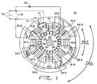
- Stator core member 12 includes a generally cylindrically-shaped yoke portion 14 and equally angularly spaced radially inwardly extending teeth 16 respectively defining winding slots 18 therebetween.
- Teeth 16 have inner ends 20 which define a bore for receiving laminated rotor member 22 on shaft 24.
- Outer periphery 26 of rotor member 22 defines radial air gaps 28 with inner ends 20 of stator teeth 16.
- Outer periphery 26 also has generally axially extending slots 30 formed therein for a squirrel cage winding 32 therein in a known and customary fashion.
- stator teeth 16 is twice the number of poles of motor 10 and, thus, in the embodiment shown in the figures, there are four poles and a total of eight stator teeth 16.
- the inner ends 20 of teeth 16 have substantially equal angular extent. That is, the pole face 31 of each tooth 16 embraces outer periphery 26 of rotor member 22 with the same span as every other tooth.
- a main field winding is provided including serially connected coils 34-1, 34-3, 34-5, and 34-7 respectively embracing teeth 16-1, 16-3, 16-5, and 16-7.
- the main field winding coils 34-1, 34-3, 34-5, and 34-7 are serially connected across single-phase alternating current source 36 such as 120 volts, 60 Hz.
- An auxiliary field winding is provided and includes coils 38-2, 38-4, 38-6 and 38-8 respectively embracing consecutive alternate teeth 16-2, 16-4, 16-6, and 16-8 intermediate the teeth upon which the main winding coils 34 are wound.
- Auxiliary field winding coils 38-2, 38-4, 38-6, and 38-8 are serially connected with phase shifting capacitor 40 across the serially connected main field winding coils 34 as indicated at 42.
- full pitch is the angular extent of one pole of motor 10, i.e., 90 degrees mechanical in the illustrated four pole embodiment
- half-pitch is the angular extent of one-half of one pole i.e., 45 degrees mechanical in the illustrated four pole embodiment.
- the magnetic flux crossing air gap 28 into or out of respective teeth ends 20 has a substantially half-pitch span.
- the stator core 12 is made of a plurality of bound laminations 60 including an end lamination 62.
- the laminations are bound together in a known and customary manner.
- Each of the laminations 60 and 62 are stamped from flat stock of magnetically permeable material prior to being assembled together.
- the end lamination 62 includes a plurality of tabs 66 whereby wire 67 extending between coils 34 and 38 is placed thereover and is thereby retained away from the rotor 22.
- Tabs 66 are stamped out along with the end lamination piece 62 and, thereafter, are bent at an angle extending away from the stator 12 as shown for providing a resting ledge 68 whereat the wire 67 rests.
- a single tab is provided between each of said coils 34.
- two or more tabs 66 can be provided between successive teeth 16.
- tabs 66 are bent in a plane substantially perpendicular to that of end lamination 62 for providing an effective resting ledge 68.
- tabs 66 may be bent at an obtuse or acute angle from the end lamination 62 as originally stamped.
- Each of tabs 66 are rounded with a semi-circular end part 72 as shown in the drawings. In this fashion, the potential for snagging and possibly damaging the wire as it is being wound on teeth 16 during production is decreased and, again, production costs are thereby decreased.
- tabs 66 can be located not only on the edges 74 of the end laminations 62 but, also, on the outer periphery edge 76. It is also contemplated that such tabs can be stamped out, for example, from the stator core 62 center area as needed. Further yet, depending on the winding process and wire 67 location, two end laminations 60 can be used, one on each side of stator core 12. In such an embodiment, tabs 66 retain wire away from rotor 22 on both sides of stator 12.
Landscapes
- Engineering & Computer Science (AREA)
- Power Engineering (AREA)
- Iron Core Of Rotating Electric Machines (AREA)
Applications Claiming Priority (2)
| Application Number | Priority Date | Filing Date | Title |
|---|---|---|---|
| US07/848,701 US5194775A (en) | 1992-03-09 | 1992-03-09 | Electric motor stator tabs |
| US848701 | 1992-03-09 |
Publications (1)
| Publication Number | Publication Date |
|---|---|
| EP0560007A1 true EP0560007A1 (fr) | 1993-09-15 |
Family
ID=25304043
Family Applications (1)
| Application Number | Title | Priority Date | Filing Date |
|---|---|---|---|
| EP93100171A Withdrawn EP0560007A1 (fr) | 1992-03-09 | 1993-01-08 | Languettes de stator de moteur électrique |
Country Status (4)
| Country | Link |
|---|---|
| US (1) | US5194775A (fr) |
| EP (1) | EP0560007A1 (fr) |
| AU (1) | AU653084B2 (fr) |
| CA (1) | CA2084007C (fr) |
Cited By (4)
| Publication number | Priority date | Publication date | Assignee | Title |
|---|---|---|---|---|
| EP1035631A3 (fr) * | 1993-11-08 | 2002-02-13 | Mitsubishi Denki Kabushiki Kaisha | Moteur rotatif et son procédé de fabrication, noyau feuilleté et son procédé de fabrication |
| EP1249920A3 (fr) * | 2001-04-09 | 2004-07-14 | Kabushiki Kaisha Moric | Stator de machine tournante électrique |
| EP1387465A3 (fr) * | 2002-07-30 | 2006-01-04 | Minebea Co., Ltd. | Dispositif de détente des contraintes du fils de bobinage de stator |
| US7567009B2 (en) | 2005-08-17 | 2009-07-28 | Minebea Co., Ltd. | Stator arrangement for an electric machine and a method for manufacturing the stator arrangement |
Families Citing this family (35)
| Publication number | Priority date | Publication date | Assignee | Title |
|---|---|---|---|---|
| US5306976A (en) * | 1993-01-29 | 1994-04-26 | General Electric Company | Motor and stationary assembly therefor having end caps and overlapping film slot insulation |
| US6121711A (en) * | 1993-11-08 | 2000-09-19 | Mitsubishi Denki Kabushiki Kaisha | Rotary motor and production method thereof, and laminated core and production method thereof |
| US5481144A (en) * | 1994-06-03 | 1996-01-02 | Seagate Technology, Inc. | Wire guide and adhesive retaining ring for disc drive spindle motor |
| DE19652490A1 (de) * | 1996-12-17 | 1998-06-18 | Philips Patentverwaltung | Magnetisches Getriebe |
| JP3790601B2 (ja) * | 1997-05-02 | 2006-06-28 | 日本電産サンキョー株式会社 | モータ |
| DE69820534T2 (de) * | 1997-05-14 | 2004-09-23 | Toyota Jidosha K.K., Toyota | Stator für einen Elektromotor |
| US6157109A (en) * | 1998-02-10 | 2000-12-05 | Reliance Electric Technologies, Llc | Dynamoelectric machine with ferromagnetic end winding ring |
| US6008560A (en) * | 1998-02-13 | 1999-12-28 | General Electric Company | Inverter driven motor having winding termination reducing EMI |
| JPH11332187A (ja) * | 1998-05-14 | 1999-11-30 | Sankyo Seiki Mfg Co Ltd | 誘導回転電機 |
| USD443585S1 (en) | 1999-01-25 | 2001-06-12 | Toshiba Carrier Corporation | Core for a stator |
| DE10005232C2 (de) * | 2000-02-05 | 2003-01-30 | Prec Motors Deutsche Minebea G | Spindelmotor für Festplatten mit höhenreduziertem Stator |
| AU2001276691A1 (en) * | 2000-08-03 | 2002-02-18 | Matsushita Electric Industrial Co., Ltd. | Brushless motor and method of manufacturing the brushless motor |
| US6487769B2 (en) | 2000-11-30 | 2002-12-03 | Emerson Electric Co. | Method and apparatus for constructing a segmented stator |
| US6597078B2 (en) | 2000-12-04 | 2003-07-22 | Emerson Electric Co. | Electric power steering system including a permanent magnet motor |
| US6700284B2 (en) | 2001-03-26 | 2004-03-02 | Emerson Electric Co. | Fan assembly including a segmented stator switched reluctance fan motor |
| US6744166B2 (en) | 2001-01-04 | 2004-06-01 | Emerson Electric Co. | End cap assembly for a switched reluctance electric machine |
| US7012350B2 (en) * | 2001-01-04 | 2006-03-14 | Emerson Electric Co. | Segmented stator switched reluctance machine |
| US6584813B2 (en) | 2001-03-26 | 2003-07-01 | Emerson Electric Co. | Washing machine including a segmented stator switched reluctance motor |
| US6897591B2 (en) | 2001-03-26 | 2005-05-24 | Emerson Electric Co. | Sensorless switched reluctance electric machine with segmented stator |
| JP2002315250A (ja) * | 2001-04-09 | 2002-10-25 | Moric Co Ltd | 回転電気機器のステータ |
| JP2003079079A (ja) * | 2001-09-03 | 2003-03-14 | Honda Motor Co Ltd | 回転電機の集配電リング |
| JP2003324886A (ja) * | 2002-04-30 | 2003-11-14 | Sankyo Seiki Mfg Co Ltd | モータ及びその製造方法 |
| KR100665119B1 (ko) * | 2005-02-21 | 2007-01-09 | 삼성전기주식회사 | 스테이터와 이를 갖는 전기모터 |
| EP1722464B1 (fr) * | 2005-05-11 | 2019-05-08 | Brose Fahrzeugteile GmbH & Co. KG, Würzburg | Méthode pour bobiner un stator de moteur électrique et stator de moteur électrique |
| JP2007060798A (ja) * | 2005-08-24 | 2007-03-08 | Nippon Densan Corp | モータの電機子、モータおよび記録ディスク駆動装置 |
| US7545069B2 (en) * | 2006-04-04 | 2009-06-09 | Ford Global Technologies, Llc | Electric machine winding arrangement |
| JP5150930B2 (ja) * | 2007-11-07 | 2013-02-27 | 本田技研工業株式会社 | アウタロータ型多極発電機 |
| TWM346978U (en) * | 2008-06-27 | 2008-12-11 | chao-xiong Lin | Triphase rotary electric power generator |
| JP5605997B2 (ja) * | 2009-03-05 | 2014-10-15 | 山洋電気株式会社 | 回転電機用ステータ |
| USD647478S1 (en) * | 2010-10-20 | 2011-10-25 | Johnson Electric S.A. | Rotor core for an electric motor |
| JP5391325B1 (ja) * | 2012-06-01 | 2014-01-15 | ファナック株式会社 | 電動機にコイルを固定するコイル固定装置、及び該コイル固定装置を備えた電動機 |
| US10193430B2 (en) | 2013-03-15 | 2019-01-29 | Board Of Trustees Of Michigan State University | Electromagnetic device having discrete wires |
| TWI581544B (zh) * | 2016-04-01 | 2017-05-01 | Built-in capacitive motor for improved construction | |
| USD1006753S1 (en) * | 2021-12-07 | 2023-12-05 | Mattur Holdings, Inc. | Stator |
| USD1001733S1 (en) * | 2021-12-07 | 2023-10-17 | Mattur Holdings, Inc. | Stator disk |
Citations (4)
| Publication number | Priority date | Publication date | Assignee | Title |
|---|---|---|---|---|
| FR1175284A (fr) * | 1956-06-30 | 1959-03-23 | Electrolux Ab | Dispositif d'isolation notamment pour bobinages |
| GB1415592A (en) * | 1973-01-25 | 1975-11-26 | Ass Elect Ind | Electric machines |
| DE3604939A1 (de) * | 1986-02-17 | 1987-08-20 | Licentia Gmbh | Auf die stirnseite des staenderblechpakets eines elektromotors mit ausgepraegten polen aufsetzbare endscheibe |
| DE9003916U1 (de) * | 1989-05-17 | 1990-09-06 | Zanussi Elettromeccanica S.P.A., Pordenone | Elektromotor |
Family Cites Families (10)
| Publication number | Priority date | Publication date | Assignee | Title |
|---|---|---|---|---|
| US565931A (en) * | 1896-08-18 | Armature-winding | ||
| DE482506C (de) * | 1921-07-09 | 1929-09-14 | Bbc Brown Boveri & Cie | Einrichtung zur kurzschlusssicheren Befestigung von evolventenfoermig ausgebildeten Staenderwicklungskoepfen luftgekuehlter elektrischer Maschinen |
| US2810848A (en) * | 1954-06-01 | 1957-10-22 | Bendix Aviat Corp | Method and means of making stator coil end turns |
| US2835453A (en) * | 1957-01-23 | 1958-05-20 | Sperry Rand Corp Ford Instr Co | Stator winder |
| CH398768A (de) * | 1961-11-13 | 1966-03-15 | Heemaf N V Aktiengesellschaft | Elektrische Maschine mit Luftkühlung und einem Staubabscheider |
| US3861026A (en) * | 1971-09-15 | 1975-01-21 | Gen Electric | Method of making dynamoelectric machines |
| US4371802A (en) * | 1980-06-12 | 1983-02-01 | Morrill Wayne J | Half-pitch capacitor induction motor |
| US4649305A (en) * | 1986-02-06 | 1987-03-10 | Morrill Wayne J | Capacitor between motor windings |
| US4959578A (en) * | 1987-11-24 | 1990-09-25 | Axial Electric, Inc. | Dual rotor axial air gap induction motor |
| US4864176A (en) * | 1988-07-29 | 1989-09-05 | Rem Technologies, Inc. | Stator support structure with stamped end plates |
-
1992
- 1992-03-09 US US07/848,701 patent/US5194775A/en not_active Expired - Lifetime
- 1992-11-24 AU AU29611/92A patent/AU653084B2/en not_active Ceased
- 1992-11-27 CA CA002084007A patent/CA2084007C/fr not_active Expired - Fee Related
-
1993
- 1993-01-08 EP EP93100171A patent/EP0560007A1/fr not_active Withdrawn
Patent Citations (4)
| Publication number | Priority date | Publication date | Assignee | Title |
|---|---|---|---|---|
| FR1175284A (fr) * | 1956-06-30 | 1959-03-23 | Electrolux Ab | Dispositif d'isolation notamment pour bobinages |
| GB1415592A (en) * | 1973-01-25 | 1975-11-26 | Ass Elect Ind | Electric machines |
| DE3604939A1 (de) * | 1986-02-17 | 1987-08-20 | Licentia Gmbh | Auf die stirnseite des staenderblechpakets eines elektromotors mit ausgepraegten polen aufsetzbare endscheibe |
| DE9003916U1 (de) * | 1989-05-17 | 1990-09-06 | Zanussi Elettromeccanica S.P.A., Pordenone | Elektromotor |
Cited By (4)
| Publication number | Priority date | Publication date | Assignee | Title |
|---|---|---|---|---|
| EP1035631A3 (fr) * | 1993-11-08 | 2002-02-13 | Mitsubishi Denki Kabushiki Kaisha | Moteur rotatif et son procédé de fabrication, noyau feuilleté et son procédé de fabrication |
| EP1249920A3 (fr) * | 2001-04-09 | 2004-07-14 | Kabushiki Kaisha Moric | Stator de machine tournante électrique |
| EP1387465A3 (fr) * | 2002-07-30 | 2006-01-04 | Minebea Co., Ltd. | Dispositif de détente des contraintes du fils de bobinage de stator |
| US7567009B2 (en) | 2005-08-17 | 2009-07-28 | Minebea Co., Ltd. | Stator arrangement for an electric machine and a method for manufacturing the stator arrangement |
Also Published As
| Publication number | Publication date |
|---|---|
| US5194775A (en) | 1993-03-16 |
| AU2961192A (en) | 1993-09-16 |
| AU653084B2 (en) | 1994-09-15 |
| CA2084007A1 (fr) | 1993-09-10 |
| CA2084007C (fr) | 1997-09-23 |
Similar Documents
| Publication | Publication Date | Title |
|---|---|---|
| US5194775A (en) | Electric motor stator tabs | |
| EP0564759B1 (fr) | Moteur asynchrone | |
| US4616151A (en) | Armature with quiet core construction | |
| US5877574A (en) | Dynamoelectric machine | |
| US5670836A (en) | Variable reluctance start permanent magnet motor | |
| US3956651A (en) | Wire stator structure | |
| EP0067114B1 (fr) | Moteur à induction à condensateur d'un demi-pas polaire | |
| US6462451B1 (en) | Permanent magnet rotating electric machine | |
| US3983435A (en) | Stator assembly formed of flat, strip material | |
| US4556811A (en) | Coil unit and coil form for electrical machines | |
| US5523637A (en) | Permanent magnet electrical machine with low reluctance torque | |
| US7049725B2 (en) | Dynamoelectric machine stator and method for mounting prewound coils thereunto | |
| EP0543625A2 (fr) | Machines dynamo-électriques à aimants permanents | |
| JP2004517597A (ja) | 電気機械のための構成エレメント | |
| US6043584A (en) | End turn phase insulator and method of using same | |
| US3983434A (en) | Segmented stator core structure and method for making same | |
| US4263524A (en) | Electric two motor drive | |
| USRE28705E (en) | Stator slot and winding arrangements | |
| WO2002047238A1 (fr) | Noyaux magnetiques de machines electriques | |
| WO2001095459A1 (fr) | Stator pour machine electrique | |
| US6560854B2 (en) | Coil-winding method for electric motor, generator and alternator | |
| US20050258702A1 (en) | Multiple winding coil shapes for increased slot fill | |
| EP0045125A1 (fr) | Stators pour moteurs électriques | |
| JPH10290545A (ja) | 回転電機のステータおよびステータの製造方法 | |
| JP3233945B2 (ja) | 爪形磁極機械 |
Legal Events
| Date | Code | Title | Description |
|---|---|---|---|
| PUAI | Public reference made under article 153(3) epc to a published international application that has entered the european phase |
Free format text: ORIGINAL CODE: 0009012 |
|
| AK | Designated contracting states |
Kind code of ref document: A1 Designated state(s): CH DE FR GB IT LI NL |
|
| 17P | Request for examination filed |
Effective date: 19940117 |
|
| 17Q | First examination report despatched |
Effective date: 19950126 |
|
| STAA | Information on the status of an ep patent application or granted ep patent |
Free format text: STATUS: THE APPLICATION IS DEEMED TO BE WITHDRAWN |
|
| 18D | Application deemed to be withdrawn |
Effective date: 19951219 |