EP0560254B1 - Appareil d'alimentation de feuilles - Google Patents
Appareil d'alimentation de feuilles Download PDFInfo
- Publication number
- EP0560254B1 EP0560254B1 EP93103682A EP93103682A EP0560254B1 EP 0560254 B1 EP0560254 B1 EP 0560254B1 EP 93103682 A EP93103682 A EP 93103682A EP 93103682 A EP93103682 A EP 93103682A EP 0560254 B1 EP0560254 B1 EP 0560254B1
- Authority
- EP
- European Patent Office
- Prior art keywords
- sheet
- projection
- pickup roller
- feeding apparatus
- roller
- Prior art date
- Legal status (The legal status is an assumption and is not a legal conclusion. Google has not performed a legal analysis and makes no representation as to the accuracy of the status listed.)
- Expired - Lifetime
Links
Images




Classifications
-
- B—PERFORMING OPERATIONS; TRANSPORTING
- B65—CONVEYING; PACKING; STORING; HANDLING THIN OR FILAMENTARY MATERIAL
- B65H—HANDLING THIN OR FILAMENTARY MATERIAL, e.g. SHEETS, WEBS, CABLES
- B65H3/00—Separating articles from piles
- B65H3/02—Separating articles from piles using friction forces between articles and separator
- B65H3/06—Rollers or like rotary separators
- B65H3/0638—Construction of the rollers or like rotary separators
-
- B—PERFORMING OPERATIONS; TRANSPORTING
- B65—CONVEYING; PACKING; STORING; HANDLING THIN OR FILAMENTARY MATERIAL
- B65H—HANDLING THIN OR FILAMENTARY MATERIAL, e.g. SHEETS, WEBS, CABLES
- B65H2401/00—Materials used for the handling apparatus or parts thereof; Properties thereof
- B65H2401/10—Materials
-
- B—PERFORMING OPERATIONS; TRANSPORTING
- B65—CONVEYING; PACKING; STORING; HANDLING THIN OR FILAMENTARY MATERIAL
- B65H—HANDLING THIN OR FILAMENTARY MATERIAL, e.g. SHEETS, WEBS, CABLES
- B65H2402/00—Constructional details of the handling apparatus
- B65H2402/60—Coupling, adapter or locking means
Definitions
- the present invention relates to a sheet feeding apparatus according to the pre-characterizing portion of claim 1.
- This sheet feeding apparatus is of the type that intermittently and separately supplies sheets from a storage device through a semicylindrical pickup roller to office automation equipment such as a printer.
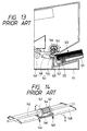
- a sheet feeding apparatus in response to set a sheet-loaded sheet storage device 121 to a body of a laser printer 111, a sheet feeding apparatus, designated at numeral 141, supplies the laser printer 111 with sheets 123 pushed up by a push-up spring 122.
- the sheet feed apparatus 141 comprises a semicylindrical pickup roller 144 coaxially fixed to a drive shaft 142, a stopping roller 147 disposed at both end portions (sides) of the semicylindrical pickup roller 144 and coaxially and rotatably coupled to the drive shaft 142, a retard pad 146 disposed to be elastically brought into contact with the circumference of the semicylindrical pickup roller 144 by means of elastic members (springs) 145, and a sheet guide plate 148 for rotatably supporting the retard pad 146 to guide the sheets 123.
- the sheets 123 fed from the sheet feeding apparatus 141 are supplied through a carrying roller 149 into the body of the laser printer 111.
- Fig. 15 is a cross-sectional illustration of the semicylindrical pickup roller 144 taken along a line X-X in Fig. 14.
- the semicylindrical pickup roller 144 being made of a rubber, is arranged to have a diameter slightly greater than the diameter of the stopping roller 147 and fixedly coupled through a core member 143 to the drive shaft 142.
- the semicylindrical pickup roller 144 has a plurality of grooves 144a formed along its axis and has a notch 144c.
- the sheets 123 placed in the sheet storage device 121 are pushed up by the push-up spring 122 to be pressed against the stopping roller 147 whereby the sheets 123 are positioned for supply.
- the semicylindrical pickup roller 144 is rotated by one revolution in a direction indicated by an arrow in Fig. 13, whereby a leading portion 144b of the semicylindrical pickup roller 144 comes into contact with a front portion of the uppermost (topmost) sheet 123 so that the uppermost sheet 123 is moved forwardly by means of a frictional force relative to the semicylindrical pickup roller 144.
- the retard pad 146 comes into contact with the sheets 123 other than the uppermost sheet 123 to suppress the supply of the sheets 123 by means of a sliding resistance to prevent the following sheets 123 from be supplied simultaneously with the uppermost sheet 123.
- EP-A-345989 describes a sheet feed mechanism for feeding sheets one at a time comprising a hopper loaded with a stack of sheets, a feed roller disposed near the outlet of the hopper and a resilient tongue held in resilient contact with the central section of the feed roller.
- the central section is provided with an alternate circumferencial arrangement of low friction portions and high friction portions. The friction coefficient between the sheet and the low friction portions is smaller than that between the sheet and the tongue, and the friction coefficient between the sheet and the high friction portions is greater than that between the sheet and the tongue.
- JP-A-31 58 329 there is shown a medium issuing device comprising a pick up roller having a low friction portion and a high friction portion, the pick up roller being switchable between a low friction setting and a high friction setting, the low friction setting being effective when a medium is returned to a former position in order to prevent peeling-off of the medium's surface printing during the return operation which would occur if the surface of the medium was in contact with the high friction portion of the pick up roller.
- Patent abstracts of Japan, Vol.13, No. 133, 04th April 1989 shows a paper sheet feed-out device in which a notch is formed at the border portion positioned in the roll turning direction between the surfaces of both a high friction part of a roll and a smooth aluminium surface member.
- JP-A-58 089 5311 there is shown a paper sheet drawing out device in which, in opposition to a drawing out opening face, a semilunar roller is provided along with a belt conveyor, while said semilunar roller is equipped with a low friction member and a high friction member on its periphery and also a conveyance roller.
- a semilunar roller When the semilunar roller is rotated, one paper sheet is taken out in the high friction part due to high frictional contact between said part and said sheet, and drawn out by means of a flat belt at a position where the conveyance roller is opposed to a corresponding roller after one rotation.
- FIG. 1 is a perspective view showing an arrangement of the sheet feeding apparatus according to the first embodiment of this invention. As illustrated in Fig.
- the sheet feeding apparatus designated at numeral 32, comprises a sheet pickup roller 4 fixedly secured to a drive shaft 12, a projection 21 attached to a leading portion 4b of the sheet pickup roller 4 in its rotational direction, a stopping roller 7 disposed at both ends of the sheet pickup roller 4 and coaxially and rotatably couped to the drive shaft 12, a retard pad 6 disposed to be elastically brought into contact with the circumference of the sheet pickup roller 4 by means of elastic members 5, and a sheet guide plate 13 for rotatably supporting the retard pad 6 to guide sheets to be fed to equipment.
- Fig. 2 is an enlarged view showing the sheet pickup roller 4. As illustrated in Fig.
- the sheet pickup roller 4 has a notch portion to substantially form a semicylindrical configuration and is composed of an outer portion and an inner portion which are integrally and fixedly coupled to each other.
- the outer portion of the sheet pickup roller 4 is made of a rubber or the like, and the inner portion thereof acts as a core member 14 of the sheet pickup roller 4 having a center through-hole into which the drive shaft 12 is inserted to be fixedly secured thereto so that the sheet pickup roller 4 is coaxially coupled to the drive shaft 12 to be rotatable in accordance with rotation of the drive shaft 12.
- the core member 14 has a plurality of caves extending along the axis of the center through-hole.
- the projection 21 is equipped with claw portions 22 at its both ends.
- the claw portions 22 are engaged with one cave 14b of the core member 14 from both the sides so that the projection 21 is detachably attached to a predetermined portion of the sheet pickup roller 4.
- the sheet pickup roller 4 has a diameter slightly greater than the diameter of the stopping roller 7 and further has in its circumference (outer portion) a plurality of grooves 4a extending along its own axis.
- the projection 21 is positioned at a portion of the notch portion (designated at 4c) of the sheet pickup roller 4, i.e., positioned at the vicinity of a portion 4b of the sheet pickup roller 4 which acts as a leading portion when the sheet pickup roller 4 rotates in a predetermined direction.
- the projection 21 is made of a material such as polyacetal resin and alkyl benzene sulfonic acid type resin having a coefficient of friction smaller than that of the material of the sheet pickup roller 4. That is, the projection 21 has a smooth surface.
- a tip portion 21a of the projection 21 is arranged to have a thickness whereby the projection 21 attached to the sheet pickup roller 4 slightly protrudes outwardly from the outer circumference of the stopping roller 7 or the outer surface of the projection 21 becomes substantially equal in height to the circumferential surface of the stopping roller 7.
- the protruding amount (t1 in Fig. 3) from the outer circumference of the stopping roller 7 is arranged to be 1 to 3 times the thickness of each sheet (3) to be fed.
- a rear end portion 21b of the projection 21 is arranged to be lowered with respect to the outer circumferential surface of the sheet pickup roller 4 or arranged to be substantially equal in height to the outer circumferential surface of the sheet pickup roller 4.
- the range (arc-length) of the protruding portion 21a of the projection 21 is set to be substantially equal to a range from the contact point between the projection 21 and the retard pad 6 to the leading portion 4b of the sheet pickup roller 4 in the state that the leading portion 4b of the sheet pickup roller 4 comes into contact with the sheet (3) to be fed.
- Fig. 4 is an illustration for describing the sheet supply passage of a laser printer when using the sheet feeding apparatus 32 according to this embodiment.
- sheets 3 are stored in a sheet storage device 31 which is in turn loaded to the body 11 of the laser printer.
- the front (tip) portion of the sheet storage device 31 is coupled to the sheet feeding apparatus 32.
- a resist roller 42 for temporarily stopping the sheet 3.
- the sheet 3 After passing through the resist roller 42, the sheet 3 enters into a carrying passage 43 where there are disposed a charger 35 for charging a recording device (photosensitive drum) 34, an exposure device 36 for converting recording information into optical information so that the recording device 34 is illuminated with the optical information to form an electrostatic latent image on the recording device 34, a developing device for giving a developer with respect to the electrostatic latent image on the recording device 34, a transfer device 38 for transferring the developer on the recording device 34 to the sheet 3, and a fixing device 39 for heating and fixing the developer on the sheet 3.
- a charger 35 for charging a recording device (photosensitive drum) 34
- an exposure device 36 for converting recording information into optical information so that the recording device 34 is illuminated with the optical information to form an electrostatic latent image on the recording device 34
- a developing device for giving a developer with respect to the electrostatic latent image on the recording device 34
- a transfer device 38 for transferring the developer on the recording device 34 to the sheet 3
- a fixing device 39 for
- a cleaning device 33 for removing the remaining developer from the recording device 34
- a sheet-discharging device 44 for guiding the sheet 3 on to an upper cover of the body 11 of the laser printer.
- Fig. 5 shows a drive system for the supply of the sheets 3 into the laser printer body 11.
- a main motor 51 acts as a drive source to drive, through a first gear train 52, the recording device 34 (not shown), the developing device 37, the cleaning device 33, a second gear train 53, and a third gear train 54.
- the second gear train 53 operates, through a first solenoid type clutch 55, the resist roller 42 and further operates, through a second solenoid type clutch 56, the sheet feeding apparatus 32.
- the third gear train 54 operates the fixing device 39 and the sheet-discharging device 44.
- a scanner motor (not shown) of the exposure device 36 starts to rotates.
- the main motor 51 starts to rotates to drive the recording device 34, the developing device 37, the fixing device 39, the cleaning device 33 and the sheet-discharging device 44 which are coupled to the first and third gear trains 52 and 54, thereafter starting the output control of a semiconductor laser (not shown) of the exposure device 36 and the charging control of the charger 35.
- the sheet pickup roller 4 of the sheet feeding apparatus 32 rotates by one revolution whereby one sheet 3 in the sheet storage device 31 is supplied into the carrying passage 41 of the laser printer.
- the sheet 3 supplied takes a waiting state for printing by means of the resist roller 42.
- the exposure device 36 starts to write the image information in the recording device 34 and the recording device 34 rotates for completely writing the image information.
- the image information written therein is developed by the developing device 37.
- the first solenoid type clutch 55 is operated at the timing that the front end portion of the sheet 3 supplied from the resist roller 42 is coincident with the transferring device 38, thereby starting the operation of the resist roller 42.
- the image information on the recording device 34 is transferred onto the sheet 3 in the transferring device 38.
- the aforementioned operation is repeatedly effected with respect to the following sheets 3.
- the sheet 3 on which the image information is transferred is supplied through the carrying passage 43 up to the fixing device 39.
- the fixing device 39 the developer transferred on the sheet 3 is heated by a heating roller (not shown) to be fixed thereon.
- Fig. 6 is a cross-sectional view showing a principal portion of the sheet feeding apparatus 32 which takes the waiting state.
- the sheets 3 stored in the sheet storage device 31 is urged by means of a push-up spring 9 to be pressed against the stopping roller 7 and positioned thereby.
- the projection 21 does not yet come into contact with the sheets 3.
- the sheet pickup roller 4 starts to rotate in a direction indicated by an arrow.
- Fig. 7 is a cross-sectional view showing the principal portion of the sheet feeding apparatus 32 which takes a state immediately after the start of the sheet supply. In Fig.
- Fig. 8 is a cross-sectional view showing the principal portion of the sheet feeding apparatus 32 which takes a sheet-feeding state.
- the front portion of the uppermost sheet 3 is brought into contact with the circumferential surface of the sheet pickup roller 4 to be sent out through a frictional force relative thereto, and is surely brought into contact with the retard pad 6 under a pressure due to the projection 21.
- the retard pad 6 can surely control the second or other sheet so as to prevent the simultaneous supply of the multiple sheets 3.
- the sheet 3 sent out from the sheet feeding apparatus 32 is supplied through carrying rollers (8 in Fig. 6) into the laser printer and then carried and precessed as described above.
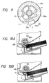
- Fig. 9 is a cross-sectional view taken along the line A-A in Fig. 1 where parts corresponding to those in Fig. 3 are marked with the same numerals and the description thereof will be omitted for brevity.
- a sheet pickup roller 204 made of a rubber or the like, has a diameter slightly greater than that of a stopping roller 7, and has a number of grooves 204a extending along its own axis on its circumference and has a notch portion 204c at a portion of the circumference.
- the sheet pickup roller 204 has a projection 204d at its leading portion 204b which first faces sheets when rotating in a predetermined direction for the pick-up of the sheets.
- This projection 204d may be made of the same material (rubber) as the sheet pickup roller 204 body (outer portion of the sheet pickup roller 204) and may be integrally constructed together with the sheet pickup roller 204 body.
- the projection 204d has a circumferential surface (arc-shaped surface) substantially extending along the circumference of the sheet pickup roller 204 or the circumference of the stopping roller 7. Onto the circumferential surface of the projection 204d there is adhered a film 205 made of a material such as a resin which has a coefficient of friction smaller than that of the sheet pickup roller 204 body.
- the film 205 is made of tetrafluoroethylene polymer.
- the circumferential surface of the film 205 is arranged to have a diameter whereby the film 205 is positioned to be slightly lowered with respect to the circumference of the stopping roller 7 or substantially become equal in height to the circumference of the stopping roller 7.
- the lowered amount (t2 in Fig. 9) of the film 205 is set to be 1 to 3 times the thickness of the sheet (3).
- the projection 204d will be effectively used when its length is set to be equal to a range from the contact point between the projection 204d (film 205) and a retard pad 6 to the leading portion 204b of the sheet pickup roller 204 in the state that the leading portion 204b of the sheet pickup roller 204 comes into contact with the sheet (3) to be fed.
- the sheet pickup roller 204 is made of a rubber whose elasticity is slight so that the sheet pickup roller 204 is scarcely dented, it is appropriate that the projection 204d is arranged to be similar in shape and structure to the projection 21 in Fig. 3.
- Fig. 10A is a cross-sectional view showing the principal portion of the sheet feeding apparatus which takes a state immediately after the start of the sheet-feeding operation.
- the projection 204d first presses the front portion of the uppermost sheet 3 from the upper side and slightly sends out the uppermost sheet 3.
- the film 205 having a coefficient of friction smaller than that of the sheet pickup roller 204 is adhered through an adhesive onto the circumferential surface of the projection 204d, the sheet 3 is not completely sent out therefrom.
- Fig. 10B is a cross-sectional view showing the principal portion of the sheet feeding apparatus which takes a sheet-feeding state.
- the front portion of the uppermost sheet 3 is sent out through a frictional force relative to the circumferential surface of the sheet pickup roller 204 and surely pressed against the retard pad 6 by means of the projection 204d.
- the sheet 3 fed from the sheet feeding apparatus is supplied through carrying rollers (8) into the laser printer and printing-processed as described above.
- Fig. 11 is a cross-sectional view taken along the line A-A in Fig. 1, showing a sheet pickup roller of a sheet feeding apparatus according to this embodiment where parts corresponding to those in Fig. 3 are marked with the same numerals and the description thereof will be omitted for brevity.
- a sheet pickup roller 304 whose outer portion is made of a rubber or the like has a diameter slightly greater than that of a stopping roller 7 and has a number of grooves 304a extending along its own axis.
- the sheet pickup roller 304 has a notch portion 304c and a projection 304d at a leading portion 304 which first faces sheets when rotating in a predetermined direction for the pick-up of the sheets.
- the projection 304d and the sheet pickup roller 304 may be made of the same material and integrally constructed with each other.
- the projection 304d has a circumferential surface (arc-shaped surface) substantially extending along the circumference of the sheet pickup roller 304 or the circumference of the stopping roller 7.
- the circumferential surface of the projection 304d is arranged to have a diameter smaller than that of the stopping roller 7.
- the lowered amount (t3 in Fig. 11) of the projection 304d is set to be approximately 5 times the thickness of the sheet (3).
- the projection 304d will be effectively used when its length is set to be equal to a range from the contact point between the projection 304d and a retard pad 6 to the leading portion 304b of the sheet pickup roller 304 in the state that the leading portion 304b of the sheet pickup roller 304 comes into contact with the sheet (3) to be fed.
- Fig. 12A is a cross-sectional view showing the principal portion of the sheet feeding apparatus which takes a state immediately after the start of the sheet-feeding operation.
- the projection 304d first presses the front portion of the uppermost sheet 3 from the upper side and slightly sends out the uppermost sheet 3.
- the outer surface of the projection 304d is arranged to be lower in height than the circumferential surface of the stopping roller 7, it is possible to prevent the front portion of the sheet 3 from floating, before guiding it to the sliding surface of the retard pad 6.
- FIG. 12B is a cross-sectional view showing the principal portion of the sheet feeding apparatus which takes a sheet-feeding state.
- the front portion of the uppermost sheet 3 is sent out through a frictional force relative to the circumferential surface of the sheet pickup roller 304 and surely pressed against the retard pad 6 by means of the projection 304d.
- the sheet 3 fed from the sheet feeding apparatus is supplied through carrying rollers (8) into the laser printer and printing-processed as described above.
Landscapes
- Engineering & Computer Science (AREA)
- Mechanical Engineering (AREA)
- Sheets, Magazines, And Separation Thereof (AREA)
Claims (7)
- Appareil d'alimentation de feuilles destiné à alimenter des feuilles (3) de façon intermittente, comprenant:- des moyens formant rouleaux (4 ; 204 ; 304, 7) qui incluent un rouleau de saisie de feuilles (4 ; 204 ; 304) fixé a un arbre d'entraînement rotatif (12), et des moyens formant rouleaux cylindriques (7) accouplés en rotation audit arbre d'entraînement rotatif (12) et disposés sur les deux côtés dudit rouleau de saisie de feuilles (4 ; 204 ; 304), et- un coussinet (6) sollicité par des moyens élastiques (5) pour être pressé contre lesdits moyens formant rouleaux (4 ; 204 ; 304, 7),
caractérisé en ce que :- ledit rouleau de saisie de feuilles (4 ; 204 ; 304) a une section transversale qui comprend une partie d'arc et une partie de corde de façon à former sensiblement une configuration semi-cylindrique, et- une projection (21 ; 204d ; 304d) prévue à ladite partie de corde dudit rouleau de saisie de feuilles (4 ; 204 ; 304), ladite projection (21 ; 204d ; 304d) étant prévue à un emplacement de façon à venir en contact avec les feuilles (3), dans la direction d'alimentation, avant une partie d'attaque (4b ; 204b ; 304b) agencée a une partie d'extrémité de ladite partie d'arc dudit rouleau de saisie de feuilles (4 ; 204 ; 304). - Appareil d'alimentation de feuilles selon la revendication 1, caractérisé en ce qu'une surface extérieure de ladite projection (21 ; 204d ; 304d) se projette légèrement vers l'extérieur, ou bien qu'elle s'abaisse vers l'intérieur depuis une surface extérieure desdits moyens formant rouleaux cylindriques (7).
- Appareil d'alimentation de feuilles selon la revendication 1, caractérisé en ce qu'une surface extérieure de ladite projection (21 ; 204b ; 304d) est égale, quant à sa hauteur en section transversale depuis un axe central dudit arbre d'entraînement (12), à une surface extérieure desdits moyens formant rouleaux cylindriques (7).
- Appareil d'alimentation de feuilles selon l'une des revendications 1, 2 ou 3, caractérisé en ce qu'un film (205) est adhéré sur ladite surface extérieure de ladite projection (204b), ledit film (205) ayant un coefficient de friction inférieur à un coefficient de friction dudit rouleau de saisie de feuilles (204).
- Appareil d'alimentation de feuilles selon la revendication 4, caractérisé en ce que ledit film (205) est réalisé en polymère de tétrafluoroéthylène.
- Appareil d'alimentation de feuilles selon l'une des revendications 1, 2 ou 3, caractérisé en ce que ladite projection (21 ; 304d) est réalisée en un matériau ayant un coefficient de friction inférieur à un coefficient de friction dudit rouleau de saisie de feuilles (4 ; 304).
- Appareil d'alimentation de feuilles selon la revendication 6, caractérisé en ce que ladite projection (21 ; 304d) est réalisée en un matériau choisi parmi une résine poly-acétal et une résine de type alkyle-benzène-acide-sulfonique.
Applications Claiming Priority (2)
| Application Number | Priority Date | Filing Date | Title |
|---|---|---|---|
| JP52558/92 | 1992-03-11 | ||
| JP4052558A JP2512258B2 (ja) | 1992-03-11 | 1992-03-11 | シ―ト給送装置 |
Publications (2)
| Publication Number | Publication Date |
|---|---|
| EP0560254A1 EP0560254A1 (fr) | 1993-09-15 |
| EP0560254B1 true EP0560254B1 (fr) | 1997-06-11 |
Family
ID=12918149
Family Applications (1)
| Application Number | Title | Priority Date | Filing Date |
|---|---|---|---|
| EP93103682A Expired - Lifetime EP0560254B1 (fr) | 1992-03-11 | 1993-03-08 | Appareil d'alimentation de feuilles |
Country Status (4)
| Country | Link |
|---|---|
| US (1) | US5372359A (fr) |
| EP (1) | EP0560254B1 (fr) |
| JP (1) | JP2512258B2 (fr) |
| DE (1) | DE69311406T2 (fr) |
Families Citing this family (41)
| Publication number | Priority date | Publication date | Assignee | Title |
|---|---|---|---|---|
| JP3119754B2 (ja) * | 1992-12-24 | 2000-12-25 | キヤノン株式会社 | 記録装置 |
| JPH07172598A (ja) * | 1993-12-22 | 1995-07-11 | Minolta Co Ltd | 給紙装置 |
| EP0686590B1 (fr) * | 1993-12-27 | 1999-07-14 | Pfu Limited | Dispositif d'avance automatique du papier et cadre pour un dispositif d'introduction de documents |
| JP3448097B2 (ja) * | 1994-05-19 | 2003-09-16 | ブラザー工業株式会社 | 給紙装置 |
| US5537227A (en) * | 1994-10-14 | 1996-07-16 | Hewlett-Packard Company | Paper picking and separator system for facsmile or copy machine |
| US5570876A (en) * | 1994-10-14 | 1996-11-05 | Hewlett-Packard Company | Asymmetrical paper separator roller for facsimile or copy machine |
| US5918873A (en) * | 1995-03-30 | 1999-07-06 | Canon Kabushiki Kaisha | Sheet supplying apparatus which regulates tip end of sheet by first and second abutment means |
| CH690853A5 (fr) * | 1995-07-10 | 2001-02-15 | Olivetti Lexikon Spa | Dispositif d'introduction de matériaux plats. |
| US5863036A (en) * | 1995-10-20 | 1999-01-26 | Ricoh Company, Ltd. | Sheet feeding device and image forming apparatus having the same |
| US5630583A (en) * | 1995-12-22 | 1997-05-20 | Hewlett-Packard Company | Sheet media feeding mechanism having a variable radius feed roller |
| DE69608534T2 (de) * | 1995-12-26 | 2000-09-14 | Brother Kogyo K.K., Nagoya | Bogenzuführvorrichtung mit verbesserter Trennung der Bogen in Unabhängigkeit der Steifigkeit und Grösse der Bogen |
| JP3521102B2 (ja) * | 1996-02-27 | 2004-04-19 | 株式会社リコー | 給紙装置 |
| JP3320982B2 (ja) * | 1996-07-09 | 2002-09-03 | 京セラミタ株式会社 | 給紙装置 |
| US5882004A (en) * | 1996-09-18 | 1999-03-16 | Hewlett-Packard Co. | Automatic sheet feeding mechanism |
| JPH10101241A (ja) * | 1996-09-30 | 1998-04-21 | Oki Data:Kk | 給紙装置 |
| DE69719282T2 (de) * | 1996-10-22 | 2003-11-13 | Seiko Epson Corp., Tokio/Tokyo | Blattzuführvorrichtung |
| US5996989A (en) * | 1997-05-02 | 1999-12-07 | Lexmark International, Inc. | Sheet separator friction pad |
| JP3702600B2 (ja) * | 1997-08-25 | 2005-10-05 | ブラザー工業株式会社 | シート搬送装置 |
| JP2000044072A (ja) * | 1998-07-30 | 2000-02-15 | Brother Ind Ltd | 給紙装置 |
| US6135444A (en) * | 1998-12-15 | 2000-10-24 | Hewlett-Packard Company | Automatic sheet feeding mechanism |
| JP2001026327A (ja) * | 1999-07-16 | 2001-01-30 | Ricoh Co Ltd | 給紙装置 |
| CN1200863C (zh) * | 2000-04-06 | 2005-05-11 | 株式会社理光 | 送纸装置及图像形成装置 |
| JP3680312B2 (ja) * | 2000-05-31 | 2005-08-10 | セイコーエプソン株式会社 | 給紙装置 |
| JP3611781B2 (ja) * | 2000-08-29 | 2005-01-19 | シャープ株式会社 | 画像形成装置の給紙装置 |
| GB0102342D0 (en) * | 2001-01-30 | 2001-03-14 | Smithkline Beecham Plc | Pharmaceutical formulation |
| US6932529B2 (en) * | 2002-08-13 | 2005-08-23 | Hewlett-Packard Development Company, L.P. | Method and systems for accessing a separation pad in a printing device |
| CN1839081B (zh) * | 2003-03-10 | 2010-09-15 | 迪布尔特有限公司 | 现金分发自动银行机及方法 |
| JP4006366B2 (ja) * | 2003-07-02 | 2007-11-14 | キヤノン株式会社 | シート給送装置及び画像形成装置 |
| US7172091B2 (en) * | 2004-05-07 | 2007-02-06 | Sweports Limited | Mop dispenser |
| US7614622B2 (en) * | 2004-07-27 | 2009-11-10 | Canon Kabushiki Kaisha | Sheet feeding apparatus and image forming apparatus |
| DE102005032601A1 (de) * | 2005-01-07 | 2006-07-20 | Heidelberger Druckmaschinen Ag | Druckmaschine |
| KR100692573B1 (ko) * | 2005-08-31 | 2007-03-13 | 삼성전자주식회사 | 화상형성기기의 급지장치 |
| DE202006002248U1 (de) | 2006-02-10 | 2006-08-03 | Bdt Ag | Zuführrolle, Zuführrollenbaugruppe und Substrathandhabungssystem |
| CN101868300B (zh) * | 2007-11-12 | 2013-07-24 | 国际皇冠电子株式会社 | 用于碎纸机的给纸辊 |
| BR112014000728A2 (pt) * | 2011-07-13 | 2017-02-14 | Sca Hygiene Prod Ab | dispositivo distribuidor e pilha de produtos em folha |
| JP5389129B2 (ja) * | 2011-09-14 | 2014-01-15 | 住友ゴム工業株式会社 | 給紙ローラ |
| CN104736029A (zh) | 2012-10-26 | 2015-06-24 | Sca卫生用品公司 | 分配器 |
| US10390664B2 (en) | 2012-10-26 | 2019-08-27 | Essity Hygiene And Health Aktiebolag | Separation unit and a dispenser comprising a separation unit |
| ES2986780T3 (es) * | 2012-10-26 | 2024-11-12 | Essity Hygiene & Health Ab | Unidad de separación y dispensador que comprende una unidad de separación |
| WO2015167371A1 (fr) | 2014-04-28 | 2015-11-05 | Sca Hygiene Products Ab | Distributeur |
| KR101761657B1 (ko) * | 2015-08-10 | 2017-07-26 | 노틸러스효성 주식회사 | 선단 정렬부재를 구비한 픽업롤러 및 이를 이용한 매체분리장치 |
Family Cites Families (19)
| Publication number | Priority date | Publication date | Assignee | Title |
|---|---|---|---|---|
| DE1067451B (de) * | 1959-10-22 | Patt scheid Karlheinz Kaiser (Bez Dusseldorf) | Selbsttätige Zufuhrvorrichtung fur Briefe, Karten, Formulare oder Bogen von einem Stapel fur Druck und andere Verarbeitungsmaschmen | |
| US1956229A (en) * | 1932-03-16 | 1934-04-24 | Specialty Automatic Machine Co | Sheet-feeding mechanism |
| US2269571A (en) * | 1941-08-16 | 1942-01-13 | E G Staude Mfg Company | Sheet feeder and method of using |
| JPS57209140A (en) * | 1981-06-19 | 1982-12-22 | Ricoh Co Ltd | Automatic paper feeder |
| JPS5889531A (ja) * | 1981-11-17 | 1983-05-27 | Omron Tateisi Electronics Co | 紙葉類繰出装置 |
| GB2174370B (en) * | 1985-04-15 | 1989-01-25 | Mita Industrial Co Ltd | A mechanism for preventing the feeding of more than one sheet of paper at one time |
| JPH0647418B2 (ja) * | 1986-07-31 | 1994-06-22 | キヤノン株式会社 | シ−ト給送装置 |
| JPS63300028A (ja) * | 1987-05-28 | 1988-12-07 | Toyo Commun Equip Co Ltd | 紙葉繰り出し装置 |
| JPS6453955A (en) * | 1987-08-25 | 1989-03-01 | Konishiroku Photo Ind | Conveying device for recording sheet of image recording device |
| JPH01294133A (ja) * | 1988-05-19 | 1989-11-28 | Canon Inc | シート給送装置 |
| JPH0745476Y2 (ja) * | 1988-06-08 | 1995-10-18 | 沖電気工業株式会社 | 用紙送り機構 |
| JP2603302B2 (ja) * | 1988-06-23 | 1997-04-23 | キヤノン株式会社 | シート給送装置 |
| JPH02127330A (ja) * | 1988-11-04 | 1990-05-16 | Canon Inc | シート給送装置 |
| JPH02132025A (ja) * | 1988-11-11 | 1990-05-21 | Canon Inc | シート給送装置 |
| US5068714A (en) * | 1989-04-05 | 1991-11-26 | Robert Bosch Gmbh | Method of electrically and mechanically connecting a semiconductor to a substrate using an electrically conductive tacky adhesive and the device so made |
| JPH03113336A (ja) * | 1989-09-28 | 1991-05-14 | Yokogawa Electric Corp | 半導体圧力センサー |
| JPH03158329A (ja) * | 1989-11-15 | 1991-07-08 | Hitachi Ltd | 媒体発行装置 |
| JPH03162331A (ja) * | 1989-11-20 | 1991-07-12 | Canon Inc | 給紙装置 |
| JPH03200637A (ja) * | 1989-12-28 | 1991-09-02 | Canon Inc | シート給送装置 |
-
1992
- 1992-03-11 JP JP4052558A patent/JP2512258B2/ja not_active Expired - Fee Related
-
1993
- 1993-03-05 US US08/026,700 patent/US5372359A/en not_active Expired - Fee Related
- 1993-03-08 DE DE69311406T patent/DE69311406T2/de not_active Expired - Fee Related
- 1993-03-08 EP EP93103682A patent/EP0560254B1/fr not_active Expired - Lifetime
Also Published As
| Publication number | Publication date |
|---|---|
| JPH06286893A (ja) | 1994-10-11 |
| US5372359A (en) | 1994-12-13 |
| DE69311406T2 (de) | 1997-10-02 |
| DE69311406D1 (de) | 1997-07-17 |
| EP0560254A1 (fr) | 1993-09-15 |
| JP2512258B2 (ja) | 1996-07-03 |
Similar Documents
| Publication | Publication Date | Title |
|---|---|---|
| US5372359A (en) | Sheet feeding apparatus | |
| EP0504833B1 (fr) | Appareil pour l'alimentation en feuilles | |
| JPH048112Y2 (fr) | ||
| US5244191A (en) | Sheet feeding apparatus for image recording system | |
| JPH03166135A (ja) | 踏子操作のモジュール式巻き上げ給紙装置 | |
| JP2001048357A (ja) | 用紙後端規制部材 | |
| US5765093A (en) | Image recording apparatus with recording medium bending | |
| EP0562320B1 (fr) | Dispositif d'alimentation de feuilles par frottement du bas d'une pile | |
| JPH0628515Y2 (ja) | 給紙装置 | |
| JPH11334922A (ja) | シート給送装置及びこの装置を備えた画像形成装置 | |
| JPH082721A (ja) | 給紙装置 | |
| JPH11322095A (ja) | シート給送装置及び画像形成装置 | |
| JPH05201557A (ja) | 給紙装置 | |
| JP3521039B2 (ja) | 給紙機構 | |
| EP0367201B1 (fr) | Dispositif d'alimentation de feuilles | |
| JP3087569B2 (ja) | 給紙装置 | |
| JP3316398B2 (ja) | シート給送装置 | |
| JP3548316B2 (ja) | 用紙供給装置及び画像形成装置 | |
| JPH038640A (ja) | 自動給紙装置 | |
| JPH052505Y2 (fr) | ||
| JPH032530Y2 (fr) | ||
| JP3338166B2 (ja) | 画像形成装置 | |
| JPH0754184Y2 (ja) | 枚葉紙載置トレイ | |
| JPH0412037Y2 (fr) | ||
| KR0135735Y1 (ko) | 전자사진 프로세서의 화상형성장치 |
Legal Events
| Date | Code | Title | Description |
|---|---|---|---|
| PUAI | Public reference made under article 153(3) epc to a published international application that has entered the european phase |
Free format text: ORIGINAL CODE: 0009012 |
|
| 17P | Request for examination filed |
Effective date: 19930308 |
|
| AK | Designated contracting states |
Kind code of ref document: A1 Designated state(s): DE FR GB |
|
| 17Q | First examination report despatched |
Effective date: 19941115 |
|
| GRAG | Despatch of communication of intention to grant |
Free format text: ORIGINAL CODE: EPIDOS AGRA |
|
| GRAH | Despatch of communication of intention to grant a patent |
Free format text: ORIGINAL CODE: EPIDOS IGRA |
|
| GRAH | Despatch of communication of intention to grant a patent |
Free format text: ORIGINAL CODE: EPIDOS IGRA |
|
| GRAA | (expected) grant |
Free format text: ORIGINAL CODE: 0009210 |
|
| AK | Designated contracting states |
Kind code of ref document: B1 Designated state(s): DE FR GB |
|
| ET | Fr: translation filed | ||
| REF | Corresponds to: |
Ref document number: 69311406 Country of ref document: DE Date of ref document: 19970717 |
|
| PLBE | No opposition filed within time limit |
Free format text: ORIGINAL CODE: 0009261 |
|
| 26N | No opposition filed | ||
| REG | Reference to a national code |
Ref country code: GB Ref legal event code: IF02 |
|
| PGFP | Annual fee paid to national office [announced via postgrant information from national office to epo] |
Ref country code: DE Payment date: 20060302 Year of fee payment: 14 |
|
| PGFP | Annual fee paid to national office [announced via postgrant information from national office to epo] |
Ref country code: GB Payment date: 20060308 Year of fee payment: 14 Ref country code: FR Payment date: 20060308 Year of fee payment: 14 |
|
| GBPC | Gb: european patent ceased through non-payment of renewal fee |
Effective date: 20070308 |
|
| REG | Reference to a national code |
Ref country code: FR Ref legal event code: ST Effective date: 20071130 |
|
| PG25 | Lapsed in a contracting state [announced via postgrant information from national office to epo] |
Ref country code: DE Free format text: LAPSE BECAUSE OF NON-PAYMENT OF DUE FEES Effective date: 20071002 |
|
| PG25 | Lapsed in a contracting state [announced via postgrant information from national office to epo] |
Ref country code: GB Free format text: LAPSE BECAUSE OF NON-PAYMENT OF DUE FEES Effective date: 20070308 |
|
| PG25 | Lapsed in a contracting state [announced via postgrant information from national office to epo] |
Ref country code: FR Free format text: LAPSE BECAUSE OF NON-PAYMENT OF DUE FEES Effective date: 20070402 |