EP0560367A1 - Appareil pour rechercher la piste dans une unité d'enregistrement avec type de tête rotatif - Google Patents
Appareil pour rechercher la piste dans une unité d'enregistrement avec type de tête rotatif Download PDFInfo
- Publication number
- EP0560367A1 EP0560367A1 EP93103964A EP93103964A EP0560367A1 EP 0560367 A1 EP0560367 A1 EP 0560367A1 EP 93103964 A EP93103964 A EP 93103964A EP 93103964 A EP93103964 A EP 93103964A EP 0560367 A1 EP0560367 A1 EP 0560367A1
- Authority
- EP
- European Patent Office
- Prior art keywords
- track
- head
- signal
- pilot signal
- record
- Prior art date
- Legal status (The legal status is an assumption and is not a legal conclusion. Google has not performed a legal analysis and makes no representation as to the accuracy of the status listed.)
- Withdrawn
Links
Images


Classifications
-
- G—PHYSICS
- G11—INFORMATION STORAGE
- G11B—INFORMATION STORAGE BASED ON RELATIVE MOVEMENT BETWEEN RECORD CARRIER AND TRANSDUCER
- G11B15/00—Driving, starting or stopping record carriers of filamentary or web form; Driving both such record carriers and heads; Guiding such record carriers or containers therefor; Control thereof; Control of operating function
- G11B15/18—Driving; Starting; Stopping; Arrangements for control or regulation thereof
- G11B15/46—Controlling, regulating, or indicating speed
- G11B15/467—Controlling, regulating, or indicating speed in arrangements for recording or reproducing wherein both record carriers and heads are driven
- G11B15/4673—Controlling, regulating, or indicating speed in arrangements for recording or reproducing wherein both record carriers and heads are driven by controlling the speed of the tape while the head is rotating
- G11B15/4675—Controlling, regulating, or indicating speed in arrangements for recording or reproducing wherein both record carriers and heads are driven by controlling the speed of the tape while the head is rotating with provision for information tracking
- G11B15/4676—Controlling, regulating, or indicating speed in arrangements for recording or reproducing wherein both record carriers and heads are driven by controlling the speed of the tape while the head is rotating with provision for information tracking using signals recorded in tracks disposed in parallel with the scanning direction
- G11B15/4677—Controlling, regulating, or indicating speed in arrangements for recording or reproducing wherein both record carriers and heads are driven by controlling the speed of the tape while the head is rotating with provision for information tracking using signals recorded in tracks disposed in parallel with the scanning direction using auxiliary signals, i.e. pilot signals
- G11B15/4678—Controlling, regulating, or indicating speed in arrangements for recording or reproducing wherein both record carriers and heads are driven by controlling the speed of the tape while the head is rotating with provision for information tracking using signals recorded in tracks disposed in parallel with the scanning direction using auxiliary signals, i.e. pilot signals superimposed on the main signal track
-
- G—PHYSICS
- G11—INFORMATION STORAGE
- G11B—INFORMATION STORAGE BASED ON RELATIVE MOVEMENT BETWEEN RECORD CARRIER AND TRANSDUCER
- G11B5/00—Recording by magnetisation or demagnetisation of a record carrier; Reproducing by magnetic means; Record carriers therefor
- G11B5/008—Recording on, or reproducing or erasing from, magnetic tapes, sheets, e.g. cards, or wires
- G11B5/00813—Recording on, or reproducing or erasing from, magnetic tapes, sheets, e.g. cards, or wires magnetic tapes
- G11B5/00878—Recording on, or reproducing or erasing from, magnetic tapes, sheets, e.g. cards, or wires magnetic tapes transducing different track configurations or formats on the same tape
-
- G—PHYSICS
- G11—INFORMATION STORAGE
- G11B—INFORMATION STORAGE BASED ON RELATIVE MOVEMENT BETWEEN RECORD CARRIER AND TRANSDUCER
- G11B5/00—Recording by magnetisation or demagnetisation of a record carrier; Reproducing by magnetic means; Record carriers therefor
- G11B5/48—Disposition or mounting of heads or head supports relative to record carriers ; arrangements of heads, e.g. for scanning the record carrier to increase the relative speed
- G11B5/58—Disposition or mounting of heads or head supports relative to record carriers ; arrangements of heads, e.g. for scanning the record carrier to increase the relative speed with provision for moving the head for the purpose of maintaining alignment of the head relative to the record carrier during transducing operation, e.g. to compensate for surface irregularities of the latter or for track following
- G11B5/584—Disposition or mounting of heads or head supports relative to record carriers ; arrangements of heads, e.g. for scanning the record carrier to increase the relative speed with provision for moving the head for the purpose of maintaining alignment of the head relative to the record carrier during transducing operation, e.g. to compensate for surface irregularities of the latter or for track following for track following on tapes
- G11B5/588—Disposition or mounting of heads or head supports relative to record carriers ; arrangements of heads, e.g. for scanning the record carrier to increase the relative speed with provision for moving the head for the purpose of maintaining alignment of the head relative to the record carrier during transducing operation, e.g. to compensate for surface irregularities of the latter or for track following for track following on tapes by controlling the position of the rotating heads
- G11B5/592—Disposition or mounting of heads or head supports relative to record carriers ; arrangements of heads, e.g. for scanning the record carrier to increase the relative speed with provision for moving the head for the purpose of maintaining alignment of the head relative to the record carrier during transducing operation, e.g. to compensate for surface irregularities of the latter or for track following for track following on tapes by controlling the position of the rotating heads using bimorph elements supporting the heads
- G11B5/5921—Disposition or mounting of heads or head supports relative to record carriers ; arrangements of heads, e.g. for scanning the record carrier to increase the relative speed with provision for moving the head for the purpose of maintaining alignment of the head relative to the record carrier during transducing operation, e.g. to compensate for surface irregularities of the latter or for track following for track following on tapes by controlling the position of the rotating heads using bimorph elements supporting the heads using auxiliary signals, e.g. pilot signals
- G11B5/5922—Disposition or mounting of heads or head supports relative to record carriers ; arrangements of heads, e.g. for scanning the record carrier to increase the relative speed with provision for moving the head for the purpose of maintaining alignment of the head relative to the record carrier during transducing operation, e.g. to compensate for surface irregularities of the latter or for track following for track following on tapes by controlling the position of the rotating heads using bimorph elements supporting the heads using auxiliary signals, e.g. pilot signals superimposed on the main signal
Definitions
- the present invention relates to a tracking control apparatus of rotary head type recording unit using pilot signals for detecting a tracking error.
- a VTR with a pair of rotary heads for slantly forming tracks on a magnetic tape wound around a tape guide drum is known.
- a digital VTR which records a digital video signal, a digital audio signal, and a control/display digital sub data on tracks on a time division basis has been proposed.
- a tracking control apparatus which records a tacking control pilot signal in each region disposed at both the ends of a track (these regions are referred to as ATF areas) is also known.
- Fig. 16 is a schematic diagram showing a conventional recording system for recording an ATF pilot signal on each track.
- x represents the scanning direction of a pair of rotary heads
- y represents the traveling direction of a magnetic tape
- a and B represent tracks formed by the rotary heads
- Dx represents the offset distance between the ends of a track A and a track B just adjacent thereto
- a hatched region represents a record area of a pilot signal.
- the extended direction of a gap formed on one pair of the heads differs from that on the other pair so as to provide an azimuth loss which reduces a crosstalk between two tracks.
- slant tracks are horizontally depicted.
- the length of the record region of a pilot signal is defined as multiples of the offset distance Dx.
- the offset distance Dx is mechanically defined by a mechanism including a rotating drum and a tape traveling mechanism of a VTR.
- the pilot signal has only one frequency. In this reference, the frequency f is set to approximately 1 MHz.
- the pilot signal is recorded in the first DX region and the fourth DX region.
- the pilot signal is recorded in the third DX region.
- the pilot signal is repeatedly recorded in such a sequence.
- the length necessary for controlling a tracking operation is 5 Dx. This length is referred to as an ATF area.
- Fig. 16 shows a record pattern of the pilot signal on the side where the rotary heads enters (namely, the head entering side). However, the record pattern on the head leaving side is the same as that on the head entering side.
- a tracking error is detected as follows.
- one head with the same azimuth angle as a track A scans this track, it reproduces a pilot signal from this track, a crosstalk of a pilot signal from one of adjacent two tracks, and then a crosstalk of a pilot signal from the other.
- the other head with the same azimuth as a track B scans this track, it reproduces a pilot signal from this track, a cross talk of a pilot signal from one of adjacent two tracks, and then a crosstalk of a pilot signal from the other.
- the first reproduction output of the pilot signal on the same azimuth track is relatively large.
- This reproduction output is used as a timing reference.
- the levels of the crosstalks of both the two adjacent tracks are sampled and held.
- the length of the record region of a pilot signal can be doubled (namely, 2 Dx) as shown in Fig. 17.
- the length of the ATF area accordingly becomes long.
- the length of the ATF area should be as short as possible.
- an object of the present invention s to provide a tracking control apparatus with long record regions for pilot signals so as to stably perform a tracking control operation without a tradeoff of a decrease of data record regions.
- Another object of the present invention is to provide a tracking control apparatus for quickly performing a tracking control operation in such situations as just after the capstan motor starts rotating and when a large external disturbance occurs.
- a tracking control apparatus of rotary head type recording unit having a first rotary head and a second rotary head for slantly forming on a magnetic tape a pair of a first track and a second track respectively, the first track and the second track having a head entering side tracking region and a head leaving side tracking region, the head entering side tracking region being disposed in the vicinity of a head entering side of the first and second tracks, the head leaving side tracking region being disposed in the vicinity of a head leaving side of the first and second tracks, the apparatus comprising: circuit for generating a first pilot signal and a second pilot signal used for controlling a tracking operation, the frequency of the first pilot signal being different from that of the second pilot signal; and circuit for forming record signals to be supplied to the rotary heads in such a way that in the head entering side tracking region the first pilot signal is recorded at a predetermined position on the first track and the second pilot signal is recorded at a predetermined position preceded by the first pilot signal recording region on the second track just
- the apparatus according to the first aspect, wherein the first pilot signal is recorded, followed by the second pilot signal.
- a first pilot signal for generating a timing reference and a second pilot signal for detecting a tracking error are recorded on a first track and a second track just adjacent thereto.
- the ATF area is not widened.
- two adjacent tracks on which the first and second pilot signals are recorded on the head entering side are reverse of those on the head leaving side, even if a head clog takes place, the tracking control operation can be performed.
- This embodiment is a digital VTR which records a digital video signal, a digital audio signal, and a control sub data on a magnetic tape in a predetermined track format.
- a digital video signal for one frame is recorded along with a digital audio signal and a sub data on a plurality of tracks (10 tracks in the NTSC system).
- a pair of rotary heads with different azimuth angles are used. Practically, two heads disposed at intervals of 180° on a rotating drum are used. Alternatively, a double azimuth head which has two gaps closely disposed with different azimuth angles is used.
- Fig. 1 is a block diagram showing the construction of a record circuit for recording pilot signals used for a tracking control operation.
- reference numeral 1 is a frequency division circuit.
- the frequency division circuit 1 receives a system clock from an input terminal 2.
- the frequency division circuit 1 generates a first pilot signal with frequency f1 and a second pilot signal with frequency f2.
- the values of these frequencies are only examples. However, the relation of (f1 ⁇ f2) should be satisfied. Preferably, the relation (f1 ⁇ f2) should be satisfied.
- the frequency f1 of the first pilot signal should be so low that a pulse signal as a timing reference can be generated when the pilot signal is reproduced by a head with a different azimuth angle as it was recorded.
- the crosstalk of a pilot signal with frequency f2 is used.
- the crosstalk component of f1 should differ from the crosstalk component of f2 so that they can be separated by a filter.
- the frequency f2 should be so high that the crosstalk component of f2 on a track far spaced can be suppressed by an azimuth loss.
- Two pilot signals of the frequency division circuit 1 are supplied to a multiplexer 3.
- the multiplexer 3 receives from an input terminal 4 data to be placed in a data area of each track.
- the multiplexer 3 is controlled with a control signal received from an input terminal 5 according to a track format where an ATF area is disposed at both the ends of one track (these ends are referred to as the head entering side and the head leaving side).
- a digital video signal, a digital audio signal, and sub data are recorded on a time division basis.
- An output signal of the multiplexer 3 is supplied to a rotary head HB through a record amplifier 6B.
- the output signal is supplied to a rotary head HA through a delay circuit 7 and a record amplifier 6A.
- the rotary heads HA and HB have a double azimuth construction.
- the delay circuit 7 causes the two heads to record respective data at the same time. Thus, with one scanning operation, both the tracks A and B are formed at the same time.
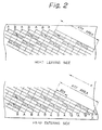
- Fig. 2 is a schematic diagram showing record patterns of pilot signals recorded on the head entering side and the head leaving side of a magnetic tape.
- the pilot signals are recorded at positions which are represented by multiples of the offset distance Dx between just adjacent tracks.
- the length of the ATF area is 7 Dx.
- the example of Fig. 2 shows SP mode where the track pitch Tp is 9 ⁇ m, the offset distance Dx is 4.54 ⁇ m, the length of the ATF area is 22.7 ⁇ m, and the width of each head is 10.5 ⁇ m.
- the pilot signals are recorded in the reverse relation of the head entering side.
- Dx region which is positioned in the second and third from the scanning direction of heads in the ATF area of each track B, a first pilot signal is recorded.
- a second pilot signal is recorded in the fifth and sixth Dx regions in the ATF area of each track A.
- the relative positions between the heads and the magnetic tape can be obtained by magnetically detecting the rotation of the rotating drum.
- the control signal of the multiplexer 3 is formed of this detected result and the clock timing.
- the pilot signals recorded in the above-mentioned manner are reproduced by the rotary heads HA and HB as shown in Fig. 3.
- the reproduction signals are supplied to tracking error detection circuits 12A and 12B through reproduction amplifiers 11A and 11B, respectively.
- the reproduction signals are supplied to a reproduction signal process circuit (not shown in the figure) so as to reproduce a digital video signal, a digital audio signal, and sub data.
- the tracking error detection circuit 12A outputs error signals TE1 and TE2.
- the error signals TE1 and TE2 are sent to A/D converters 13A and 13B, respectively.
- the A/D converters 13A and 13B convert the error signals TE1 and TE2 into digital signals.
- the A/D converters 13A and 13B receive sampling pulses from a monostable multivibrator 14 and a pulse generation circuit 15.
- the monostable multivibrator 14 receives a rotating drum detection signal from an input terminal 16.
- the resultant tracking error signals TE1 and TE2 are supplied to a tracking servo circuit 17.
- the tracking servo circuit 17 is constructed of a microcomputer.
- the tracking servo circuit 17 forms a tracking control signal.
- the tracking control signal is supplied to a servo circuit of a capstan motor.
- the servo circuit controls the tape speed so that the reproduction signals can be correctly tracked.
- a tracking control means in addition to a means for controlling the tape speed, a means for displacing the height of the tape heads by using piezo-electric elements can be used.
- the tracking error detection circuit 12A has a construction shown in Fig. 4. Reproduction signals are supplied from an input terminal 21 to a low-pass filter 22.
- the low-pass filter 22 passes pilot signals with frequencies f1 and f2.
- the low-pass filter 22 is connected to a pulse detection circuit 23 and a band-pass filter 24.
- the band-pass filter 24 passes the component of frequency f2.
- the pulse detection circuit 23 forms a pulse signal P0 according to the pilot signal with frequency f1.
- This pulse signal P0 is supplied to a sampling pulse generation circuit 25.
- the sampling pulse generation circuit 25 outputs sampling pulses P1 and P2.
- the sampling pulses P1 and P2 are supplied to sample/hold circuits 27 and 28, respectively.
- the sample/hold circuits 27 and 28 receives the output signal of the band-pass filter 24 through an envelop detection circuit 26.
- the sample/hold circuits 27 and 28 output signals E1 and E2, respectively.
- the output signals E1 and E2 are supplied to a subtraction circuit 29.
- the subtraction circuit 29 outputs a tracking error signal of (E1 - E2) from an output terminal 30.
- the tracking error detection circuit 12B has the same construction as the tracking error detection circuit 12A shown in Fig. 4. Next, with reference to Fig. 5, a tracking error detection process will be described.
- Fig. 5A shows a part of the record pattern on the head entering side shown in Fig. 2. In Fig. 5, for simplicity, it is assumed that the width of the heads is equal to the track pitch and the deviation of the waveform of the reproduction output is ignored.
- the reproduction signal contains a same azimuth reproduction output of a pilot signal (f1) with a large level, a crosstalk of a pilot signal (f2) of an adjacent track (namely, an upper track B1 in Fig. 5A), and a crosstalk of a pilot signal (f2) of another adjacent track (namely, a lower track B2 in Fig. 5A).
- the envelop of the crosstalk component is proportional to the amount of deviation of the head HA to the center of the track A.
- the pulse detection circuit 23 of the tracking error detection circuit 12A generates a pulse signal P0 according to the pilot signal with frequency f1 of the reproduction signal as shown in Fig. 5B. According to for example a trailing edge of the pulse signal P0, sampling pulses P1 and P2 are generated.
- the sample/hold circuits 27 and 28 sample the envelop of the crosstalk of the pilot signal with frequency f2 by using the sampling pulses P1 and P2.
- the subtraction output of the signals E1 and E2 (namely, the tracking error signal TE1) is formed.
- the level and polarity of the tracking error signal TE1 represent the amount of deviation of the head HA to the center of the relevant track and the direction thereof. When there is no track deviation, the level of the signal TE1 is zero. When the head HA upwardly deviates in Fig. 5A, the polarity of the signal TE1 is plus (+) and the level thereof accords with the amount of deviation (error). When the head HA downwardly deviates in Fig. 5A, the polarity of the signal TE1 is minus (-) and the level thereof accords with the amount of deviation (error).
- the tracking error detection circuit 12B detects a tracking error.
- the rotary head HB scans a track B, it can detect a tracking error in the same manner as described above.
- a tracking error signal TE2 is generated.
- the tracking servo circuit 17 calculates the average value of the tracking error signals TE1 and TE2 and accordingly controls the tape speed.
- the corresponding tracking error signal becomes zero. In this situation, the head clog is detected by another means. Only a tracking error signal according to the non-clogged head is treated as a valid signal.
- the frequency f1 of a first pilot signal is low, even if the azimuth of a head is different from a track that the head scans, a relatively large reproduction output can be obtained.
- these heads each can obtain a crosstalk of a first pilot signal (f1) of an adjacent track.
- a pulse signal P0 can be formed.
- pulses P1 and P2 used for sampling the envelop of a crosstalk of a second pilot signal can be formed.
- the tracking servo can properly operate, thereby reducing the tracking time.
- Fig. 6 shows another example of a record pattern of pilot signals.
- an additional first pilot signal (f1) is recorded in two Dx regions followed by the regions of the second pilot signal (f2) of the record pattern shown in Fig. 2. Even if a head with an azimuth angle different from a track scans this track, this first pilot signal followed by the second pilot signal allows a pulse signal as timing reference to be securely generated.
- Fig. 7 is an enlarged view of the ATF area on the head entering side of Fig. 6.
- the rotary head HA when it scans a track B with the different azimuth angle, it can generate a pulse signal P0 according to the regions of a pilot signal (f1) of the track B.
- the rotary head HA can detect a crosstalk of the next pilot signal (f2) on the track B.
- the rotary head HA attempts to detect a crosstalk of a pilot signal (f2) of a track B downwardly spaced by two tracks.
- the rotary head HA obtains a tracking error signal TE1 with a large level.
- the track deviation can be quickly compensated.
- Fig. 8 shows a measurement result of the levels of the reproduction outputs of the pilot signals in the record pattern of Fig. 6 in the SP mode.
- the horizontal axis of Fig. 8 represents the amount of track deviation ( ⁇ m), whereas the vertical axis thereof represents the levels of the reproduction outputs (in dB). Since the track pitch Tp is 9 ⁇ m, when the amount of track deviation becomes +4.5 ⁇ m, the relevant head is positioned at the boundary of the upper track. When the amount of track deviation becomes -4.5 ⁇ m, the relevant head is positioned at the boundary of the lower track.
- the crosstalk component of a pilot signal (f2) on an adjacent track symmetrically varies with respect to the zero position of the track deviation.
- a tracking error can be detected in the same manner as described above.
- the reproduction output level of the pilot signal (f1) is maintained as shown by the solid line.
- the track deviation increases in the minus (-) direction, since the record regions of the pilot signal (f1) are present on the lower track, the reproduction output level is maintained.
- a pulse signal P0 as timing reference can be formed.
- the level of a crosstalk of a pilot signal of a track downwardly spaced by two tracks should be remarkably small.
- the value of the frequency f2 should be so low that the crosstalk can be decreased by an azimuth loss.
- the frequencies of the two pilot signals should satisfy the relation of (f1 ⁇ f2).
- this embodiment can be applied to LP mode.
- the LP mode is a long time mode.
- the tape speed of the LP mode is slower than that of the SP mode.
- the track pitch Tp is 6 ⁇ m and the offset distance Dx is 3.51 ⁇ m.
- the offset distance Dx of the LP mode is shorter than that of the SP mode.
- the length of the ATF area is 33.48 ⁇ m.
- the width of the heads in the LP mode is the same as that in the SP mode (namely, 10.5 ⁇ m).
- Fig. 9 shows a record pattern of pilot signals in the LP mode.
- a first pilot signal (f1) is recorded in 3 Dx regions.
- a pilot signal (f1) is recorded in 3 Dx regions.
- a second pilot signal (f2) is recorded.
- the above pilot signals are recorded in the reverse relation of the head entering side.
- a pattern where a pilot signal f1 is not followed by a pilot signal f2 can be used.
- the frequencies f1 and f2 of pilot signals in the LP mode are the same as those in the SP mode.
- the value of the frequency f2 should be selected so that the crosstalk component of a pilot signal with frequency f2 on a track downwardly spaced by two tracks can be suppressed.
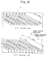
- Fig. 10 shows an example of a record pattern of another embodiment according to the present invention.
- a tracking detection signal (frequency f2) with any length is placed at intervals of a predetermined number of record tracks so that crosstalks are not detected at the same time (for example, every four record tracks).
- a first identification signal (frequency f1) is placed on a record track A1 which is one of just adjacent tracks of a track B1 where the tracking detection signal is recorded.
- a second identification signal (frequency f2) is placed on a record track A2 which is the other adjacent track of the track B1.
- arrow mark x represents the scanning direction of the rotary heads
- y represents the phase direction of the tape.
- a first identification signal (frequency f1) with a length of for example 2 Dx is placed in a predetermined region of a first record track A1 which is disposed at intervals of four record tracks.
- a tracking detection signal (frequency f2) with a length of for example 4 Dx is placed in a predetermined region of a second record track B1 just adjacent to the record track A1.
- a second identification signal (frequency f1) with a length of for example 4 Dx is placed in a predetermined region of a third record track A2. However, these signals (frequencies f1 and f2) are not placed on a fourth record track B2.
- the first to fourth record tracks A1 to B2 are repeatedly placed at intervals of four tracks.
- first and second identification signals and a tracking detection signal which are same as those on the head leaving side are placed in the reverse relation thereof.
- a first identification signal is determined from reproduction signals of the first record track A1 on the head entering side. After the first identification signal becomes low and a relevant rotary head scans a region of 2 Dx, the level of a crosstalk of a tracking detection signal is detected. Next, a second identification signal is determined from reproduction signals on the third record track A2. After the second identification signal becomes low and the head scans the region of 2 Dx, the level of a crosstalk of a tracking detection signal is detected. A tracking control operation is performed so that these detected levels match.
- the tracking control operation can be performed in such a manner.
- a tracking detection signal is placed at intervals of for example four record tracks.
- crosstalks of two tracking detection signals are not detected at the same time.
- the length of this tracking detection signal can be freely set (by a monostable multivibrator 46).
- the length of a tracking detection signal is 4 Dx.
- the length of the tracking detection signal can be longer than 4 Dx.
- a tracking detection area AFT area
- the maximum length of this signal is accordingly restricted.
- the length of this signal can be longer than 2 Dx.
- the length of a tracking detection signal can be freely set.
- the requirement for the compatibility of products is alleviated.
- the restrictions on the production of products such as an increase of the number of adjustment steps and an decrease of the yield of the products can be removed.
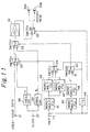
- Fig. 11 shows the construction of an example of a recording apparatus for recording the above-mentioned record pattern.
- reference numeral 31 is an input terminal to which record signals such as video data and audio data are supplied.
- the record signals received from the input terminal 31 are supplied to a record amplifier 34 through selector switches 32 and 33.
- the output signal of the record amplifier 34 is supplied to rotary heads 36A and 36B through a head selection switch 35.
- the clock signal received from the terminal 37 is supplied to frequency division circuits 38 and 39.
- Reference numeral 40 is a terminal to which switching pulses (SWP) in synchronization with the rotations of the rotary heads 36A and 36B are supplied.
- a signal received from this terminal 40 is supplied to a T1 monostable multivibrator (monomulti) 41.
- the monomulti 41 forms a timing equivalent to each pulse duration of the first and second identification signals.
- the output signal of the monomulti 41 is supplied to both T2 and T3 monostable multivibrators (monomulties) 12 and 13.
- the T2 and T3 monomulties 42 and 43 form timings equivalent to the pulse durations of first and second identification signals, respectively.
- One of the output signals of the monomulties 42 and 43 are selected by a selector switch 44.
- the output signal of the selector switch 44 is supplied to a control terminal of the selector switch 32.
- the signal received from the terminal 40 is supplied to a T4 monostable multivibrator (monomulti) 45.
- the monomulti 45 forms a timing equivalent to the pulse duration of the tracking detection signal.
- the output signal of the monomulti 45 is supplied to a T5 monostable multivibrator (monomulti) 46.
- the monomulti 46 forms a timing equivalent to the pulse duration of the tracking detection signal.
- the output signal of the monomulti 46 is selected by a selector switch 47.
- the output signal of the selector switch 47 is supplied to a control terminal of a selector switch 33.
- the signal received from the terminal 40 is supplied to a 1/2 frequency division circuit 48.
- the output signal of the frequency division circuit 48 causes the selector switches 44 and 45 to be switched.
- the signal received from the terminal 40 causes the head selection switch 35 to be switched.
- the 1/2 frequency division circuit 48 outputs a signal shown at B in Fig. 12.
- the monomulti 41 forms a signal equivalent to each pulse duration of first and second identification signals as shown at C in Fig. 12.
- the monomulties 42 and 43 form signals equivalent to the pulse durations of the first and second identification signals as shown at D and E in Fig. 12, respectively.
- the selector switch 44 selects one of these signals and forms a signal as shown at F in Fig. 12.
- the monomulti 45 forms a signal equivalent to the pulse duration of the tracking detection signal as shown at G in Fig. 12.
- the monomulti 46 forms a signal equivalent to the pulse duration of the tracking detection signal as shown at H in Fig. 12.
- the selector switch 47 selects this signal and forms a signal as shown at I in Fig. 12.
- the output signals of the selector signals 44 and 47 are supplied to the selector switches 32 and 33, respectively.
- the selector switch 33 outputs a signal as shown at J in Fig. 12.
- a first identification signal (frequency f1) with a length of for example 2 Dx is placed in a predetermined region of a first record track B1.
- a track detection signal (frequency f2) with a length of for example 4 Dx is placed in a predetermined region of a second record track A1.
- a second identification signal (frequency f1) with a length of for example 4 Dx is placed in a predetermined region of a third record track B2.
- these signals (frequencies f1 and f2) are not placed.
- the first to fourth record tracks B1 to A2 are repeatedly placed at intervals of four record tracks.
- the times T1 to T5 of the monomulties 41 to 46 are set according to the record forma on a magnetic tape for use.
- Fig. 13 shows the construction of an example of a reproducing apparatus for reproducing the above-mentioned record pattern so as to perform a tracking control operation.
- the output signals of rotary heads 51A and 51B are supplied to a head selection switch 22.
- Reference numeral 53 is a terminal to which switching pulses (SWP) in synchronization with the rotations of the rotary heads 51A and 51B are supplied.
- SWP switching pulses
- the output signal of the terminal 53 causes the selection switch 52 to be switched.
- the output signal of the selection switch 52 is supplied to an output terminal 55 through a reproduction amplifier 54.
- the output signal of the reproduction amplifier 54 is supplied to a band-pass filter (BPF) 56.
- BPF 56 outputs a signal with a frequency f2.
- the output signal of the BPF 56 is supplied to an envelop detection circuit 57.
- the output signal of the envelop detection circuit 57 is supplied to both sample hold circuits 59 and 60 through a low-pass filter (LPF) 58.
- LPF low-pass filter
- the output signal of the reproduction amplifier 54 is supplied to a band-pass filter (BPF) 61.
- the BPF 61 outputs a signal with a frequency f1.
- the output signal of the BPF 61 is supplied to an envelop detection circuit 62.
- the output signal of the envelop detection circuit 62 is supplied to a level comparison circuit 64 through a low-pass filter (LPF) 63.
- the level comparison circuit 64 outputs a signal which exceeds a predetermined level.
- this signal is supplied to a T6 monostable multivibrator (monomulti) 65.
- the output signal of the monomulti 65 is supplied to a monostable multivibrator (monomulti) 66.
- the monomulti 66 generates sampling pulses.
- the output signal of the monomulti 66 is supplied to AND circuits 67 and 68.
- the signal is supplied to a T7 monostable multivibrator (monomulti) 69.
- the output signal of the monomulti 69 is supplied to a monostable multivibrator (monomulti) 70.
- the monomulti 70 generates gate pulses.
- the output signal of the monomulti 70 is supplied to the AND circuit 67.
- a sampling pulse of the AND circuit 67 is supplied to the sample hole circuit 60.
- this signal is supplied to a T8 monostable multivibrator (monomulti) 71.
- the output signal of the monomulti 71 is supplied to a monostable multivibrator (monomulti) 72.
- the monomulti 72 generates gate pulses.
- the output signal of the monomulti 72 is supplied to the AND circuit 78.
- a sampling pulse of the AND circuit 78 is supplied to the sample hold circuit 59.
- the output signals of the sample hold circuits 59 and 60 are supplied to a differential circuit 73.
- the output signal of the differential circuit 73 is supplied to an ATF error output terminal through an amplifier 74.
- the band-pass filter 61 outputs a signal as shown at B in Fig. 14.
- the band-pass filter 56 outputs a signal as shown at C in Fig. 14.
- the level comparison circuit 64 outputs a signal as shown at D in Fig. 14.
- the monomulti 66 outputs a signal as shown at E in Fig. 14.
- the monomulti 69 outputs a signal as shown at F in Fig. 14.
- the monomulti 70 outputs a signal as shown at G in Fig. 14.
- the AND circuit 67 outputs a sampling pulse as shown at H in Fig. 14.
- the monomulti 71 outputs a signal as shown at I in Fig. 14.
- the monomulti 72 outputs a signal as shown at J in Fig. 14.
- the AND circuit 68 outputs a sampling pulse as shown at K in Fig. 14.
- a crosstalk of the tracking detection signal (frequency f2) is sampled and held by the circuit 60.
- a crosstalk of the tracking detection signal (frequency f2) is sampled and held by the circuit 59.
- the tracking control operation is performed so that the levels of these crosstalks match.
- the operations for the record tracks B1 and B2 are repeated at intervals of four record tracks.
- the times T6 to T8 of the monomulties 65 to 71 are set according to the record format of the tape for use.
- Fig. 15 shows a record format for a high record density at a low tape traveling speed.
- the track offset Dx is short.
- the length of a first identification signal (frequency f1) is for example 3 Dx
- the length of a tracking detection signal (frequency f2) is for example 6 Dx
- the length of a second identification signal (frequency f1) is for example 5 Dx.
- the times T1 to T8 of the monomulties 41 to 46 of the recording apparatus and the monomulties 65 to 71 of the reproducing apparatus are set according to the record format of a tape for use.
- Pilot signals are recorded in ATF areas basically for a tracking control operation.
- the reproduction outputs can be used as a reference for defining an after-record position in the data area of each track.
- the frequency f1 of a pilot signal is lowered as with the present invention, because of reasons such as decreasing the number of recordable waves and varying the phase of the separation low-pass filter, an after-record position cannot be precisely defined.
- a timing signal for defining an after-record position can be recorded in a region of an ATF area where pilot signals are not recorded.
- each pilot signal can be satisfactorily widened without a tradeoff of an increase of the length of an ATF area, a tracking error can be stably detected.
- different frequencies for pilot signals are used, even if a head scans a different azimuth track, a correct tracking state can be quickly obtained.
- the length of a tracking detection signal can be freely set.
- the requirement for the compatibility of products is alleviated.
- the restrictions on the production of products such as an increase of the number of adjustment steps and an decrease of the yield of the products can be removed.
Landscapes
- Adjustment Of The Magnetic Head Position Track Following On Tapes (AREA)
Applications Claiming Priority (4)
| Application Number | Priority Date | Filing Date | Title |
|---|---|---|---|
| JP4089435A JPH05258404A (ja) | 1992-03-13 | 1992-03-13 | 回転ヘッド型記録装置のトラッキング制御装置 |
| JP89435/92 | 1992-03-13 | ||
| JP114802/92 | 1992-05-07 | ||
| JP4114802A JPH05314444A (ja) | 1992-05-07 | 1992-05-07 | 記録方法、記録装置、再生装置、及び、記録再生装置 |
Publications (1)
| Publication Number | Publication Date |
|---|---|
| EP0560367A1 true EP0560367A1 (fr) | 1993-09-15 |
Family
ID=26430857
Family Applications (1)
| Application Number | Title | Priority Date | Filing Date |
|---|---|---|---|
| EP93103964A Withdrawn EP0560367A1 (fr) | 1992-03-13 | 1993-03-11 | Appareil pour rechercher la piste dans une unité d'enregistrement avec type de tête rotatif |
Country Status (2)
| Country | Link |
|---|---|
| US (1) | US5402281A (fr) |
| EP (1) | EP0560367A1 (fr) |
Cited By (1)
| Publication number | Priority date | Publication date | Assignee | Title |
|---|---|---|---|---|
| US5412520A (en) * | 1992-10-06 | 1995-05-02 | Sony Corporation | Tracking control which avoids lock-up for rotary head reproducing apparatus and which senses whether a trucking control signal is absent for a predetermined time |
Families Citing this family (5)
| Publication number | Priority date | Publication date | Assignee | Title |
|---|---|---|---|---|
| JPH07105597A (ja) * | 1993-10-05 | 1995-04-21 | Matsushita Electric Ind Co Ltd | 磁気記録装置の記録再生方法及びトラッキング方法 |
| US6005741A (en) * | 1993-05-28 | 1999-12-21 | Canon Kabushiki Kaisha | Reproducing apparatus using pilot signal crosstalk for tracking control and using pilot signals to eliminate a back lock condition |
| JP3420286B2 (ja) * | 1993-05-28 | 2003-06-23 | キヤノン株式会社 | 記録再生装置 |
| JPH06349159A (ja) * | 1993-06-01 | 1994-12-22 | Canon Inc | トラッキング制御装置 |
| KR200148355Y1 (ko) * | 1994-11-25 | 1999-06-15 | 류공현 | 멸균,건조기능 및 선반이 구비된 싱크대 서랍 |
Citations (2)
| Publication number | Priority date | Publication date | Assignee | Title |
|---|---|---|---|---|
| DE2753814B2 (de) * | 1976-12-03 | 1981-07-09 | Matsushita Electric Industrial Co., Ltd., Kadoma, Osaka | Verfahren zum Einstellen eines Videoaufnahme- und wiedergabegeräts mit einem rotierenden Magnetkopf |
| EP0380284A1 (fr) * | 1989-01-24 | 1990-08-01 | Sony Corporation | Appareil et procédé de production de signaux de commande de suivi de piste |
Family Cites Families (3)
| Publication number | Priority date | Publication date | Assignee | Title |
|---|---|---|---|---|
| EP0138210A3 (fr) * | 1983-10-14 | 1986-02-05 | Hitachi, Ltd. | Appareil d'enregistrement ou de reproduction magnétique du type à tête rotative et méthode pour produire des signaux de commande de suivi de piste |
| JPH0693304B2 (ja) * | 1985-10-08 | 1994-11-16 | ソニー株式会社 | トラツキング制御装置 |
| JPH0426947A (ja) * | 1990-05-21 | 1992-01-30 | Sony Corp | 再生方法 |
-
1993
- 1993-03-11 EP EP93103964A patent/EP0560367A1/fr not_active Withdrawn
- 1993-03-11 US US08/029,583 patent/US5402281A/en not_active Expired - Fee Related
Patent Citations (2)
| Publication number | Priority date | Publication date | Assignee | Title |
|---|---|---|---|---|
| DE2753814B2 (de) * | 1976-12-03 | 1981-07-09 | Matsushita Electric Industrial Co., Ltd., Kadoma, Osaka | Verfahren zum Einstellen eines Videoaufnahme- und wiedergabegeräts mit einem rotierenden Magnetkopf |
| EP0380284A1 (fr) * | 1989-01-24 | 1990-08-01 | Sony Corporation | Appareil et procédé de production de signaux de commande de suivi de piste |
Cited By (1)
| Publication number | Priority date | Publication date | Assignee | Title |
|---|---|---|---|---|
| US5412520A (en) * | 1992-10-06 | 1995-05-02 | Sony Corporation | Tracking control which avoids lock-up for rotary head reproducing apparatus and which senses whether a trucking control signal is absent for a predetermined time |
Also Published As
| Publication number | Publication date |
|---|---|
| US5402281A (en) | 1995-03-28 |
Similar Documents
| Publication | Publication Date | Title |
|---|---|---|
| KR900002237B1 (ko) | 회전헤드형 자기기록 재생장치 및 그것을 위한 트랙킹 제어신호 발생방법 | |
| EP0171266A2 (fr) | Enregistrement de signaux d'information numériques | |
| JPS6321247B2 (fr) | ||
| JPH0426947A (ja) | 再生方法 | |
| EP0560367A1 (fr) | Appareil pour rechercher la piste dans une unité d'enregistrement avec type de tête rotatif | |
| KR100249289B1 (ko) | 정보신호기록방법, 자기테이프, 및정보신호기록 및 재생방법 | |
| KR970000642B1 (ko) | 정보 기록 재생장치 | |
| JPS5937785A (ja) | 磁気録画再生装置 | |
| US5177649A (en) | Information signal recording apparatus for recording pilot signals on particular areas | |
| KR920001127B1 (ko) | 기록모우드 판별 절환방법 | |
| EP0316954B1 (fr) | Méthode de reproduction pour enregistreur à bande du genre à téte rotative | |
| US5978171A (en) | Information signal reproducing apparatus with diverse mode tracking control | |
| CN1090424C (zh) | 信号再现设备 | |
| JP2646958B2 (ja) | 情報信号の記録再生装置 | |
| JP2646960B2 (ja) | 情報信号の記録されたテープ | |
| JPH0610903B2 (ja) | スロ−再生用トラツキング制御装置 | |
| JP2646959B2 (ja) | 情報信号の再生装置 | |
| JP2570773B2 (ja) | トラッキング方式 | |
| JP2529443B2 (ja) | 磁気記録再生装置のトラッキング制御装置 | |
| JP2501315B2 (ja) | 磁気記録再生装置 | |
| EP0357352A2 (fr) | Appareil d'enregistrement/de reproduction de signaux vidéo | |
| JPH0664721B2 (ja) | パイロツト信号記録再生方法 | |
| JPH05258404A (ja) | 回転ヘッド型記録装置のトラッキング制御装置 | |
| JPH0334607B2 (fr) | ||
| JPH0311596B2 (fr) |
Legal Events
| Date | Code | Title | Description |
|---|---|---|---|
| PUAI | Public reference made under article 153(3) epc to a published international application that has entered the european phase |
Free format text: ORIGINAL CODE: 0009012 |
|
| AK | Designated contracting states |
Kind code of ref document: A1 Designated state(s): DE FR GB NL |
|
| 17P | Request for examination filed |
Effective date: 19940217 |
|
| 17Q | First examination report despatched |
Effective date: 19960819 |
|
| 18D | Application deemed to be withdrawn |
Effective date: 19961231 |