EP0560735A1 - Vorrichtung zum automatischen Positionieren von Strümpfen in einer Strumpfhosennähmaschine - Google Patents
Vorrichtung zum automatischen Positionieren von Strümpfen in einer Strumpfhosennähmaschine Download PDFInfo
- Publication number
- EP0560735A1 EP0560735A1 EP93830068A EP93830068A EP0560735A1 EP 0560735 A1 EP0560735 A1 EP 0560735A1 EP 93830068 A EP93830068 A EP 93830068A EP 93830068 A EP93830068 A EP 93830068A EP 0560735 A1 EP0560735 A1 EP 0560735A1
- Authority
- EP
- European Patent Office
- Prior art keywords
- bow
- rod
- arms
- stockings
- arm
- Prior art date
- Legal status (The legal status is an assumption and is not a legal conclusion. Google has not performed a legal analysis and makes no representation as to the accuracy of the status listed.)
- Granted
Links
- 238000009958 sewing Methods 0.000 title claims abstract description 10
- 238000000605 extraction Methods 0.000 claims abstract description 9
- 238000001514 detection method Methods 0.000 claims abstract description 8
- 239000004677 Nylon Substances 0.000 claims abstract description 7
- 229920001778 nylon Polymers 0.000 claims abstract description 7
- 230000003287 optical effect Effects 0.000 claims description 8
- 230000006835 compression Effects 0.000 claims description 2
- 238000007906 compression Methods 0.000 claims description 2
- 238000009434 installation Methods 0.000 claims description 2
- 230000003213 activating effect Effects 0.000 claims 1
- 238000004519 manufacturing process Methods 0.000 description 7
- 230000015572 biosynthetic process Effects 0.000 description 2
- 238000010276 construction Methods 0.000 description 2
- 230000001143 conditioned effect Effects 0.000 description 1
- 239000004744 fabric Substances 0.000 description 1
- 238000003780 insertion Methods 0.000 description 1
- 230000037431 insertion Effects 0.000 description 1
- 238000012423 maintenance Methods 0.000 description 1
Images



Classifications
-
- D—TEXTILES; PAPER
- D05—SEWING; EMBROIDERING; TUFTING
- D05B—SEWING
- D05B23/00—Sewing apparatus or machines not otherwise provided for
- D05B23/007—Sewing units for assembling parts of knitted panties or closing the stocking toe part
Definitions
- the present invention relates to a device for the automatic positioning of the stockings in a machine for the formation of tights, with the automatic detection of the garter line.
- the two stockings to be sewn together to form a pantyhose are first of all threaded on a pair of overlapping twin shapes, then they are aligned vertically and placed side by side so as to obtain the correspondence between the elastic edges and the garter lines of the two bottoms.
- said longitudinal section leads to the determination of two edges of equal length and positioned identically with respect to the line of garter.
- the juxtaposed edges of the two stockings are sewn together and form a pantyhose: the seam is executed over the entire length of the edges.
- devices which are equipped with optical sensors sensitive to the difference in density between the fabric of the lower leg and that of the body tissue.
- the two stockings, on which to work to form a pantyhose, are strung randomly on the two paired shapes.
- the means for positioning the elastic edges grip the latter and introduce them fully onto the forms and until the garter line is threaded onto the forms and to allow thus their detection by the corresponding sensors.
- the sensors for detecting the elastic edge of the stockings move towards and to a predetermined alignment position and the associated means for positioning said elastic edges make it possible to transfer them to said alignment position.
- the bodies of the stockings are extended, that is to say without folds, over a predetermined length and with the elastic edges and the garter lines aligned vertically so as to allow the execution of the operation of successive cutting, correctly.
- this known positioning device has certain drawbacks. The most important of these is the need to move the elastic edge and the leg of each stocking in two distinct phases and by means of different positioning members, which must work separately. And this implies a greater complexity of construction of the machine, to the detriment of the economy of production and exercise thereof. Furthermore, because of the construction complexity of said known device, the reliability of the machine which is equipped with it turns out to be greatly reduced, which leads to more frequent maintenance operations and longer downtimes.
- Another disadvantage consists in the fact that the overall time necessary for the production of a pantyhose turns out to be strongly conditioned by the speed of execution of the abovementioned operations of positioning the stockings on the corresponding shapes, so that, if one wishes to increase maximum production speed of tights and taking into account that in the current state, it is not possible to further reduce the cutting and sewing times of the stockings, it is not possible to obtain extremely narrow margins of tolerance in the detection of garter lines, which leads to inaccuracies in the production of tights.
- the object of the present invention is to eliminate the drawbacks mentioned without increasing the length of the shapes.
- the advantages obtained thanks to the present invention essentially consist in the fact that it is possible to obtain the tightening of the body and of the upper zone of the legs of each stocking in a single phase and with the same means of movement; which the production time of a pantyhose turns out to be considerably reduced or otherwise that, for the same time used, the speed of movement of the stockings is greatly reduced, in favor of the precision in the detection of the garter lines and, consequently , to the benefit of the quality of the tights produced; that the proposed device is simple to make and therefore economical and reliable even after very long continuous use; that the machines for the production of tights currently available can be easily and quickly fitted with a device according to the invention.
- FIG. 1 shows a plan view, partially in section, of a machine clamp for sewing tights, equipped with a device for positioning the stocking in accordance with the invention
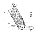
- Fig.2 shows the perspective view of the device of Fig. 1 with the tensioning bow in the retraction position
- Fig. 3 shows the device of FIG. 1 with the tensioning bow in the extraction position
- Fig. 4 shows the detailed axonometric view, partially in section, of the drive and guide means of the tensioning bow of the device of FIG.
- Fig. 5 shows the plan view, in section, of an alternative embodiment of the actuation means of the tensioning bow
- Figs. 6A and 6B show the plan view and, respectively, axonometric view of the actuation means of the tensioning arch according to another embodiment.
- a device for positioning the stockings in a machine for sewing tights with an optical sensor (18) for the detection of the garter line and comprising two paired forms of support for the stockings, each of the forms having two horizontal articulated arms (10) whose points are extended and connected by means of a bow (7) produced with a nylon thread and which is coplanar with the arm (10) and has the convexity directed towards the machine, provides that said bow (7) has its legs (71) housed in a sliding manner inside the arms (10) of the corresponding shape in their longitudinal direction between two positions , one of maximum retraction and the other of maximum extraction, to allow the bottom to be stretched out and before the form, and that said optical sensor (18) is in a position such that its light beam them vertical intercepts the garter line (17) in the area stretched by said bow (7) and therefore outside and before the form.
- the compressed air supplied by means of the connector (8) can advantageously be drawn from the same installation for the compression of the air with which each pantyhose sewing machine is equipped.
- the rods (4) comprise a stop element (14) on the side opposite to that of the guide ring (3): said stop element (14) being intended to be pushed towards the inside of the arms (10) by a pusher (20), thereby causing the bow (7) to exit relative to the arms (10).
- the operation is as follows.
- said tensioning bow (7) is rigidly fixed to only one of the rods (4), to allow its actuation by acting on only one of its legs (71) and therefore making provision to equip only one of the arms (10) of the form (13) with said drive and guide means: the other arm of the form being simply pierced longitudinally to allow the sliding of the other leg of the bow (7) when the latter is extracted or retracted.
- Attaching the arch (7) to one of the rods (4) has proven to be particularly advantageous for preventing the bow (7) from remaining in the extraction position by deforming into a rosette when the arms (10,30 ) of the form (13) are separated before sewing the tights.
Landscapes
- Engineering & Computer Science (AREA)
- Textile Engineering (AREA)
- Sewing Machines And Sewing (AREA)
- Socks And Pantyhose (AREA)
Applications Claiming Priority (2)
| Application Number | Priority Date | Filing Date | Title |
|---|---|---|---|
| ITFI920067A IT1259630B (it) | 1992-03-13 | 1992-03-13 | Dispositivo per il posizionamento automatico delle claze in macchina per cucire collants |
| ITFI920067 | 1992-03-13 |
Publications (2)
| Publication Number | Publication Date |
|---|---|
| EP0560735A1 true EP0560735A1 (de) | 1993-09-15 |
| EP0560735B1 EP0560735B1 (de) | 1995-10-25 |
Family
ID=11350012
Family Applications (1)
| Application Number | Title | Priority Date | Filing Date |
|---|---|---|---|
| EP93830068A Expired - Lifetime EP0560735B1 (de) | 1992-03-13 | 1993-02-24 | Vorrichtung zum automatischen Positionieren von Strümpfen in einer Strumpfhosennähmaschine |
Country Status (7)
| Country | Link |
|---|---|
| US (1) | US5309853A (de) |
| EP (1) | EP0560735B1 (de) |
| JP (1) | JP2542322B2 (de) |
| CA (1) | CA2091532A1 (de) |
| DE (1) | DE69300688T2 (de) |
| IT (1) | IT1259630B (de) |
| MX (1) | MX9301383A (de) |
Cited By (1)
| Publication number | Priority date | Publication date | Assignee | Title |
|---|---|---|---|---|
| EP0630999A1 (de) * | 1993-06-25 | 1994-12-28 | SOLIS S.r.l. | Verfahren und Vorrichtung, um zwei schlauchförmige Produkte auf einer vorbestimmten Position auf einem entsprechenden Träger anzuordnen |
Families Citing this family (1)
| Publication number | Priority date | Publication date | Assignee | Title |
|---|---|---|---|---|
| IT1262541B (it) * | 1993-10-18 | 1996-07-02 | Solis Srl | Dispositivo per il posizionamento della porzione del piede di manufatti tubolari a maglia |
Citations (4)
| Publication number | Priority date | Publication date | Assignee | Title |
|---|---|---|---|---|
| US3126134A (en) * | 1964-03-24 | Hose seam flattening device | ||
| US3197094A (en) * | 1962-08-01 | 1965-07-27 | Doctor E Fowler | Power operated hosiery extension machine |
| US4192242A (en) * | 1977-04-02 | 1980-03-11 | Detexomat Machinery Limited | Hosiery toe closers |
| US4374501A (en) * | 1980-07-18 | 1983-02-22 | Consolidated Foods Corporation | Garment toe closing assembly |
Family Cites Families (1)
| Publication number | Priority date | Publication date | Assignee | Title |
|---|---|---|---|---|
| JPH03173597A (ja) * | 1989-11-30 | 1991-07-26 | Takatori Haitetsuku:Kk | 股上縫製機におけるパンティストッキング生地の自動位置決装置 |
-
1992
- 1992-03-13 IT ITFI920067A patent/IT1259630B/it active IP Right Grant
-
1993
- 1993-02-24 DE DE69300688T patent/DE69300688T2/de not_active Expired - Fee Related
- 1993-02-24 EP EP93830068A patent/EP0560735B1/de not_active Expired - Lifetime
- 1993-03-11 CA CA002091532A patent/CA2091532A1/en not_active Abandoned
- 1993-03-12 US US08/030,570 patent/US5309853A/en not_active Expired - Fee Related
- 1993-03-12 MX MX9301383A patent/MX9301383A/es not_active Application Discontinuation
- 1993-03-15 JP JP5080035A patent/JP2542322B2/ja not_active Expired - Lifetime
Patent Citations (4)
| Publication number | Priority date | Publication date | Assignee | Title |
|---|---|---|---|---|
| US3126134A (en) * | 1964-03-24 | Hose seam flattening device | ||
| US3197094A (en) * | 1962-08-01 | 1965-07-27 | Doctor E Fowler | Power operated hosiery extension machine |
| US4192242A (en) * | 1977-04-02 | 1980-03-11 | Detexomat Machinery Limited | Hosiery toe closers |
| US4374501A (en) * | 1980-07-18 | 1983-02-22 | Consolidated Foods Corporation | Garment toe closing assembly |
Cited By (1)
| Publication number | Priority date | Publication date | Assignee | Title |
|---|---|---|---|---|
| EP0630999A1 (de) * | 1993-06-25 | 1994-12-28 | SOLIS S.r.l. | Verfahren und Vorrichtung, um zwei schlauchförmige Produkte auf einer vorbestimmten Position auf einem entsprechenden Träger anzuordnen |
Also Published As
| Publication number | Publication date |
|---|---|
| IT1259630B (it) | 1996-03-25 |
| ITFI920067A0 (it) | 1992-03-13 |
| JPH06205886A (ja) | 1994-07-26 |
| EP0560735B1 (de) | 1995-10-25 |
| JP2542322B2 (ja) | 1996-10-09 |
| ITFI920067A1 (it) | 1993-09-13 |
| DE69300688T2 (de) | 1996-07-04 |
| CA2091532A1 (en) | 1993-09-14 |
| DE69300688D1 (de) | 1995-11-30 |
| US5309853A (en) | 1994-05-10 |
| MX9301383A (es) | 1994-08-31 |
Similar Documents
| Publication | Publication Date | Title |
|---|---|---|
| CH640020A5 (fr) | Procede et machine a coudre pour inserer un ruban elastique aux angles d'un drap-housse. | |
| FR2638148A1 (fr) | Traceur de courbes a action progressive comportant un frein pour un rouleau debiteur de papier | |
| EP0560735B1 (de) | Vorrichtung zum automatischen Positionieren von Strümpfen in einer Strumpfhosennähmaschine | |
| CH677509A5 (de) | ||
| EP0630999B1 (de) | Verfahren und Vorrichtung, um zwei schlauchförmige Produkte auf einer vorbestimmten Position auf einem entsprechenden Träger anzuordnen | |
| EP2009996A1 (de) | Automatische maschine zum bilden eines knotens unter verwendung eines bindfadenendes einer röhrenförmigen hülle zu ihrem verschliessen durch einschnüren beim festziehen des knotens | |
| FR2467902A1 (fr) | Dispositif pour la mise automatique en position d'une piece de vetement en vue de l'execution d'une couture | |
| FR2499243A1 (fr) | Dispositif pour la mesure ou le controle de la tension d'une courroie | |
| EP0533637A1 (de) | Maschine zum automatischen Nähen der Fussspitzen zweier Strümpfe, insbesondere von Strumpfhosen | |
| FR2510150A1 (fr) | Frein de trame pour machine a tisser sans navette | |
| FR2461045A1 (fr) | Machine circulaire pour bas et similaires avec tambour a cames et tambour programmeur montes coaxialement au cylindre a aiguilles | |
| EP0636730B1 (de) | Verfahren und Vorrichtung zur automatischen Positionierung von Strümpfen in einer Maschine, um Strumpfhosen zu bilden | |
| EP0648880A1 (de) | Vorrichtung zum Positionieren des Fussteils eines schlauchförmig gestrickten Produktes | |
| FR2596701A3 (fr) | Appareil pour la preparation de poignees adhesives pour porter des paquets | |
| FR2505885A1 (fr) | Dispositif pour introduire les extremites de fil de trame au bord du tissu dans un metier a tisser sans navette | |
| FR2542584A1 (fr) | Procede et installation pour retourner les slips | |
| BE1001681A5 (fr) | Appareil pour positionner une chaine de points dans une machine a coudre. | |
| FR2609294A1 (fr) | Dispositif pour sectionner et positionner une chaine de points de couture formant un point de chainette sur du tissu avec une machine a coudre | |
| FR2730377A3 (fr) | Dispositif de controle de nouage pour des appareils de liage dans des presses a balles | |
| FR2620652A1 (fr) | Procede et dispositif de positionnement et lacage d'un lien souple sur un support rigide tel qu'un carton | |
| EP0802271A1 (de) | Vorrichtung zum Nähen des Zehenteils von schlauchförmigen gestrickten Produkten | |
| CH582106A5 (en) | Twisting device for large dia. cables - having drawing and feed devices mounted on support moveable between winding up positions | |
| FR2557491A1 (fr) | Machine pour la coupe et la pose de troncons de ruban souple | |
| EP0071687A1 (de) | Bindevorrichtung für Rundballenpressen | |
| BE549132A (de) |
Legal Events
| Date | Code | Title | Description |
|---|---|---|---|
| PUAI | Public reference made under article 153(3) epc to a published international application that has entered the european phase |
Free format text: ORIGINAL CODE: 0009012 |
|
| AK | Designated contracting states |
Kind code of ref document: A1 Designated state(s): DE FR GB IT |
|
| 17P | Request for examination filed |
Effective date: 19931220 |
|
| 17Q | First examination report despatched |
Effective date: 19950331 |
|
| GRAA | (expected) grant |
Free format text: ORIGINAL CODE: 0009210 |
|
| AK | Designated contracting states |
Kind code of ref document: B1 Designated state(s): DE FR GB IT |
|
| REF | Corresponds to: |
Ref document number: 69300688 Country of ref document: DE Date of ref document: 19951130 |
|
| ITF | It: translation for a ep patent filed | ||
| GBT | Gb: translation of ep patent filed (gb section 77(6)(a)/1977) |
Effective date: 19960106 |
|
| PLBE | No opposition filed within time limit |
Free format text: ORIGINAL CODE: 0009261 |
|
| STAA | Information on the status of an ep patent application or granted ep patent |
Free format text: STATUS: NO OPPOSITION FILED WITHIN TIME LIMIT |
|
| 26N | No opposition filed | ||
| REG | Reference to a national code |
Ref country code: GB Ref legal event code: IF02 |
|
| PGFP | Annual fee paid to national office [announced via postgrant information from national office to epo] |
Ref country code: DE Payment date: 20060216 Year of fee payment: 14 |
|
| PGFP | Annual fee paid to national office [announced via postgrant information from national office to epo] |
Ref country code: GB Payment date: 20060222 Year of fee payment: 14 |
|
| PGFP | Annual fee paid to national office [announced via postgrant information from national office to epo] |
Ref country code: FR Payment date: 20060227 Year of fee payment: 14 |
|
| GBPC | Gb: european patent ceased through non-payment of renewal fee |
Effective date: 20070224 |
|
| REG | Reference to a national code |
Ref country code: FR Ref legal event code: ST Effective date: 20071030 |
|
| PG25 | Lapsed in a contracting state [announced via postgrant information from national office to epo] |
Ref country code: DE Free format text: LAPSE BECAUSE OF NON-PAYMENT OF DUE FEES Effective date: 20070901 |
|
| PG25 | Lapsed in a contracting state [announced via postgrant information from national office to epo] |
Ref country code: GB Free format text: LAPSE BECAUSE OF NON-PAYMENT OF DUE FEES Effective date: 20070224 Ref country code: FR Free format text: LAPSE BECAUSE OF NON-PAYMENT OF DUE FEES Effective date: 20070228 |
|
| PGFP | Annual fee paid to national office [announced via postgrant information from national office to epo] |
Ref country code: IT Payment date: 20080228 Year of fee payment: 16 |
|
| PG25 | Lapsed in a contracting state [announced via postgrant information from national office to epo] |
Ref country code: IT Free format text: LAPSE BECAUSE OF NON-PAYMENT OF DUE FEES Effective date: 20090224 |