EP0563643A2 - Machine pour encartonner - Google Patents
Machine pour encartonner Download PDFInfo
- Publication number
- EP0563643A2 EP0563643A2 EP93103960A EP93103960A EP0563643A2 EP 0563643 A2 EP0563643 A2 EP 0563643A2 EP 93103960 A EP93103960 A EP 93103960A EP 93103960 A EP93103960 A EP 93103960A EP 0563643 A2 EP0563643 A2 EP 0563643A2
- Authority
- EP
- European Patent Office
- Prior art keywords
- cartoning
- cartoning device
- carton
- blank
- palletizing
- Prior art date
- Legal status (The legal status is an assumption and is not a legal conclusion. Google has not performed a legal analysis and makes no representation as to the accuracy of the status listed.)
- Granted
Links
Images


Classifications
-
- B—PERFORMING OPERATIONS; TRANSPORTING
- B65—CONVEYING; PACKING; STORING; HANDLING THIN OR FILAMENTARY MATERIAL
- B65B—MACHINES, APPARATUS OR DEVICES FOR, OR METHODS OF, PACKAGING ARTICLES OR MATERIALS; UNPACKING
- B65B5/00—Packaging individual articles in containers or receptacles, e.g. bags, sacks, boxes, cartons, cans, jars
- B65B5/02—Machines characterised by incorporation of means for making the containers or receptacles
- B65B5/024—Machines characterised by incorporation of means for making the containers or receptacles for making containers from preformed blanks
-
- B—PERFORMING OPERATIONS; TRANSPORTING
- B65—CONVEYING; PACKING; STORING; HANDLING THIN OR FILAMENTARY MATERIAL
- B65B—MACHINES, APPARATUS OR DEVICES FOR, OR METHODS OF, PACKAGING ARTICLES OR MATERIALS; UNPACKING
- B65B43/00—Forming, feeding, opening or setting-up containers or receptacles in association with packaging
- B65B43/12—Feeding flexible bags or carton blanks in flat or collapsed state; Feeding flat bags connected to form a series or chain
- B65B43/14—Feeding individual bags or carton blanks from piles or magazines
- B65B43/16—Feeding individual bags or carton blanks from piles or magazines by grippers
- B65B43/18—Feeding individual bags or carton blanks from piles or magazines by grippers by suction-operated grippers
- B65B43/185—Feeding individual bags or carton blanks from piles or magazines by grippers by suction-operated grippers specially adapted for carton blanks
Definitions
- the invention relates to a cartoning device with a cartoner for packaging cuboid objects in cartons, a device for feeding and setting up cardboard blanks which have a side wall area and associated bottom and top flaps, a device for inserting the objects to be packaged and a device for closing of the filled, filled cardboard blank under glueing.
- containers such as cigarette sticks are to be cartoned
- collecting the containers takes the most time.
- the cycle of their manufacture depends on the delivery of the objects to be grouped together, such as cigarette packs.
- cartoners who only carton certain containers, for example only containers made from packets of a certain type of cigarette, are not used optimally.
- the object of the invention is to provide a cartoning device of the type mentioned at the outset, which allows optimal use of the possible cartoning speed.
- This object is achieved in that several adjacent pallet stations for stacks of cardboard blanks, the side wall region of which is already closed all around, are provided with supporting pallets, wherein at least one removal gripper can be moved along the pallet stations for removing and depositing a carton blank in a set-up device, the set-up device a turret, which can be driven step by step and has cells, with associated folding elements for folding over the bottom and top flaps in the closed position and glueing heads, is connected downstream and objects to be packaged supplied by a conveyor can be inserted into a cell that is in the receiving position and contains a set-up box blank.
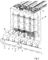
- Fig. 1 shows a schematic perspective of a device for cartoning stacks of packs.
- FIG. 2 shows an embodiment for a device for conveying bundles of packs for the device of FIG. 1.
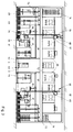
- Fig. 3 shows schematically an embodiment of a cartoning system with two devices for cartoning.
- Fig. 4 shows the system of Fig. 3 in a view rotated by 90 °.
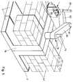
- FIG. 5 schematically shows a palletizing robot, in particular for a cartoning system according to FIG. 3.
- Pallets 3 with carton blanks 4 stacked thereon can each be conveyed via a plurality of parallel roller tables 2 branching off from a common conveyor line and consisting of a multiplicity of at least partially drivable rollers 1 up to one of a plurality of end positions located next to one another, adjacent to a feed side of a multiformat cartoner 5 .
- the cardboard blanks 4 are rectangular and glued in the later side wall region 6 of the cardboard in such a way that the side wall region 6 can be set up to form a cylinder with a rectangular cross section, while four cover and bottom flaps 7, 8 are movably connected to the side wall region 6 via fold lines.
- the carton blanks 4 are arranged in the respective stacks with the lid and bottom flaps 7, 8 in the direction of the multi-format cartoner 5.
- 4 different blank stacks A, B, C, D can be delivered by means of the pallets 3. It does not matter in which end position which carton blanks 4 are delivered, the delivery takes place according to the need for certain carton blanks 4 to free end positions, but more frequently needed but as close as possible to the multi-format cartoner 5.
- plungers 9 are provided below the respective roller table 2 and can be moved upwards between the rollers 1 in order to lift a stack of blanks of cardboard blanks 4 on a pallet 3 as a whole from the pallet 3 in the vertical direction.
- the lifted stack of blanks of cardboard blanks 4 is received by a level lift 10, which engages with two parallel support strips 11 on two opposite sides under the underside of the blank stack.
- the support strips 11 are vertically adjustable via chain drives or toothed belts 12 in order to always keep the top of the blank stack at the same height regardless of how many cardboard blanks 4 have been removed from the blank stack.
- the plungers 9 are returned under the roller table 2 so that the empty pallet 3 can be removed.
- a stop bar 14 which can be pivoted in the direction of the blank stack by means of a cylinder 13, while a fixed stop 15 is provided on the two remaining edges.
- the two stop bars 14 press the cardboard blanks 4 at the upper end of the stack of blanks by pivoting them inwards against the fixed stops 15, as a result of which the cardboard blanks 4 are slightly curved or shifted relative to one another so that they are separated from one another to facilitate gripping.
- a removal gripper 16 which is provided with a removal head 19 which has a plurality of suction cups 17 and can be moved vertically by means of a drive 18, for example in the form of a cylinder, is arranged to be movable along a horizontal rail 20.
- the removal gripper 16 removes the uppermost carton blank 4 of a blank stack via the suction cups 17 and transfers it to a set-up device 21.
- the set-up device 21 has a vertical set-up wall 22 and a stand-up set-up wall 23 which is at a distance from it and which is predominantly diagonally vertical and which is bent at the upper end practically without kinks into the horizontal.
- the two installation walls 22, 23 form a shaft narrowing downward between them.
- the distance between the set-up walls 22, 23 corresponds in the lower area to the later carton width.
- Suction cups 24 which can be moved vertically between the set-up walls 22, 23, for example by means of a carrier plate, serve to grip a side wall of the side wall area 6 of a cardboard blank 4 and to pull the cardboard blank 4 into the shaft between the two set-up walls 22, 23 in order to set up the cardboard blank 4 in this way that the side wall region 6 forms a cuboid-shaped receiving space which is open towards the bottom and top flaps 7, 8.
- a delivered cardboard blank 4 lies on one side after delivery to the erection device 21 on the practically horizontal, upper end section of the erection wall 23 and on the raised suction cups 24.
- a fixed edge for the respectively delivered cardboard blank 4 is formed by two setting angles 25, which are arranged adjacent to the multi-format cartoner 5 on the top of the set-up walls 22, 23.
- the contact surface for cardboard blanks of the set-up device 21 can be changed.
- the curved installation wall 23 is in the direction of the vertical installation wall 22 (for example by means of a compression spring 43 for smaller strokes, which at the same time causes the pre-tensioned cardboard blank 31 to be spring-loaded, or a cylinder) and / or two further setting angles 26 with respect to the setting angles 25 the distance can be changed, the setting angle 26 being horizontally displaceable via a setting plate 27 which is engaged by a cylinder 28 and which is guided horizontally.
- inwardly pivotable supports 30 are provided via cylinders 29 in the area occupied by these flaps when a carton blank 4 is placed on the mounting device 21, with a cylinder 29 with its associated support 30 the adjusting plate 27 is arranged for adjustment according to the cardboard blank length and can be moved therewith.
- the removal head 16 can also act for a moment on the upper layer of the carton blank 4 when the suction cups 24 act on the lower layer, as a result of which the two layers are pulled apart. This is at least for cardboard blanks 4 for square receptacle cross sections useful.
- the cardboard blanks 4 can also be set up with a differently designed set-up device, the one described above is particularly expedient because the cardboard blanks 4 have to be conveyed in the illustrated embodiment anyway in the vertical direction in order to be fed to the multi-format cartoner 5, and therefore the sequence of movements is not interrupted.
- the cardboard blank 31 set up in the set-up device 21 is transferred to the multi-format cartoner 5 by means of a transfer device (not shown), the lower edge of the vertical set-up wall 22 serving as a fixed edge.
- the multi-format cartoner 5 is designed as a turret 33 which is provided with a stepping drive 32 and which has a plurality of cells 34 which are offset by 90 ° in the exemplary embodiment and are open in the axial direction.
- the cells 34 of the revolver 33 have two adjacent stationary and two adjacent movable cell walls 35, 36, the movable cell walls 36 parallel to the opposite stationary cell wall 35 by means of a servo drive for adapting the receiving space of the respective cell 34 to the cross-sectional format of a cardboard blank 31 to be accommodated, which is inserted axially by means of the transfer device into a cell 34 in the receiving position (in the exemplary embodiment shown, the lower cell 34) can be displaced.
- the cell walls 36 are expediently or the like by a small stroke of approximately the order of 2 to 3 mm. spring-loaded inward to compensate for tolerances of the cardboard blanks 4. This can be achieved, for example, by designing the movable cell walls 36 as double walls with compression springs arranged between them.
- the multi-format cartoner 5 is provided with a gluing device 37, which comprises a hot glue container 38, from which hot glue is fed to two gluing heads 40 via corresponding feed lines 39.
- the glueing heads 40 are arranged along parallel rails 41 (which are arranged horizontally in the illustrated embodiment because the gluing takes place in the uppermost position) over one another Cylinder 42 can be moved along the open end faces of the cell 34 of the turret 33 in the gluing position.
- One of the rails 41 is fixed, while the other, according to the carton format, is adjustable in its distance from the first rail 41 via a cylinder 44 within a frame 45.
- Two opposite cell walls 35, 36 are provided with cutouts 46, which are open in the direction of the movable rail 41, so that the cell walls 35, 36 cannot hinder gluing if the carton height is less than the depth of the cells 34.
- cutouts 46 which are open in the direction of the movable rail 41, so that the cell walls 35, 36 cannot hinder gluing if the carton height is less than the depth of the cells 34.
- cells 34 which are correspondingly short can also be used in the axial direction, this can impair the support of the cardboard blank 32 that has been set up.
- Objects 47 to be packaged are delivered as packs of packs 48 in a quantity to be packaged in each case via a clocked conveyor belt 49.
- the conveyor belt 49 is provided with fixing devices 50 for the stack 48 of containers, the walls 51, 52 of which are aligned at the discharge end of the conveyor belt 49 with the cell 34 in the receiving position for the stack 48 of containers.
- the wall 51 of the fixing device 50 located at the rear in the conveying direction of the conveyor belt 49 serves as a fixed wall, since the lower edge of the cell 34 located in the receiving position for the stack 48 of packs is also the fixed edge thereof.
- the walls 52 can also be omitted. Then an optionally two-sided alignment movement for the bundle 48 at the end of the conveyor belt 49 before being pushed into a cell 34 may be expedient.
- a slide arm 54 which can be moved along a rail 53 which extends transversely to the longitudinal direction of the conveyor belt 49 and which, by means of a slide plate 55 and a bridging plate 56, sets up a stack 48 in a receiving position received by a cell 34
- the cover or bottom flaps 7 and 8 of the slider plate 55 that faces the slide plate 55 can be easily unfolded outwards by grippers (not shown), in order to ensure that the flaps 7 and 8 insert the bundle 48 do not hinder.
- the slide plate 55 is expediently arranged in the insertion direction at a corresponding distance from the slide arm 54.
- the size of the slide plate 55 can be varied by means of an adjusting device in order to be able to be adapted accordingly to the size of the stack 48 of containers to be pushed over. At least, however, it is approximately as large as the insertion cross section of the smallest cardboard blank 32 that is set up.
- the cell 34 containing the erected cardboard blank 32 filled with the stack 48 of containers engages with folding elements (not shown), two of which are fixed with respect to the rotating cell 34, around the leading inner bottom and top flaps 7, 8 against the To change the direction of rotation of the revolver 33 on the bundle 48, while two further pivotable folding elements fold the trailing inner bottom and top flaps 7, 8 on the bundle 48.
- folding elements on the side where the adjustable rail 41 is also located can be set at an axial distance from the fixed folding elements located on the other side in accordance with the format.
- the cutouts 46 allow the folding elements to penetrate for folding with a correspondingly short carton. Folding elements of this type are known from cigarette packers in connection with folding revolvers which can be incrementally advanced and which have cells.
- the outer bottom and top flaps 7, 8 are folded onto the inner bottom and top flaps 8 by means of folding elements (not shown) when the turret 33 is advanced, so that a fully packaged carton 57 reaches the ejection position in which it is ejected from its cell 34 by means of a slide (not shown) onto a belt conveyor 58 for removal.
- Different packs of packs 48 each of which consists, for example, of packs of a certain brand of cigarette, these packs of packs having different formats depending on the brand of cigarette, are activated by cylinders according to the delivery Slider 59 of a collecting elevator 60 collected and stacked in bundles on the conveyor belt 49 between the walls 51, 52.
- the type of a stack 48 of packs to be carded can be determined via a reader 61 and an associated cardboard blank 4 can be supplied to the multi-format cartoner 5 in a timely manner via appropriate control.
- the removal gripper 16 can be moved via a corresponding rotary drive - And be rotatable in order to always be able to feed the carton blanks 4 in the same position to the set-up device 21.
- the pallet stations for the blank stacks can not only be arranged next to one another — as shown — but also at least partially one above the other.
- bundles 48 are fed via two clocked conveyor belts 49 from opposite sides to two turrets 33, which are arranged laterally from a central aisle 62, along which a conveyor 63 for feeding pallets 3 carrying blank blanks extends .
- the pallets 3 are laterally displaced by the conveyor 63 via roller tables 2 in end positions adjacent to the two turrets 33, where the stack of blanks is gripped by level lifts 10 and the required cardboard blanks 4 are gripped by the respective removal head 16 and fed to the respective installation device 21, where the Cardboard blanks 4 set up and a cell 34 of the turret 33, namely in the view of FIG. 3, inserted into the left one.
- the stack of packs 48 is pushed into the lowest cell 34 in each case.
- the gluing is carried out in the cell 34 on the right in FIG. 3, the two glue heads 40 being vertically movable for applying the hot glue.
- the finished carton 57 is ejected in the uppermost cell position on a platform 65 of an elevator 66 which can be moved along a vertical rail 64 and which transports the finished carton 57 upwards, where it is pushed onto a turntable 67. From there, the box becomes 57 taken over by a gantry robot 68 which can be suspended from a rail 69 along a pallet space.
- the pallet space is located on a stage 70 and comprises a series of pallet lifting tables 71 which hold the respective pallets 3 at a predetermined height, so that finished boxes 57 are always loaded at the same height.
- the pallets 3 are filled with finished cardboard boxes 57, they are conveyed to a central aisle 72 located above the lower central aisle 62 at stage height and transported away from there. Pallets 3 emptied from blank stacks are transferred to a pallet supply 74 via a pallet lift 73.
- pallet stacks can, for example, be conveyed in between and conveyed into the respective pallet supply 74.
- the control takes place via control devices in control cabinets 75.
- the finished cartons 57 can also be stacked using a simply constructed palletizing robot according to FIG. 5.
- two or four pallet lifting tables 71 for a total of four pallets 3 are accommodated with their drive in a wall 76 which is arranged in a T-shape with a further wall 77.
- the carton 57 to be palletized is placed on the turntable 67.
- the support plane of the turntable 67 is essentially in the plane in which the pallets 3 to be filled or the uppermost one of the filled layers of cartons 57 already on the respective pallet 3 are arranged over the stroke of the pallet lifting tables 71.
- the walls 76, 77 can be used as stops when stacking the cartons 57, but one can also work without these walls.
- a simple palletizing robot 78 which comprises a vertical pivot axis 79 for a pivot arm 80 and its pivot drive mounted in the wall 76.
- the swivel arm 80 carries at its free end a vertical swivel axis 81 and a swivel drive for a further swivel arm 82, which in turn carries at its free end a vertical axis of rotation 83 with a rotary drive for a gripping head 85, in particular equipped with suction openings 84, which grips the stroke for suction takes over.
- the length of the swivel arms 80, 82 is dimensioned such that the gripping head 85 can reach all palletizing positions of the pallets 3 located on the two pallet lifting tables 71.
- the gripping head 85 grips the carton 57 deposited on the turntable 67 in order to position it in a still empty position in the topmost carton layer to be filled with cartons 57 on the two pallets 3.
- control can be designed in such a way that the turntable 67 already grabs the carton 57 before it is gripped so far that the palletizing robot 78 is possible without or only with a slight rotation of the gripping head 85 relative to the swivel arm 82 by pivoting the swivel arms 80, 82 into the carton 57 desired position. In this way, a very high performance of the palletizing robot 78 can be achieved, since vertical strokes cannot be carried out.
- the walls 76, 77 can also be arranged in a cross shape with the palletizing robot 78 in the center, so that at the same time four pallets 3 arranged like a cloverleaf around the center can be loaded by the palletizing robot 78.
- the turntable 67 can then be arranged off-center.
- the distribution of the cartons 57 on the individual pallets 3 can be carried out by means of an appropriate control after the previously identified cartons 57 have been identified.
Landscapes
- Engineering & Computer Science (AREA)
- Mechanical Engineering (AREA)
- Supplying Of Containers To The Packaging Station (AREA)
- Making Paper Articles (AREA)
Applications Claiming Priority (2)
| Application Number | Priority Date | Filing Date | Title |
|---|---|---|---|
| DE4210812 | 1992-04-01 | ||
| DE4210812A DE4210812A1 (de) | 1992-04-01 | 1992-04-01 | Kartoniereinrichtung |
Publications (3)
| Publication Number | Publication Date |
|---|---|
| EP0563643A2 true EP0563643A2 (fr) | 1993-10-06 |
| EP0563643A3 EP0563643A3 (en) | 1994-08-24 |
| EP0563643B1 EP0563643B1 (fr) | 1996-10-30 |
Family
ID=6455711
Family Applications (1)
| Application Number | Title | Priority Date | Filing Date |
|---|---|---|---|
| EP93103960A Expired - Lifetime EP0563643B1 (fr) | 1992-04-01 | 1993-03-11 | Machine pour encartonner |
Country Status (4)
| Country | Link |
|---|---|
| US (1) | US5426921A (fr) |
| EP (1) | EP0563643B1 (fr) |
| JP (1) | JPH06135420A (fr) |
| DE (2) | DE4210812A1 (fr) |
Cited By (6)
| Publication number | Priority date | Publication date | Assignee | Title |
|---|---|---|---|---|
| US6209704B1 (en) | 1998-11-30 | 2001-04-03 | Kimberly-Clark Worldwide, Inc. | Apparatus and method for transporting and reorienting items between two locations |
| US6422375B1 (en) | 2000-06-30 | 2002-07-23 | Kimberly-Clark Worldwide, Inc. | System and method for transporting and reorienting items |
| CN105197293A (zh) * | 2015-10-10 | 2015-12-30 | 国网重庆市电力公司电力科学研究院 | 电能表自动装箱系统 |
| CN105775233A (zh) * | 2016-04-15 | 2016-07-20 | 深圳市和力泰科技有限公司 | 包装机 |
| CN106114976A (zh) * | 2016-08-17 | 2016-11-16 | 青岛欧开智能系统有限公司 | 一种自动扫码多品种自动套箱机 |
| CN109335103A (zh) * | 2018-12-01 | 2019-02-15 | 山东聚祥机械股份有限公司 | 一种用于砖垛打包的免托盘运转机构 |
Families Citing this family (37)
| Publication number | Priority date | Publication date | Assignee | Title |
|---|---|---|---|---|
| DE19533413A1 (de) * | 1995-09-09 | 1997-03-13 | Emil Pester Gmbh | Verpackungsmaschine |
| US5996316A (en) * | 1997-04-25 | 1999-12-07 | The Coca-Cola Company | System and method for order packing |
| US6179548B1 (en) * | 1997-08-21 | 2001-01-30 | Multifold International, Inc. | Folded carton stacking and packing apparatus |
| DE19856243A1 (de) * | 1997-12-20 | 1999-06-24 | Heidelberger Druckmasch Ag | Vorrichtung zur Luftversorgung von linear angetriebenen Hub- und/oder Fördermitteln einer Bogen verarbeitenden Maschine |
| IT1299322B1 (it) * | 1998-01-27 | 2000-03-16 | Gd Spa | Metodo ed unita' di trasferimento di articoli. |
| DE19904443A1 (de) | 1999-02-04 | 2000-08-10 | Hauni Maschinenbau Ag | Verfahren und Vorrichtung zum Zuführen von Packungszuschnitten |
| EP1347924B1 (fr) * | 2000-11-06 | 2004-08-18 | Wecapack A/S | Emballage plie et procede de fabrication d'un tel emballage |
| ITBO20000740A1 (it) * | 2000-12-22 | 2002-06-22 | Gd Spa | Motodo ed unita' di trasferimento bozzati |
| US6799411B2 (en) * | 2002-02-13 | 2004-10-05 | Sig Pack Systems, Ag | Apparatus and process for inserting individual piece goods into containers |
| US7184855B2 (en) | 2002-03-13 | 2007-02-27 | Stingel Iii Frederick J | Automated container storage and delivery system |
| US6729836B2 (en) * | 2002-03-13 | 2004-05-04 | Stingel, Iii Frederick J. | Automated container storage and delivery system |
| US6871116B2 (en) * | 2002-10-17 | 2005-03-22 | Vertique, Inc. | Determining pallet case configurations for placement by a robot |
| US20040260587A1 (en) * | 2003-06-20 | 2004-12-23 | Vanduyne Harry John | Distribution network and convertible packaging system |
| JP2005172605A (ja) * | 2003-12-10 | 2005-06-30 | Mitsubishi Materials Corp | 内圧検査方法および内圧検査装置並びに缶収納用カートン |
| DE102004009584A1 (de) * | 2004-02-25 | 2005-09-15 | Focke & Co.(Gmbh & Co. Kg) | Vorrichtung zum Herstellen und Palettieren von Kartonpackungen |
| JP4653663B2 (ja) * | 2006-01-10 | 2011-03-16 | 株式会社東芝 | 紙葉類処理装置 |
| EP1980393A1 (fr) * | 2007-04-13 | 2008-10-15 | Kba-Giori S.A. | Procédé et système de production de documents de sécurité |
| US7967543B2 (en) | 2007-05-23 | 2011-06-28 | Wynright Corporation | Automatic case loader and method for use of same |
| DE102007034872B4 (de) * | 2007-07-24 | 2010-07-29 | WINKLER+DüNNEBIER AG | Verfahren zum Bereitstellen aufgerichteter Faltschachteln an dem Ausgang einer Produktionsmaschine und zum Palettieren befüllter Faltschachteln |
| DE102008010432A1 (de) * | 2008-02-21 | 2009-08-27 | Focke & Co.(Gmbh & Co. Kg) | Verfahren und Vorrichtung zum Einführen von (Schlauch-)Beuteln in Kartons |
| ITBO20080242A1 (it) * | 2008-04-18 | 2009-10-19 | Gd Spa | Macchina cartonatrice |
| US20100251674A1 (en) * | 2009-04-01 | 2010-10-07 | Fisher Joseph M | Box Opening Structure |
| US8721254B1 (en) | 2012-06-22 | 2014-05-13 | Mill Innovations & Design, LLC | Method for stacking beams |
| US8770910B1 (en) | 2012-06-22 | 2014-07-08 | Mill Innovations & Design, LLC | Stacker for beams |
| JP6172293B2 (ja) | 2013-01-20 | 2017-08-02 | 株式会社ダイフク | トレーラやコンテナから製品を荷下し/荷解きするための自動トラック荷下し装置 |
| CN103213305A (zh) * | 2013-04-30 | 2013-07-24 | 句容市宝华镇德金纸制品厂 | 一种纸箱生产装置上料机构 |
| US9365305B2 (en) * | 2013-05-01 | 2016-06-14 | Xerox Corporation | Forming container for product items during production job |
| CN107521761B (zh) * | 2017-08-18 | 2023-10-17 | 中国电器科学研究院股份有限公司 | 一种集纸箱定位、吸附、夹持功能一体的自动化套箱装置 |
| KR102229439B1 (ko) * | 2019-04-05 | 2021-03-18 | 손영익 | 박스의 판지 분배 공급 장치 |
| KR102144637B1 (ko) * | 2019-06-24 | 2020-08-13 | (주)대림이엔지 | 제함기 |
| AT522858A1 (de) * | 2019-07-22 | 2021-02-15 | Tgw Logistics Group Gmbh | Warenbündelungsvorrichtung, Lager- und Kommissioniersystem und Verfahren zum Stapeln von Waren und Sichern des Warenstapels mit einem Band |
| KR102229370B1 (ko) * | 2019-09-06 | 2021-03-22 | 시너스텍 주식회사 | 박스 제함 장치 |
| EP4105132A1 (fr) * | 2021-06-18 | 2022-12-21 | Adolf Mohr Maschinenfabrik GmbH & Co. KG | Dispositif et procédé de mise en place de plusieurs empilements de marchandises en forme de feuille dans un emballage collectif |
| IT202100019427A1 (it) * | 2021-07-22 | 2023-01-22 | Sasib Spa | Macchina confezionatrice e metodo di confezionamento di elementi tubolari di forma tronco-conica, in particolare dell’industria del tabacco |
| CN114180140A (zh) * | 2021-12-21 | 2022-03-15 | 福建东亮斯特智能科技有限公司 | 一种条烟包装设备 |
| CN115285446B (zh) * | 2022-10-08 | 2023-01-24 | 湖南隆深氢能科技有限公司 | 一种燃料电池生产线的夹持转运装置 |
| CN120348564A (zh) * | 2025-06-26 | 2025-07-22 | 寿光市云江包装股份有限公司 | 一种高效节能的纸箱自动包装生产线 |
Family Cites Families (39)
| Publication number | Priority date | Publication date | Assignee | Title |
|---|---|---|---|---|
| US1336838A (en) * | 1920-04-13 | Qqc ooo | ||
| DE255138C (fr) * | ||||
| US665241A (en) * | 1900-01-03 | 1901-01-01 | Frank J Ludington | Cigarette-packet-filling machine. |
| US1130630A (en) * | 1913-04-01 | 1915-03-02 | Joseph Percy Remington | Packaging machine. |
| US1661848A (en) * | 1926-02-26 | 1928-03-06 | Poloris Company Inc | Packaging machine |
| US2171131A (en) * | 1937-06-21 | 1939-08-29 | Redington Co F B | Carton and article feeding mechanism |
| US3091995A (en) * | 1959-08-24 | 1963-06-04 | Caral Packaging Machinery Inc | Box forming machine |
| US3137981A (en) * | 1961-01-16 | 1964-06-23 | Lynch Corp | Multiple magazine for cartoning machine |
| US3134309A (en) * | 1961-02-06 | 1964-05-26 | H G Weber And Company Inc | Apparatus for erecting packing cases |
| GB1187933A (en) * | 1967-06-24 | 1970-04-15 | Holstein & Kappert Maschf | Pallet Loading and Unloading Machines. |
| US3533333A (en) * | 1968-04-01 | 1970-10-13 | Emhart Corp | Machine for erecting cases |
| DE2058949A1 (de) * | 1970-12-01 | 1972-06-22 | Jagenberg Werke Ag | Verfahren und Vorrichtung zum Einbringen gefuellter Innenbeutel in Aussenkartons |
| BE788123A (fr) * | 1972-08-29 | 1972-12-18 | Leenaards Antoine | Palettiseur. |
| SE371413B (fr) * | 1972-12-19 | 1974-11-18 | Ahlen & Akerlunds Forlags Ab | |
| US3854270A (en) * | 1973-08-20 | 1974-12-17 | Cloud Machine Corp | Apparatus for automatically erecting and loading cartons |
| US4067172A (en) * | 1977-01-28 | 1978-01-10 | Excel Engineering, Inc. | Carton set-up and loading machine |
| DE2806263C2 (de) * | 1978-02-15 | 1986-08-14 | Focke & Co, 2810 Verden | Vorrichtung zum Herstellen von Schiebepackungen für Zigaretten |
| US4260310A (en) * | 1979-07-11 | 1981-04-07 | American Can Company | Strip feed elevator |
| CH639909A5 (de) * | 1979-10-02 | 1983-12-15 | Sig Schweiz Industrieges | Vorrichtung zum entstapeln von flachen einheiten von verpackungsmaterial. |
| FR2493805B1 (fr) * | 1980-11-07 | 1985-09-06 | Thimon Ets | Procede et machine pour constituer, remplir, fermer un contenant de forme generale parallelepipedique a partir d'une forme aplatie |
| DE3148569C2 (de) * | 1981-12-08 | 1985-04-11 | Haver & Boecker, 4740 Oelde | Vorrichtung zum Transportieren von leeren, oben offenen Säcken aus einem Magazin zu einer Öffnungsstation |
| DE3110720C2 (de) * | 1981-03-19 | 1986-08-21 | Focke & Co, 2810 Verden | Vorrichtung zum gruppenweisen Einschieben von Packungen in einen bodenseitig offenen Faltkarton |
| IT1146453B (it) * | 1981-06-11 | 1986-11-12 | Cms Const Mecc Spec | Dispositivo per alimentare contenitori od astucci in disposizione tubolare prelevandoli ripiegati piani dalla base di una tramoggia di alimentazione nelle macchine inscatolatrici, astucciatrici e simili |
| EP0090123B1 (fr) * | 1982-03-31 | 1986-04-16 | Fabriques De Tabac Reunies S.A. | Appareil pour la manutention d'emballages, notamment de cartons de cigarettes |
| US4574561A (en) * | 1982-05-03 | 1986-03-11 | Hub Folding Box Co., Inc. | Apparatus and method for sealing the cover side flaps of cartons |
| DE3339924A1 (de) * | 1983-11-04 | 1985-05-15 | Robert Bosch Gmbh, 7000 Stuttgart | Verpackungsmaschine |
| US4633655A (en) * | 1984-04-20 | 1987-01-06 | Nigrelli Systems, Inc. | Case packer |
| FR2591927B1 (fr) * | 1985-12-24 | 1991-01-11 | Thibault Jacques | Tete de prehension et son application a un robot et a une installation de conditionnement |
| DE3613089A1 (de) * | 1986-04-18 | 1987-10-22 | Focke & Co | Vorrichtung zum beladen von paletten mit kartons |
| IT1192044B (it) * | 1986-06-03 | 1988-03-31 | Stm Sas Di Martelli A & C | Apparecchiatura per inscatolare prodotti tipo blister e simili |
| DE3628952A1 (de) * | 1986-08-28 | 1988-03-03 | Icoma Packtechnik Gmbh | Form- und fuelleinrichtung fuer verpackungen aus karton |
| DE3638991A1 (de) * | 1986-11-14 | 1988-05-19 | Focke & Co | Foerdereinrichtung, insbesondere palettierer |
| DD255138A1 (de) * | 1986-12-22 | 1988-03-23 | Zuendwarenwerke Riesa Veb | Vorrichtung zum entnehmen, aufrichten und verschliessen von faltschachteln |
| FR2610908B1 (fr) * | 1987-02-18 | 1991-08-23 | Vega Automation Sa | Procede et dispositif pour stocker et distribuer, a l'unite, des decoupes, plus specialement destinees a l'emballage |
| DE3720933A1 (de) * | 1987-06-25 | 1989-01-05 | Focke & Co | Verfahren und vorrichtung zum lagenweisen beladen von paletten |
| IT1213662B (it) * | 1987-07-30 | 1989-12-29 | Ima Spa | Apparecchiatura per alimentare sbozzati di materiale per l'imballaggio e particolarmente per l'alimentazione e l'erezione in astucci di confezionamento di sbozzati tubolari ripiegati appiattiti nelle macchine confezionatrici di confezioni blisters |
| FR2639905B1 (fr) * | 1988-12-02 | 1991-07-05 | Oreal | Machine notamment encartonneuse, pour mettre automatiquement un article, en particulier un flacon, dans un etui |
| US5105600A (en) * | 1990-12-11 | 1992-04-21 | Eastman Kodak Company | Flexible apparatus and method for erecting and loading cases |
| DE4210813A1 (de) * | 1992-04-01 | 1993-10-07 | Schmermund Maschf Alfred | Kartoniereinrichtung |
-
1992
- 1992-04-01 DE DE4210812A patent/DE4210812A1/de not_active Ceased
-
1993
- 1993-03-11 DE DE59304332T patent/DE59304332D1/de not_active Expired - Fee Related
- 1993-03-11 EP EP93103960A patent/EP0563643B1/fr not_active Expired - Lifetime
- 1993-03-31 JP JP5074461A patent/JPH06135420A/ja active Pending
- 1993-03-31 US US08/040,879 patent/US5426921A/en not_active Expired - Fee Related
Cited By (6)
| Publication number | Priority date | Publication date | Assignee | Title |
|---|---|---|---|---|
| US6209704B1 (en) | 1998-11-30 | 2001-04-03 | Kimberly-Clark Worldwide, Inc. | Apparatus and method for transporting and reorienting items between two locations |
| US6422375B1 (en) | 2000-06-30 | 2002-07-23 | Kimberly-Clark Worldwide, Inc. | System and method for transporting and reorienting items |
| CN105197293A (zh) * | 2015-10-10 | 2015-12-30 | 国网重庆市电力公司电力科学研究院 | 电能表自动装箱系统 |
| CN105775233A (zh) * | 2016-04-15 | 2016-07-20 | 深圳市和力泰科技有限公司 | 包装机 |
| CN106114976A (zh) * | 2016-08-17 | 2016-11-16 | 青岛欧开智能系统有限公司 | 一种自动扫码多品种自动套箱机 |
| CN109335103A (zh) * | 2018-12-01 | 2019-02-15 | 山东聚祥机械股份有限公司 | 一种用于砖垛打包的免托盘运转机构 |
Also Published As
| Publication number | Publication date |
|---|---|
| JPH06135420A (ja) | 1994-05-17 |
| US5426921A (en) | 1995-06-27 |
| DE4210812A1 (de) | 1993-10-07 |
| DE59304332D1 (de) | 1996-12-05 |
| EP0563643B1 (fr) | 1996-10-30 |
| EP0563643A3 (en) | 1994-08-24 |
Similar Documents
| Publication | Publication Date | Title |
|---|---|---|
| EP0563643B1 (fr) | Machine pour encartonner | |
| EP0563642B1 (fr) | Machine pour encartonner | |
| EP0258597B1 (fr) | Dispositif pour alimenter en ébauches une machine d'emballage | |
| DE68905554T2 (de) | Entpalettierer fuer etikettenbuendel. | |
| EP0421148B1 (fr) | Dispositif et procédé pour transporter et empiler des pièces découpées pour la production des paquets de cigarettes | |
| DE68906003T2 (de) | Maschine, vorzugsweise eine Schachtelfüllmaschine, zum automatischen Einbringen eines Artikels, vorzugsweise einer Flasche, in eine Schachtel. | |
| DE3408685A1 (de) | Einrichtung zum automatischen stapeln insbesondere von flach aufeinanderliegenden kartenfoermigen gegenstaenden | |
| DE3823263A1 (de) | Einrichtung zum aufstapeln von flachen, zu paketen zusammengestellten gegenstaenden | |
| DE3831825C2 (fr) | ||
| EP0957055A2 (fr) | Dispositif d'empilage | |
| EP0132635B1 (fr) | Dispositif de chargement pour objets élongés | |
| DE19904443A1 (de) | Verfahren und Vorrichtung zum Zuführen von Packungszuschnitten | |
| EP4276021B1 (fr) | Machine d'emballage dotée d'un dispositif de regroupement et procédé de production de groupes monocouche de produits se chevauchant partiellement | |
| DE69604718T2 (de) | Vorrichtung zum automatischen Verpacken von Gegenständen in aus schlauchförmigen Zuschnitten hergestellten Verpackungen | |
| EP2480468B1 (fr) | Dispositif de stockage à grande vitesse | |
| DE10013417A1 (de) | Verfahren und Vorrichtung zum Palettieren von Kartonagen | |
| EP0566870A1 (fr) | Dispositif pour emballer des emballages unitaires groupés, spécialement pour produits alimentaires préemballés tels que du beurre, de la margarine ou similaires, dans un carton ou similaire | |
| EP0149146B1 (fr) | Procédé d'emballage de groupes d'objets dans une boîte pliante ainsi que dispositif pour la mise en oeuvre du procédé | |
| EP2121445A1 (fr) | Dispositif et procédé pour emballer des objets empilables, notamment des produits imprimés | |
| EP4455063A1 (fr) | Unité d'alimentation de flans et procédé pour son fonctionnement | |
| EP0328875A2 (fr) | Procédé et dispositif de séparation d'articles plans | |
| WO2001019709A1 (fr) | Procede et dispositif permettant d'empiler des produits a base de papier | |
| DE102005045864B4 (de) | Verpackungsanlage und Verpackungsverfahren | |
| EP1367014B1 (fr) | Dispositif pour alimenter des flans | |
| EP0936145A1 (fr) | Dispositif pour emballer des articles alimentés en piles |
Legal Events
| Date | Code | Title | Description |
|---|---|---|---|
| PUAI | Public reference made under article 153(3) epc to a published international application that has entered the european phase |
Free format text: ORIGINAL CODE: 0009012 |
|
| 17P | Request for examination filed |
Effective date: 19930330 |
|
| AK | Designated contracting states |
Kind code of ref document: A2 Designated state(s): CH DE FR GB IT LI |
|
| PUAL | Search report despatched |
Free format text: ORIGINAL CODE: 0009013 |
|
| AK | Designated contracting states |
Kind code of ref document: A3 Designated state(s): CH DE FR GB IT LI |
|
| 17Q | First examination report despatched |
Effective date: 19951117 |
|
| GRAG | Despatch of communication of intention to grant |
Free format text: ORIGINAL CODE: EPIDOS AGRA |
|
| GRAH | Despatch of communication of intention to grant a patent |
Free format text: ORIGINAL CODE: EPIDOS IGRA |
|
| GRAH | Despatch of communication of intention to grant a patent |
Free format text: ORIGINAL CODE: EPIDOS IGRA |
|
| GRAA | (expected) grant |
Free format text: ORIGINAL CODE: 0009210 |
|
| AK | Designated contracting states |
Kind code of ref document: B1 Designated state(s): CH DE FR GB IT LI |
|
| PG25 | Lapsed in a contracting state [announced via postgrant information from national office to epo] |
Ref country code: FR Effective date: 19961030 |
|
| GBT | Gb: translation of ep patent filed (gb section 77(6)(a)/1977) |
Effective date: 19961030 |
|
| REF | Corresponds to: |
Ref document number: 59304332 Country of ref document: DE Date of ref document: 19961205 |
|
| ITF | It: translation for a ep patent filed | ||
| PGFP | Annual fee paid to national office [announced via postgrant information from national office to epo] |
Ref country code: GB Payment date: 19970311 Year of fee payment: 5 |
|
| EN | Fr: translation not filed | ||
| PG25 | Lapsed in a contracting state [announced via postgrant information from national office to epo] |
Ref country code: LI Effective date: 19970331 Ref country code: CH Effective date: 19970331 |
|
| PLBE | No opposition filed within time limit |
Free format text: ORIGINAL CODE: 0009261 |
|
| 26N | No opposition filed | ||
| REG | Reference to a national code |
Ref country code: CH Ref legal event code: PL |
|
| PG25 | Lapsed in a contracting state [announced via postgrant information from national office to epo] |
Ref country code: GB Free format text: LAPSE BECAUSE OF NON-PAYMENT OF DUE FEES Effective date: 19980311 |
|
| GBPC | Gb: european patent ceased through non-payment of renewal fee |
Effective date: 19980311 |
|
| PGFP | Annual fee paid to national office [announced via postgrant information from national office to epo] |
Ref country code: DE Payment date: 20040521 Year of fee payment: 12 |
|
| PG25 | Lapsed in a contracting state [announced via postgrant information from national office to epo] |
Ref country code: IT Free format text: LAPSE BECAUSE OF NON-PAYMENT OF DUE FEES Effective date: 20050311 |
|
| PG25 | Lapsed in a contracting state [announced via postgrant information from national office to epo] |
Ref country code: DE Free format text: LAPSE BECAUSE OF NON-PAYMENT OF DUE FEES Effective date: 20051001 |