EP0565177A1 - Dispositif pour déterminer l'orientation d'un véhicule - Google Patents
Dispositif pour déterminer l'orientation d'un véhicule Download PDFInfo
- Publication number
- EP0565177A1 EP0565177A1 EP93200933A EP93200933A EP0565177A1 EP 0565177 A1 EP0565177 A1 EP 0565177A1 EP 93200933 A EP93200933 A EP 93200933A EP 93200933 A EP93200933 A EP 93200933A EP 0565177 A1 EP0565177 A1 EP 0565177A1
- Authority
- EP
- European Patent Office
- Prior art keywords
- wall portion
- magnetic
- yoke
- current
- relevant
- Prior art date
- Legal status (The legal status is an assumption and is not a legal conclusion. Google has not performed a legal analysis and makes no representation as to the accuracy of the status listed.)
- Granted
Links
- 230000005291 magnetic effect Effects 0.000 claims abstract description 89
- 239000000696 magnetic material Substances 0.000 claims abstract description 18
- 230000005294 ferromagnetic effect Effects 0.000 claims abstract description 4
- 238000000034 method Methods 0.000 claims description 14
- HPYIMVBXZPJVBV-UHFFFAOYSA-N barium(2+);iron(3+);oxygen(2-) Chemical compound [O-2].[O-2].[O-2].[O-2].[O-2].[O-2].[O-2].[O-2].[O-2].[O-2].[O-2].[O-2].[O-2].[O-2].[O-2].[O-2].[O-2].[O-2].[O-2].[Fe+3].[Fe+3].[Fe+3].[Fe+3].[Fe+3].[Fe+3].[Fe+3].[Fe+3].[Fe+3].[Fe+3].[Fe+3].[Fe+3].[Ba+2] HPYIMVBXZPJVBV-UHFFFAOYSA-N 0.000 claims description 5
- 230000003247 decreasing effect Effects 0.000 claims description 5
- 239000003302 ferromagnetic material Substances 0.000 claims description 4
- 239000004922 lacquer Substances 0.000 claims description 4
- 230000006641 stabilisation Effects 0.000 claims description 2
- 238000011105 stabilization Methods 0.000 claims description 2
- 238000005259 measurement Methods 0.000 abstract description 15
- 230000000694 effects Effects 0.000 abstract description 9
- 230000009467 reduction Effects 0.000 abstract description 2
- 230000002411 adverse Effects 0.000 abstract 1
- 230000005415 magnetization Effects 0.000 description 26
- 230000006698 induction Effects 0.000 description 14
- 238000012937 correction Methods 0.000 description 8
- 230000005389 magnetism Effects 0.000 description 6
- 230000035945 sensitivity Effects 0.000 description 6
- 238000009434 installation Methods 0.000 description 5
- 229910000831 Steel Inorganic materials 0.000 description 4
- 230000006872 improvement Effects 0.000 description 4
- 239000010959 steel Substances 0.000 description 4
- 230000008859 change Effects 0.000 description 3
- XEEYBQQBJWHFJM-UHFFFAOYSA-N Iron Chemical compound [Fe] XEEYBQQBJWHFJM-UHFFFAOYSA-N 0.000 description 2
- 230000008901 benefit Effects 0.000 description 2
- 238000010276 construction Methods 0.000 description 2
- 230000007423 decrease Effects 0.000 description 2
- 230000004907 flux Effects 0.000 description 2
- XWHPIFXRKKHEKR-UHFFFAOYSA-N iron silicon Chemical compound [Si].[Fe] XWHPIFXRKKHEKR-UHFFFAOYSA-N 0.000 description 2
- 239000000463 material Substances 0.000 description 2
- 239000002184 metal Substances 0.000 description 2
- 229910052751 metal Inorganic materials 0.000 description 2
- 229920006395 saturated elastomer Polymers 0.000 description 2
- 238000012360 testing method Methods 0.000 description 2
- 229910000746 Structural steel Inorganic materials 0.000 description 1
- 230000032683 aging Effects 0.000 description 1
- 230000008878 coupling Effects 0.000 description 1
- 238000010168 coupling process Methods 0.000 description 1
- 238000005859 coupling reaction Methods 0.000 description 1
- 230000005347 demagnetization Effects 0.000 description 1
- 229910052742 iron Inorganic materials 0.000 description 1
- 238000004519 manufacturing process Methods 0.000 description 1
- 229910001172 neodymium magnet Inorganic materials 0.000 description 1
- 238000012545 processing Methods 0.000 description 1
- 230000035939 shock Effects 0.000 description 1
- 230000000087 stabilizing effect Effects 0.000 description 1
Images

Classifications
-
- G—PHYSICS
- G01—MEASURING; TESTING
- G01C—MEASURING DISTANCES, LEVELS OR BEARINGS; SURVEYING; NAVIGATION; GYROSCOPIC INSTRUMENTS; PHOTOGRAMMETRY OR VIDEOGRAMMETRY
- G01C17/00—Compasses; Devices for ascertaining true or magnetic north for navigation or surveying purposes
- G01C17/38—Testing, calibrating, or compensating of compasses
-
- G—PHYSICS
- G01—MEASURING; TESTING
- G01C—MEASURING DISTANCES, LEVELS OR BEARINGS; SURVEYING; NAVIGATION; GYROSCOPIC INSTRUMENTS; PHOTOGRAMMETRY OR VIDEOGRAMMETRY
- G01C17/00—Compasses; Devices for ascertaining true or magnetic north for navigation or surveying purposes
- G01C17/02—Magnetic compasses
- G01C17/28—Electromagnetic compasses
Definitions
- the invention relates to a device for determining the orientation of a vehicle having an at least partly ferromagnetic body, comprising a magnetic field sensor which is arranged in the vicinity of an outer wall of the body and which is rigidly connected to said outer wall.
- EP-B-0 067 337 An example of such a device is known from EP-B-0 067 337.
- the known device is based on the assumption that the soft magnetic parts of the metal body of the vehicle bundle the lines of force of the terrestrial magnetic field and hence contribute to more accurate measurement of this field.
- the effect of disturbing magnetic fields caused by hard magnetic parts of the vehicle can be compensated for by way of a suitable correction method.
- the cited document refers to EP-A-0 067 338.
- the vehicle must be driven around in a circle, measurements then being performed to enable calculation of correction factors.
- Such correction methods are comparatively satisfactory when the magnetization of the parts of the body causing the disturbance is substantially constant. In that case the comparatively complex and time-consuming correction method need be performed only once, for example prior to the beginning of a ride in the vehicle.
- the terrestrial magnetic field in the Netherlands has a horizontal component of 2.7 x 10 ⁇ 5 T.
- the magnetization of ferromagnetic parts of the body changes continuously.
- a partial demagnetization of such parts can occur, for example due to shock and temperature cycles and magnetic alternating fields which occur, for example in the vicinity of high-voltage cables.
- the device in accordance with the invention is characterized in that the wall portion of the body in the vicinity of the magnetic field sensor is magnetically stabilized.
- magnetically stabilized is to be understood to mean herein that the magnetic induction at a distance of approximately 1 cm from the relevant wall portion does not deviate by more than approximately 0.02 x 10 ⁇ 4 T from a desired value after exposure of the relevant wall portion to a external magnetic field of approximately 2 x 10 ⁇ 4 T. This deviation amounts to approximately 10% of the variation that would be incurred by a non-stabilized wall portion in the same circumstances. As a result of this stabilization, the variation of the magnetization of the relevant wall portion under the influence of the external magnetic fields occurring in the vicinity in which vehicles usually operate no longer has a significant effect on the measuring results.
- a preferred embodiment of the device in accordance with the invention is characterized in that the relevant wall portion is included in a magnetic circuit which also includes at least a magnet.
- a controlled magnetic field can be generated in the wall portion, so that the effect of external magnetic fields is substantially reduced.
- the magnet may be a permanent magnet as well as an electromagnet.
- a first version of this preferred embodiment is characterized in that the magnetic circuit also comprises a yoke which has an approximately U-shaped cross-section and which is made of soft magnetic or ferromagnetic material, the free ends of the limbs of said yoke facing the relevant wall portion and, the yoke being at least partly enclosed by a electric coil in order to form an electromagnet.
- a yoke which has an approximately U-shaped cross-section and which is made of soft magnetic or ferromagnetic material, the free ends of the limbs of said yoke facing the relevant wall portion and, the yoke being at least partly enclosed by a electric coil in order to form an electromagnet.
- a further example of a method for stabilizing a wall portion of a body in the latter device is characterized in that a direct current having a predetermined current direction and a predetermined value is conducted through the coil in order to bring the wall portion in a first state of magnetic saturation, after which the current is gradually reduced to zero.
- the magnetic circuit thus enters a physically well-defined state.
- the remanent magnetism which is present in the magnetic circuit after the execution of this method, and which has been induced in a controlled manner prevents influencing of the relevant wall portion by external magnetic fields to a high degree.
- a further version of said method is characterized in that subsequently a direct current having a second current direction, opposed to the first current direction, and a predetermined value is conducted through the coil in order to bring the wall portion in a second state of magnetic saturation, after which the current is gradually reduced to zero.
- the remanent magnetism thus caused is directed oppositely to the previously induced remanent magnetism and the effect of the remanent magnetism on the measuring results can be readily eliminated by performing a measurement in both states of remanent magnetism and by adding the results.
- a further version of said method is characterized in that before the wall portion is brought in the first state of magnetic saturation, an alternating current of gradually decreasing amplitude is conducted through the coil in order to demagnetize the magnetic circuit. Any unpredictable magnetization present due to external magnetic fields is thus neutralized and the magnetic circuit is brought into a suitably defined initial state for the magnetization.
- a second version of said preferred embodiment of the device in accordance with the invention is characterized in that the magnetic circuit also comprises a yoke of a soft magnetic material and a number of permanent magnets.
- the relevant wall portion is magnetized in a defined manner so that external magnetic fields can influence the magnetization thereof to a substantially smaller extent only.
- a particularly practical and readily manufacturable version of this embodiment is characterized in that the yoke extends approximately parallel to the relevant wall portion, the permanent magnets connecting the yoke to the wall portion and being polarized so that the magnetic fields generated in the wall portion by said magnets intensify one another.
- a further preferred embodiment of the device in accordance with the invention is characterized in that the relevant wall portion contains a hard magnetic material.
- a hard magnetic material for example, ferroxdure
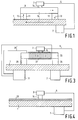
- Fig. 1 is a sectional view of a portion 1 of an outer wall of a body of a vehicle, for example a car. At least the wall portion 1 shown (in this case a part of the roof of the car) is made of a ferromagnetic material, for example steel.
- the magnetic field sensor 3 which is arranged outside the vehicle in the present example can also be arranged inside the vehicle, for example between the roof of the car and its lining.
- the wall portion 1 shown is included in a magnetic circuit which, in the present embodiment, also comprises a yoke 9 which consists of a number of stacked plates of a soft magnetic material (for example, silicon iron) and two or more permanent magnets 11, for example of ferroxdure.
- the magnets 11 connect the wall portion 1 to the yoke 9 and are polarized so that the magnetic fields generated in the wall portion and the yoke by the magnets intensify one another.
- the direction of the magnetization thus generated in the various parts of the magnetic circuit is denoted by arrows 13.
- the magnetic sensor 3 is mounted over the yoke 9 by way of a support 14, so that it is rigidly connected to the wall portion 1.
- the senor 3 can also be accommodated in a recess (not shown) provided in the yoke 9 for this purpose.
- the yoke 9 may comprise a number of stacked, rectangular frames of a soft magnetic material, for example a permanent magnet 11 being arranged at each corner of the yoke.
- the magnetic circuit and the sensor 3 can be provided on top of the roof ( i.e. outside the vehicle), but it is alternatively possible to mount the magnetic circuit and/or the sensor on the lower side of the roof ( i.e. within the vehicle).
- Fig. 2 shows the effect of the described construction on the horizontal component B xm of the magnetic induction, measured 1 cm above the roof of a car and induced by an external DC magnetic field B ex .
- the curve 15 represents the variation of B xm after the roof has been exposed to an external field B ex without special steps being taken
- the curve 17 represents the same variation after installation of a magnetic circuit as shown in Fig. 1.
- the magnetic circuit consisted of four NdFeB magnets 11 of 13 x 7 x 3 mm3, magnetized along the short axis, and a soft magnetic yoke 9 consisting of two plates (120 x 120 x 0.5 mm3) and six frames (120 x 120 x 0.5 mm3 with an opening of 80 x 80 mm2).
- Fig. 2A shows the effect of external fields of between 0 and 5 x 10 ⁇ 4 T and Fig. 2B shows, at an increased scale, a part 19 of Fig. 2A with external fields of between 0 and 2 x 10 ⁇ 4 T.
- the Figures also show a horizontal line 21 which corresponds to a B xm of 0.025 x 10 ⁇ 4 T, i.e. approximately 10% of the value of the terrestrial magnetic field.
- the Figures show that a external field of 5 x 10 ⁇ 4 T causes a disturbance of 1.25 x 10 ⁇ 4 if no steps are taken. After installation of the magnetic circuit, the disturbance amounts to only 0.255 x 10 ⁇ 4 T, implying an improvement by a factor 5.
- the installation of the magnetic circuit causes stray fields of approximately from 3 x 10 ⁇ 5 to 5 x 10 ⁇ 5 T within the car, directly below the roof of the car. These fields are so small that there is no risk of small iron objects in the car being attracted by the roof.
- the sensitivity of the sensor 3 to the terrestrial field is reduced by the introduction of the magnetic circuit.
- rotation of the vehicle through 180° leads to a shift of 2 x 5 x 10 ⁇ 5 T in the measured field strength.
- this signal has decreased to 1 x 10 ⁇ 5 T.
- the net improvement of the sensitivity of the sensor signal thus amounts to a factor 2.
- the decrease of the sensitivity to the terrestrial magnetic field is due to the capture of a part of the flux by the yoke 9. This effect occurs whenever the sensor 3 is situated in the direct vicinity of a non-saturated soft magnetic yoke.
- the described method thus enables an improvement of the stability of the compass signal by approximately a factor 2.
- the described configuration is simple, tugged and compact (the thickness is approximately 1 cm).
- the permanent magnetization of a part of the roof could be a drawback.
- Fig. 3 shows an embodiment of a device comprising a magnetic circuit enabling a substantially smaller magnetization of the roof.
- the magnetic circuit comprises an electromagnet whereby the relevant wall portion 1 can be brought into a predetermined magnetic state.
- the circuit comprises a yoke which has an approximately U-shaped cross-section and which is made of a soft magnetic material, said yoke comprising a base portion 23 which may be constructed in the same way as the yoke 9 shown in Fig. 1 and also comprises a number (preferably two) of limbs 25, the free ends of which face the wall portion 1.
- the base portion 23 is surrounded by an electric coil 27 in the form of a solenoid, thus forming an electromagnet.
- the coil 27 is connected, via two connection wires 29, to a power supply apparatus 31 capable of supplying the coil with a variable current.
- the dimensions of the base portion 23 are, for example 120 x 185 x 1 mm3 and the coil 27 comprises, for example 4000 turns per meter.
- the power supply apparatus 31 supplies a current of 1 A
- the coil thus induces a magnetic field of 4000 x 1/2 A/m in the yoke 25, 27.
- the field strength required to saturate the metal of the portion 1 of the car roof amounted to approximately 6000 A/m.
- the magnetization M of the wall portion 1 is of the order of magnitude of the terrestrial field and hence the magnetic induction caused by the wall portion at the area of the sensor 3 is also of the order of magnitude of the terrestrial field.
- the magnetization of the wall portion 1 amounts to -M r and M r , respectively, and the induction caused thereby at the area of the sensor amounts to -B r and B r , respectively.
- the step 2 need not necessarily be preceded by the step 1.
- the state of remanence can in principle be reached from any arbitrary initial state. Executing the step 1 in advance, however, offers the advantage that the initial state is thus suitably defined.
- the magnetic induction B a caused by the terrestrial field at the area of the sensor 3 is then measured in the remanent state of the material of the wall portion 1, it being evident that correction must be made for the induction B r or -B r caused by the remanent magnetization.
- This value can subsequently be used as a correction quantity for the measurements undertaken after execution of only step 2 or 3.
- B r does not change between measurements. Because B r may vary over prolonged periods of time, for example due to temperature fluctuations or ageing of the material, B r should be determined again at regular intervals. However, this is not objectionable because this determination is particularly simple.
- no current flows through a coil 27 and the yoke 23, 25 forms a short-circuit for the magnetization M r so that the value of B r is limited. Because the yoke cannot be saturated in this state, in the present embodiment it also absorbs a part of the terrestrial field, resulting in a reduction of the useful signal produced by the sensor.
- the magnetic induction was measured at 1 cm above the car roof after each of the above steps. Subsequently, an interference field of 5 x 10 ⁇ 4 T was applied, after which the measuring series was repeated. During the repetition of the measuring series, each time first a measurement was performed with the vehicle in a first position (position 1), followed by a measurement after rotation of the vehicle through 180°. In order to examine the reproducibility, two measurements were performed in each point with remanent magnetization. The result is given in the below Table, the measuring results being stated in units of 10 ⁇ 7 T.
- the variation of the measured value of B a caused by the rotation of the vehicle through 180° (the difference between B a in the position 1 and B a in the position 2) amounts to 56.7 x 10 ⁇ 7 T before application of the interference field and to 58.8 x 10 ⁇ 7 T after application of the interference field.
- the difference caused by the interference fields therefore, is smaller than 2 x 10 ⁇ 7 T, which is approximately a factor 600 better than if no precautions are taken.
- the difference is of the same order of magnitude as the reproducibility of the measurements.
- the measured value is approximately a factor 4 to 5 smaller than the actual value of the inductance caused by the terrestrial field (2.7 x 10 ⁇ 5 T), so the sensitivity is reduced by a factor of from 4 to 5 by provision of the yoke 23, 25.
- the net increase of the stability is thus a factor 80 to 100.
- the sensitivity could be further increased by providing a flux concentrator (not shown), but that would also cause a stronger coupling in of the stray field of the roof.
- An embodiment in which the yoke 23, 25 is made of a ferromagnetic material (for example, sheet steel) offers the advantage that the disturbing induction due to the magnetization of the roof could be substantially eliminated.
- the measured value of B a is then only a factor of from 1 to 2 smaller than the actual value.
- the net increase of the stability is then approximately a factor 400.
- Fig. 4 shows an embodiment of the device in accordance with the invention in which the wall portion 1 situated in the direct vicinity of the sensor 3 is magnetically stabilized because it contains a hard magnetic material.
- a hard magnetic material for example, ferroxdure
- the wall portion 1 then being made of a customary sheet steel covered with a layer of lacquer 33 containing grains of a hard magnetic material.
- the lacquer contains uniformly distributed grains of ferroxdure of a size of the order of magnitude of 1 mm.
- the hard magnetic material has the property that its magnetization state is difficult to change by the normally occurring external disturbing magnetic fields, so that the disturbing magnetic induction caused by the relevant wall portion 1 at the area of the sensor is substantially constant.
Landscapes
- Engineering & Computer Science (AREA)
- Radar, Positioning & Navigation (AREA)
- Remote Sensing (AREA)
- Physics & Mathematics (AREA)
- General Physics & Mathematics (AREA)
- Electromagnetism (AREA)
- Measuring Magnetic Variables (AREA)
Applications Claiming Priority (2)
| Application Number | Priority Date | Filing Date | Title |
|---|---|---|---|
| EP92201018 | 1992-04-09 | ||
| EP92201018 | 1992-04-09 |
Publications (2)
| Publication Number | Publication Date |
|---|---|
| EP0565177A1 true EP0565177A1 (fr) | 1993-10-13 |
| EP0565177B1 EP0565177B1 (fr) | 1996-09-18 |
Family
ID=8210540
Family Applications (1)
| Application Number | Title | Priority Date | Filing Date |
|---|---|---|---|
| EP93200933A Expired - Lifetime EP0565177B1 (fr) | 1992-04-09 | 1993-04-01 | Dispositif pour déterminer l'orientation d'un véhicule |
Country Status (4)
| Country | Link |
|---|---|
| US (1) | US5481808A (fr) |
| EP (1) | EP0565177B1 (fr) |
| JP (1) | JPH0666566A (fr) |
| DE (1) | DE69304768T2 (fr) |
Families Citing this family (2)
| Publication number | Priority date | Publication date | Assignee | Title |
|---|---|---|---|---|
| US7969150B2 (en) * | 2004-12-13 | 2011-06-28 | Baker Hughes Incorporated | Demagnetizer to eliminate residual magnetization of wellbore wall produced by nuclear magnetic resonance logs |
| US7913756B2 (en) * | 2004-12-13 | 2011-03-29 | Baker Hughes Incorporated | Method and apparatus for demagnetizing a borehole |
Citations (3)
| Publication number | Priority date | Publication date | Assignee | Title |
|---|---|---|---|---|
| EP0067337A1 (fr) * | 1981-06-11 | 1982-12-22 | Siemens Aktiengesellschaft | Arrangement d'une sonde de champ magnétique sur un véhicule |
| US4523386A (en) * | 1980-12-26 | 1985-06-18 | Nippon Soken, Inc. | Heading detecting apparatus |
| DE3421249A1 (de) * | 1984-06-07 | 1985-12-12 | Siemens AG, 1000 Berlin und 8000 München | Anordnung einer magnetfeldsonde in einem fahrzeug |
Family Cites Families (7)
| Publication number | Priority date | Publication date | Assignee | Title |
|---|---|---|---|---|
| US4060845A (en) * | 1976-03-25 | 1977-11-29 | The Arnold Engineering Company | Portable demagnetizer |
| US4358886A (en) * | 1979-06-21 | 1982-11-16 | Nippon Soken, Inc. | Method of mounting an azimuth indicator in an automobile |
| JPS5814056B2 (ja) * | 1980-05-28 | 1983-03-17 | 株式会社日本自動車部品総合研究所 | 車両用消磁装置 |
| JPS56167308A (en) * | 1980-05-28 | 1981-12-23 | Nippon Soken Inc | Magnetic eraser for vehicle |
| JPS5784310A (en) * | 1980-11-13 | 1982-05-26 | Alps Electric Co Ltd | Direction sensing means |
| DE3123180A1 (de) * | 1981-06-11 | 1983-01-05 | Siemens AG, 1000 Berlin und 8000 München | Korrekturverfahren und -einrichtung fuer eine magnetfeldsonde |
| JPH03179212A (ja) * | 1989-12-07 | 1991-08-05 | Pioneer Electron Corp | 地磁気センサ |
-
1993
- 1993-04-01 EP EP93200933A patent/EP0565177B1/fr not_active Expired - Lifetime
- 1993-04-01 DE DE69304768T patent/DE69304768T2/de not_active Expired - Fee Related
- 1993-04-07 JP JP5080686A patent/JPH0666566A/ja active Pending
-
1995
- 1995-04-10 US US08/422,664 patent/US5481808A/en not_active Expired - Fee Related
Patent Citations (3)
| Publication number | Priority date | Publication date | Assignee | Title |
|---|---|---|---|---|
| US4523386A (en) * | 1980-12-26 | 1985-06-18 | Nippon Soken, Inc. | Heading detecting apparatus |
| EP0067337A1 (fr) * | 1981-06-11 | 1982-12-22 | Siemens Aktiengesellschaft | Arrangement d'une sonde de champ magnétique sur un véhicule |
| DE3421249A1 (de) * | 1984-06-07 | 1985-12-12 | Siemens AG, 1000 Berlin und 8000 München | Anordnung einer magnetfeldsonde in einem fahrzeug |
Non-Patent Citations (3)
| Title |
|---|
| PATENT ABSTRACTS OF JAPAN vol. 15, no. 430 (P-1270)31 October 1991 & JP-A-31 79 212 ( PIONEER ELECTRON CORP ) 5 August 1991 * |
| PATENT ABSTRACTS OF JAPAN vol. 5, no. 175 (P-88)11 November 1981 & JP-A-56 103 311 ( NISSAN MOTOR CO LTD ) 18 August 1981 * |
| PATENT ABSTRACTS OF JAPAN vol. 7, no. 113 (P-197)18 May 1983 & JP-A-58 033 116 ( HONDA GIKEN KOGYO KK ) 26 February 1983 * |
Also Published As
| Publication number | Publication date |
|---|---|
| DE69304768T2 (de) | 1997-03-27 |
| EP0565177B1 (fr) | 1996-09-18 |
| JPH0666566A (ja) | 1994-03-08 |
| US5481808A (en) | 1996-01-09 |
| DE69304768D1 (de) | 1996-10-24 |
Similar Documents
| Publication | Publication Date | Title |
|---|---|---|
| Calhoun | Magnetic and electric properties of magnetite at low temperatures | |
| US5066891A (en) | Magnetic field cancellation circuit | |
| US6201386B1 (en) | Method for demagnetizing and measuring remanence and coercivity characteristics of a magnetic sample | |
| DE3266336D1 (en) | Method and circuit arrangement for measuring a magnetic field, especially the terrestrial magnetic field | |
| JPH08179020A (ja) | 磁気補正回路及びそれを用いた画像表示装置 | |
| JPS6217844B2 (fr) | ||
| EP0565177B1 (fr) | Dispositif pour déterminer l'orientation d'un véhicule | |
| US4388666A (en) | Demagnetizer for use in vehicles | |
| US3931618A (en) | Housing structure and magnetic biasing for bubble memories | |
| JPS62139304A (ja) | 磁界均一性のよい磁気回路 | |
| JPS56147086A (en) | Flux gate type magnetic sensor | |
| JPS6153843B2 (fr) | ||
| SU1647791A1 (ru) | Электромагнитный вибратор | |
| Nakata et al. | Effects of geomagnetism and residual magnetism on single sheet testers for amorphous magnetic material | |
| SU1218356A1 (ru) | Приемное устройство вибрационного магнитометра | |
| JPS6325907A (ja) | Mri磁場発生装置 | |
| US11887763B2 (en) | Degaussing a magnetized structure | |
| SU1511655A1 (ru) | Способ формировани пол ризующего магнитного пол в радиоспектроскопической аппаратуре | |
| SU1081498A1 (ru) | Стабилизатор пол электромагнита | |
| JPS62105069A (ja) | 磁界検出装置 | |
| SU1280553A1 (ru) | Способ контрол магнитных свойств посто нных магнитов | |
| Sasaki | On the field errors at low magnetic field of the AC magnets for a synchrotron | |
| JPH01206605A (ja) | 磁界発生装置 | |
| SU995126A1 (ru) | Магнитный экран | |
| JPH07324934A (ja) | 地磁気方位センサ |
Legal Events
| Date | Code | Title | Description |
|---|---|---|---|
| PUAI | Public reference made under article 153(3) epc to a published international application that has entered the european phase |
Free format text: ORIGINAL CODE: 0009012 |
|
| AK | Designated contracting states |
Kind code of ref document: A1 Designated state(s): DE FR GB IT SE |
|
| K1C3 | Correction of patent application (complete document) published |
Effective date: 19931013 |
|
| 17P | Request for examination filed |
Effective date: 19940406 |
|
| 17Q | First examination report despatched |
Effective date: 19951026 |
|
| GRAH | Despatch of communication of intention to grant a patent |
Free format text: ORIGINAL CODE: EPIDOS IGRA |
|
| GRAH | Despatch of communication of intention to grant a patent |
Free format text: ORIGINAL CODE: EPIDOS IGRA |
|
| GRAA | (expected) grant |
Free format text: ORIGINAL CODE: 0009210 |
|
| AK | Designated contracting states |
Kind code of ref document: B1 Designated state(s): DE FR GB IT SE |
|
| REF | Corresponds to: |
Ref document number: 69304768 Country of ref document: DE Date of ref document: 19961024 |
|
| ITF | It: translation for a ep patent filed | ||
| ET | Fr: translation filed | ||
| PLBE | No opposition filed within time limit |
Free format text: ORIGINAL CODE: 0009261 |
|
| STAA | Information on the status of an ep patent application or granted ep patent |
Free format text: STATUS: NO OPPOSITION FILED WITHIN TIME LIMIT |
|
| 26N | No opposition filed | ||
| REG | Reference to a national code |
Ref country code: FR Ref legal event code: CD |
|
| PGFP | Annual fee paid to national office [announced via postgrant information from national office to epo] |
Ref country code: SE Payment date: 20010425 Year of fee payment: 9 |
|
| REG | Reference to a national code |
Ref country code: GB Ref legal event code: IF02 |
|
| PG25 | Lapsed in a contracting state [announced via postgrant information from national office to epo] |
Ref country code: SE Free format text: LAPSE BECAUSE OF NON-PAYMENT OF DUE FEES Effective date: 20020402 |
|
| EUG | Se: european patent has lapsed |
Ref document number: 93200933.5 |
|
| REG | Reference to a national code |
Ref country code: GB Ref legal event code: 746 Effective date: 20021025 |
|
| REG | Reference to a national code |
Ref country code: FR Ref legal event code: D6 |
|
| PGFP | Annual fee paid to national office [announced via postgrant information from national office to epo] |
Ref country code: FR Payment date: 20030424 Year of fee payment: 11 |
|
| PGFP | Annual fee paid to national office [announced via postgrant information from national office to epo] |
Ref country code: GB Payment date: 20030430 Year of fee payment: 11 |
|
| PGFP | Annual fee paid to national office [announced via postgrant information from national office to epo] |
Ref country code: DE Payment date: 20030616 Year of fee payment: 11 |
|
| PG25 | Lapsed in a contracting state [announced via postgrant information from national office to epo] |
Ref country code: GB Free format text: LAPSE BECAUSE OF NON-PAYMENT OF DUE FEES Effective date: 20040401 |
|
| PG25 | Lapsed in a contracting state [announced via postgrant information from national office to epo] |
Ref country code: DE Free format text: LAPSE BECAUSE OF NON-PAYMENT OF DUE FEES Effective date: 20041103 |
|
| GBPC | Gb: european patent ceased through non-payment of renewal fee | ||
| PG25 | Lapsed in a contracting state [announced via postgrant information from national office to epo] |
Ref country code: FR Free format text: LAPSE BECAUSE OF NON-PAYMENT OF DUE FEES Effective date: 20041231 |
|
| REG | Reference to a national code |
Ref country code: FR Ref legal event code: ST |
|
| PG25 | Lapsed in a contracting state [announced via postgrant information from national office to epo] |
Ref country code: IT Free format text: LAPSE BECAUSE OF NON-PAYMENT OF DUE FEES Effective date: 20050401 |