EP0565200A1 - Tunnelier avec bouclier cylindrique - Google Patents
Tunnelier avec bouclier cylindrique Download PDFInfo
- Publication number
- EP0565200A1 EP0565200A1 EP93201018A EP93201018A EP0565200A1 EP 0565200 A1 EP0565200 A1 EP 0565200A1 EP 93201018 A EP93201018 A EP 93201018A EP 93201018 A EP93201018 A EP 93201018A EP 0565200 A1 EP0565200 A1 EP 0565200A1
- Authority
- EP
- European Patent Office
- Prior art keywords
- ring
- cylindrical
- tunnelling machine
- shield
- adjusting
- Prior art date
- Legal status (The legal status is an assumption and is not a legal conclusion. Google has not performed a legal analysis and makes no representation as to the accuracy of the status listed.)
- Withdrawn
Links
- 230000001154 acute effect Effects 0.000 claims abstract description 4
- 239000000314 lubricant Substances 0.000 claims description 5
- 238000009412 basement excavation Methods 0.000 description 6
- 238000009415 formwork Methods 0.000 description 4
- 239000000463 material Substances 0.000 description 3
- 238000002347 injection Methods 0.000 description 2
- 239000007924 injection Substances 0.000 description 2
- 230000005641 tunneling Effects 0.000 description 2
- 239000004568 cement Substances 0.000 description 1
- 239000000470 constituent Substances 0.000 description 1
- 230000008878 coupling Effects 0.000 description 1
- 238000010168 coupling process Methods 0.000 description 1
- 238000005859 coupling reaction Methods 0.000 description 1
- 239000012530 fluid Substances 0.000 description 1
- 230000001788 irregular Effects 0.000 description 1
- 238000005065 mining Methods 0.000 description 1
- 239000004576 sand Substances 0.000 description 1
- 238000007789 sealing Methods 0.000 description 1
- XLYOFNOQVPJJNP-UHFFFAOYSA-N water Substances O XLYOFNOQVPJJNP-UHFFFAOYSA-N 0.000 description 1
Images


Classifications
-
- E—FIXED CONSTRUCTIONS
- E21—EARTH OR ROCK DRILLING; MINING
- E21D—SHAFTS; TUNNELS; GALLERIES; LARGE UNDERGROUND CHAMBERS
- E21D9/00—Tunnels or galleries, with or without linings; Methods or apparatus for making thereof; Layout of tunnels or galleries
- E21D9/06—Making by using a driving shield, i.e. advanced by pushing means bearing against the already placed lining
- E21D9/0621—Shield advancing devices
Definitions
- the invention relates to a tunnelling machine with a cylindrical shield.
- an excavating head is fitted in front of the shield, said excavating head in a known embodiment (DE-A-2,164,816) being adjustable relative to the shield, so that the direction of excavation can be adjusted.
- This combination of two different functions - determining the direction of excavation to be followed by the position of the excavating head, on the one hand, and the excavation itself, on the other - leads to a situation in which irregular resistances experienced by the excavating head have a direct influence on the direction of excavation, so that it becomes particularly difficult to maintain a predetermined direction of excavation in certain types of ground.
- the object of the invention is to overcome this drawback, and to provide a tunnelling machine by means of which it is ensured in a particularly simple way that a predetermined direction of excavation is in fact followed accurately, any marked-out curved route also has precisely the predetermined radius of curvature, and this marked-out plan can have any desired course in three-dimensional terms.
- the shield is divided into a number of cylindrical segments interconnected in the lengthwise direction and having radial end edges, at least one adjusting ring which is rotatable about the axis of the segment being fitted between two adjacent end edges, while the two radial ring surfaces of said ring include an acute angle.
- the angle between the respective segments can be determined accurately in three dimensions, sothat the shape of the shield itself can be controlled - of course within practical limits - in three dimensions, it is ensured that the tunnel route accurately follows a predetermined marked-out plan. There are no problems when this tunnel route is a sineous one, even in three dimensions.
- Another advantage is that the entire tunneling machine tends to follow any curvature in its path initiated by the shield.
- DE-A-2545041 describes a tunneling machine comprising a shield which is connected to a following tunneltube by means of a connecting tube, devided into two parts; the deviding plane of this connecting tube includes an acute angle with the plane normal to the axis of both the shield and the tunneltube.
- Each halve of the connecting tube can be rotated around its respective axis. In this way it is possible to adjust the position of the entire shield with respect to the tunneltube which follows it. This arrangement does not result in the unique adjustability and flexibility in following a predetermined path which is obtained by the arrangement according to the invention.
- Each adjusting ring preferably co-operates with an identical second adjusting ring which is also rotatable about the axis of the segment. An increased adjustability is obtained thereby.
- a groove which is concentric with the axis of the ring is formed in each ring, said groove being provided with internal toothing which meshes with a pinion driven by an adjusting motor.
- the ring(s) is (are) enclosed in an annular chamber formed by, on the one hand, the radially inward directed end edges - lying opposite each other at a distance from each other - of two adjacent segments and, on the other, coaxial, cylindrical end edges which connect thereto at the top and bottom edge thereof, respectively, and which each by means of a cylindrical elastic connecting piece bear a cylindrical seal which rests against the top and bottom edge of the ring(s), respectively, said chamber being filled under pressure with a lubricant.
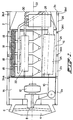
- the tunnelling machine of which Figure 1 shows the front part, is of the so-called shield type with the shield 2, and has at the front end, shown on the left in Figure 1, a diagrammatically shown excavating head 4 with excavating cutters 6 and a collection unit 8 for the excavated material, which is removed by means of the conveyor belt 10.
- the excavating head is accommodated together with the diagrammatically shown drive 12 in the front compartment 14 of the tunnelling machine. Since these parts do not constitute a subject of the invention and their actual embodiment depends entirely on the circumstances in which the tunnelling machine is to be used, they will not be discussed in any further detail.
- a compact concrete batching and mixing plant Situated in the compartment 16, following the compartment 14, is a compact concrete batching and mixing plant with four hoppers 18, containing the constituent materials for the concrete to be formed, a centrifuge 20, and a mixer 22 for these materials.
- Water, sand, cement and gravel are supplied by means of a suitable system of ducts and pipes.
- the still fluid concrete is supplied by means of the system of plunger pumps 28 through pipes 30 to a number of injection pipes opening out at the rear end of the machine, which is not shown. This is not essential for the invention either; other layouts and embodiments are possible.
- Formwork is erected in the usual way inside the shield 2, comprising segments (not shown) which define the inner periphery of the tunnel to be formed, and which are combined to form a closed formwork cylinder by means of a suitable handling and erection system which is known per se. These parts are situated at the rear end of the machine.
- the tunnelling machine is operated in the usual way: when the shield advances in the direction of the arrow 50, which can take place in any suitable manner, but for which the so-called self-advancing blade system (developed by Westfalia-Luenen) will preferably be used, the space around the formwork is filled up with concrete coming out of the injection pipes. This concrete, hardening round the formwork, eventually forms the outside tunnel wall.
- the so-called self-advancing blade system developed by Westfalia-Luenen
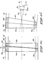
- the shield being sub-divided into a number of segments 2a...2e etc., the mutual angular position of which can be adjusted within certain limits.
- This adjustability is achieved by means of at least one adjusting ring fitted between two segments connecting to each other, and preferably through the use of two such adjusting rings.
- a pair of adjusting rings 34a is fitted between the segments 2a, 2b, an adjusting ring is fitted at 34b between the segments 2b and 2c, a pair of adjusting rings 34c between the segments 2c and 2d, a pair of adjusting rings 34d between the segments 2d and 2e, etc.
- the way in which such a pair of adjusting rings, indicated by 34 in Figures 2 to 5, operates can be seen in particular from Figures 2a and 2b.
- Each pair of adjusting rings in the preferred embodiment comprises two adjusting rings 36a, 36b. They are identical and each have a radial end surface 38a, 38b, respectively, situated at right angles to the axis 32, and a second end surface 40a, 40b, respectively, which includes a small angle ⁇ with said surfaces 38a, 38b.
- the widest part 36a' of adjusting ring 36 rests against the narrowest part 36b' of adjusting ring 36b, so that the shield wall segments connected to the segments 36a, 36b, respectively, for example the segments 2a and 2b, are accurately in line with each other.
- Figure 4 shows how this can be achieved.
- the figure shows the segment wall parts 2a, 2b with the annular end edges 42a, 42b positioned at right angles thereto. Confined between them are the rings 36a, 36b, respectively, each of which has the configuration shown in Figures 2a and 2b. These rings rest with their side faces 38a, 38b against the flat, radial side walls of the edges 42a, 42b and are enclosed at the top and bottom edges, respectively, by a locking ring 44, 46, respectively, which locking rings are connected by means of vulcanised-on sealing rings 48a, 48b and 50a, 50b, respectively, to the end rings 52a, 52b and 54a, 54b, respectively, supported by the segment 2a, 2b, respectively.
- Each of the adjusting rings 36a, 36b bears a ring-shaped inner toothing 56a, 56b, in which meshes a pinion 58a, 58b fitted on the shaft of an adjusting motor 60a and 60b. These motors are supported by the respective segment end edges 42a, 42b.
- adjusting rings 36a, 36b can be moved into any desired angular position relative to each other by rotation of the pinions 58a, 58b.
- the two adjusting rings 36a, 36b are accommodated in a closed chamber which is filled under pressure with a suitable lubricant through a conduct 49, connected to a schematically shown source of pressurised lubricant 51.
- Figure 5 shows a somewhat modified embodiment.
- This figure shows two segments 60a, 60b of the shield of a tunnelling machine around which the drive blades of the so-called self-advancing blade system, as developed by Westfalia Luenen, are fitted, and of which two are shown, indicated by 62, 64, respectively.
- the space accommodating the rings is filled under pressure with a suitable lubricant, in a manner similar to the one described above and not illustrated in any further detail.
Landscapes
- Engineering & Computer Science (AREA)
- Mining & Mineral Resources (AREA)
- Environmental & Geological Engineering (AREA)
- Life Sciences & Earth Sciences (AREA)
- General Life Sciences & Earth Sciences (AREA)
- Geochemistry & Mineralogy (AREA)
- Geology (AREA)
- Lining And Supports For Tunnels (AREA)
- Excavating Of Shafts Or Tunnels (AREA)
Applications Claiming Priority (2)
| Application Number | Priority Date | Filing Date | Title |
|---|---|---|---|
| NL9200673A NL9200673A (nl) | 1992-04-10 | 1992-04-10 | Tunnelgraafmachine met cylindrisch schild. |
| NL9200673 | 1992-04-10 |
Publications (1)
| Publication Number | Publication Date |
|---|---|
| EP0565200A1 true EP0565200A1 (fr) | 1993-10-13 |
Family
ID=19860685
Family Applications (1)
| Application Number | Title | Priority Date | Filing Date |
|---|---|---|---|
| EP93201018A Withdrawn EP0565200A1 (fr) | 1992-04-10 | 1993-04-06 | Tunnelier avec bouclier cylindrique |
Country Status (3)
| Country | Link |
|---|---|
| EP (1) | EP0565200A1 (fr) |
| JP (1) | JPH0650094A (fr) |
| NL (1) | NL9200673A (fr) |
Cited By (1)
| Publication number | Priority date | Publication date | Assignee | Title |
|---|---|---|---|---|
| CN107100645A (zh) * | 2017-06-30 | 2017-08-29 | 中交二公局第四工程有限公司 | 基于bim技术的盾构隧道曲线区段管片预拼装选型设计方法 |
Families Citing this family (3)
| Publication number | Priority date | Publication date | Assignee | Title |
|---|---|---|---|---|
| JP2015040372A (ja) * | 2013-08-20 | 2015-03-02 | 鉄建建設株式会社 | シールドによる場所打ちライニングコンクリート工法用内型枠 |
| CN112412494B (zh) * | 2020-12-07 | 2025-04-04 | 北京市市政工程设计研究总院有限公司 | 一种带牛腿连接基座预制的管片拼装的衬砌圆环及其拼装方法 |
| CN113482644B (zh) * | 2021-03-09 | 2022-04-19 | 中铁工程装备集团有限公司 | 一种双结构tbm |
Citations (1)
| Publication number | Priority date | Publication date | Assignee | Title |
|---|---|---|---|---|
| DE2545041A1 (de) * | 1975-10-08 | 1977-04-21 | Peiner Masch Schrauben | Vorrichtung zum lenken eines tunnelrohres |
-
1992
- 1992-04-10 NL NL9200673A patent/NL9200673A/nl not_active Application Discontinuation
-
1993
- 1993-04-06 EP EP93201018A patent/EP0565200A1/fr not_active Withdrawn
- 1993-04-08 JP JP5106061A patent/JPH0650094A/ja active Pending
Patent Citations (1)
| Publication number | Priority date | Publication date | Assignee | Title |
|---|---|---|---|---|
| DE2545041A1 (de) * | 1975-10-08 | 1977-04-21 | Peiner Masch Schrauben | Vorrichtung zum lenken eines tunnelrohres |
Cited By (2)
| Publication number | Priority date | Publication date | Assignee | Title |
|---|---|---|---|---|
| CN107100645A (zh) * | 2017-06-30 | 2017-08-29 | 中交二公局第四工程有限公司 | 基于bim技术的盾构隧道曲线区段管片预拼装选型设计方法 |
| CN107100645B (zh) * | 2017-06-30 | 2019-07-23 | 中交二公局第四工程有限公司 | 基于bim技术的盾构隧道曲线区段管片预拼装选型设计方法 |
Also Published As
| Publication number | Publication date |
|---|---|
| JPH0650094A (ja) | 1994-02-22 |
| NL9200673A (nl) | 1993-11-01 |
Similar Documents
| Publication | Publication Date | Title |
|---|---|---|
| EP2119868A1 (fr) | Machine excavatrice a bouclier | |
| EP0122540B1 (fr) | Procédé et installation de poussée pour bouclier de tunnel | |
| EP0574187B1 (fr) | Machine d'avancement de tunnel à bouclier | |
| EP0342246B1 (fr) | Méthode de rénovation d'une tuyauterie existante et dispositif pour cela | |
| EP0565200A1 (fr) | Tunnelier avec bouclier cylindrique | |
| EP0348118B1 (fr) | Procédé et dispositif pour forer un trou dans le sol | |
| GB1570329A (en) | Method and apparatus for excavating horizontal tunnels | |
| JPH0465956B2 (fr) | ||
| KR900008912B1 (ko) | 시일드식 터널 굴삭기 | |
| JP2001115798A (ja) | 三重筒式トンネル埋戻し装置 | |
| JP7194002B2 (ja) | 掘削機 | |
| JPH03290591A (ja) | 既設管路の更新装置 | |
| JPH0213599Y2 (fr) | ||
| JPH1122379A (ja) | 既設管の布設替え工法及び掘進機 | |
| JPS6172196A (ja) | シ−ルド工法による横坑掘削方法およびそのシ−ルド掘進機 | |
| KR102293628B1 (ko) | 커터헤드부의 개구율을 조절하여 굴착토의 유입량의 조절이 가능한 기계식 굴착기 | |
| JPH1061383A (ja) | シールド掘進機 | |
| JPS6214236Y2 (fr) | ||
| JPS5915188A (ja) | 中折れ式シ−ルド掘進機 | |
| KR930008639B1 (ko) | 기설관로의 갱신방법 및 장치 | |
| JP2003148088A (ja) | 掘進機 | |
| JPS63189595A (ja) | 既設管路の更新装置 | |
| JPH0414557Y2 (fr) | ||
| JPH03166492A (ja) | シールド工法 | |
| JPH0791941B2 (ja) | シールドトンネルの地中接合工法及びそのシールド掘進機 |
Legal Events
| Date | Code | Title | Description |
|---|---|---|---|
| PUAI | Public reference made under article 153(3) epc to a published international application that has entered the european phase |
Free format text: ORIGINAL CODE: 0009012 |
|
| AK | Designated contracting states |
Kind code of ref document: A1 Designated state(s): AT CH DE FR IT LI NL |
|
| 17P | Request for examination filed |
Effective date: 19930816 |
|
| 17Q | First examination report despatched |
Effective date: 19941223 |
|
| STAA | Information on the status of an ep patent application or granted ep patent |
Free format text: STATUS: THE APPLICATION IS DEEMED TO BE WITHDRAWN |
|
| 18D | Application deemed to be withdrawn |
Effective date: 19950503 |