EP0565689B1 - Agencement pour l'alimentation en carburant d'un moteur a combustion interne - Google Patents
Agencement pour l'alimentation en carburant d'un moteur a combustion interne Download PDFInfo
- Publication number
- EP0565689B1 EP0565689B1 EP92922849A EP92922849A EP0565689B1 EP 0565689 B1 EP0565689 B1 EP 0565689B1 EP 92922849 A EP92922849 A EP 92922849A EP 92922849 A EP92922849 A EP 92922849A EP 0565689 B1 EP0565689 B1 EP 0565689B1
- Authority
- EP
- European Patent Office
- Prior art keywords
- fuel
- line
- internal combustion
- combustion engine
- pressure regulator
- Prior art date
- Legal status (The legal status is an assumption and is not a legal conclusion. Google has not performed a legal analysis and makes no representation as to the accuracy of the status listed.)
- Expired - Lifetime
Links
- 239000000446 fuel Substances 0.000 title claims abstract description 50
- 238000002485 combustion reaction Methods 0.000 title claims abstract description 25
- 239000002828 fuel tank Substances 0.000 claims abstract description 21
- 238000002347 injection Methods 0.000 claims abstract description 13
- 239000007924 injection Substances 0.000 claims abstract description 13
- 230000001105 regulatory effect Effects 0.000 abstract 1
- 230000002000 scavenging effect Effects 0.000 abstract 1
- 238000010438 heat treatment Methods 0.000 description 5
- 238000010586 diagram Methods 0.000 description 2
- 238000011161 development Methods 0.000 description 1
- 230000018109 developmental process Effects 0.000 description 1
- 230000000694 effects Effects 0.000 description 1
- 230000007613 environmental effect Effects 0.000 description 1
- 238000011010 flushing procedure Methods 0.000 description 1
- 238000000034 method Methods 0.000 description 1
- 238000010943 off-gassing Methods 0.000 description 1
- 239000000243 solution Substances 0.000 description 1
- 238000010792 warming Methods 0.000 description 1
- 239000002918 waste heat Substances 0.000 description 1
Images
Classifications
-
- B—PERFORMING OPERATIONS; TRANSPORTING
- B60—VEHICLES IN GENERAL
- B60K—ARRANGEMENT OR MOUNTING OF PROPULSION UNITS OR OF TRANSMISSIONS IN VEHICLES; ARRANGEMENT OR MOUNTING OF PLURAL DIVERSE PRIME-MOVERS IN VEHICLES; AUXILIARY DRIVES FOR VEHICLES; INSTRUMENTATION OR DASHBOARDS FOR VEHICLES; ARRANGEMENTS IN CONNECTION WITH COOLING, AIR INTAKE, GAS EXHAUST OR FUEL SUPPLY OF PROPULSION UNITS IN VEHICLES
- B60K15/00—Arrangement in connection with fuel supply of combustion engines or other fuel consuming energy converters, e.g. fuel cells; Mounting or construction of fuel tanks
- B60K15/03—Fuel tanks
- B60K15/077—Fuel tanks with means modifying or controlling distribution or motion of fuel, e.g. to prevent noise, surge, splash or fuel starvation
-
- Y—GENERAL TAGGING OF NEW TECHNOLOGICAL DEVELOPMENTS; GENERAL TAGGING OF CROSS-SECTIONAL TECHNOLOGIES SPANNING OVER SEVERAL SECTIONS OF THE IPC; TECHNICAL SUBJECTS COVERED BY FORMER USPC CROSS-REFERENCE ART COLLECTIONS [XRACs] AND DIGESTS
- Y02—TECHNOLOGIES OR APPLICATIONS FOR MITIGATION OR ADAPTATION AGAINST CLIMATE CHANGE
- Y02T—CLIMATE CHANGE MITIGATION TECHNOLOGIES RELATED TO TRANSPORTATION
- Y02T10/00—Road transport of goods or passengers
- Y02T10/10—Internal combustion engine [ICE] based vehicles
- Y02T10/12—Improving ICE efficiencies
Definitions
- the invention relates to an arrangement for supplying fuel to an internal combustion engine arranged in an engine compartment, starting from a fuel tank located outside the engine compartment, a fuel feed line having a pump leading to the internal combustion engine and a pressure regulator being provided which has a branch line branching off the feed line connects the return line leading to the fuel tank in order to set a desired fuel pressure in the supply line.
- Such an arrangement for supplying fuel to an internal combustion engine is known, for example, from DE 39 14 939 A1.
- the pressure regulator is arranged near the internal combustion engine or near the fuel injection valves which are attached to the internal combustion engine suction system and branch off from the end of the supply line on the engine compartment side.
- the pump delivery rate is dimensioned so that a sufficient amount of fuel is available in all possible engine operating points and in particular also in the operating point of the maximum nominal output. At part-load operating points, a relatively large, excess fuel volume flow is therefore available, which returns to the fuel tank via the return line.
- the pressure regulator adjusts the volume flow entering the return line so that a defined fuel pressure is present in the supply line. This excess fuel pressure can be defined either in relation to the ambient pressure or in relation to the pressure conditions in the intake system.
- the object of the invention is therefore to demonstrate measures by means of which heating of the fuel volume in the fuel tank, as a result of the engine compartment waste heat, is largely prevented.
- the excess fuel flow conveyed by the pump no longer passes through the engine compartment, but is already branched off from the supply line outside the same. Any heating of the fuel volume returning to the fuel tank by the internal combustion engine is thus largely excluded.
- the effect according to the invention can be further increased if the branch line and the pressure regulator are arranged near the fuel tank.
- the arrangement according to the invention is preferably located in a motor vehicle, the internal combustion engine and the engine compartment being located in the front of the vehicle and the fuel tank in the rear of the vehicle. If the pressure regulator and the branch line are then also arranged in the rear of the vehicle, heating from environmental influences is almost impossible.
- the pressure regulator can alternatively be connectable to the end of the flow line on the engine compartment side.
- This connection between the pressure regulator and the engine compartment end of the supply line is then briefly established when the internal combustion engine is started, in order to rinse the engine compartment end of the supply line, from which the fuel injection nozzles branch off, and thus to remove possible fuel vapor bubbles.
- the branch line branching off from the supply line outside the engine compartment and in particular near the fuel tank is in turn connected to the pressure regulator, and the connection between the pressure regulator and the end of the supply line on the engine compartment side tion interrupted.
- a simple changeover valve can be provided.
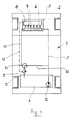
- a motor vehicle 1 denotes a motor vehicle, the bow of which has a closed engine compartment 2, in which an internal combustion engine 3 driving motor vehicle 1 is arranged.
- a fuel tank 4 is arranged in the rear of the motor vehicle 1.
- the internal combustion engine 3 is supplied with fuel from this fuel tank 4 via a feed line 5.
- the internal combustion engine 3 is provided with a fuel injection bar 6, which is supplied with fuel via the feed line 5 and thus virtually forms the end of the feed line 5 on the engine compartment side.
- the injection valves 7 assigned to the individual cylinders of the internal combustion engine branch off from this injection rail 6 and open into the intake system 8 of the internal combustion engine 3.
- a defined fuel pressure must be present in the injection bar 6.
- This fuel pressure is set by means of a pressure regulator 9, which connects the feed line 5 to a return line 11 which opens without pressure in the fuel tank 4 via a branch line 10.
- An excess fuel flow conveyed by the fuel pump 12 is thus simply branched off in order to produce the desired pressure level in the injection bar 6. Since in the present case this desired pressure level is defined as the differential pressure in relation to the pressure conditions prevailing in the suction system 8, the pressure regulator 9 is additionally acted upon by the pressure prevailing in the suction system 8 via a pressure line 13.
- the branch line 10, which leads from the feed line 5 to the pressure regulator 9 via a changeover valve 14, which will be explained later, and via this as well as via the return line 11 to the fuel tank 4, is, like the pressure regulator 9, outside the engine compartment 2 and in particular in the vicinity of the fuel tank 4 arranged.
- the injection strip 6 can be connected to the pressure regulator 9 as an alternative to the branch line 10 with its end facing away from the flow line 5 and thus also the end of the flow line 5 on the engine compartment side. This alternative connection is made by means of the changeover valve 14.
Landscapes
- Engineering & Computer Science (AREA)
- Life Sciences & Earth Sciences (AREA)
- Sustainable Development (AREA)
- Sustainable Energy (AREA)
- Chemical & Material Sciences (AREA)
- Combustion & Propulsion (AREA)
- Transportation (AREA)
- Mechanical Engineering (AREA)
- Fuel-Injection Apparatus (AREA)
Abstract
Claims (3)
Applications Claiming Priority (3)
| Application Number | Priority Date | Filing Date | Title |
|---|---|---|---|
| DE4136833A DE4136833A1 (de) | 1991-11-08 | 1991-11-08 | Anordnung zur kraftstoff-versorgung einer brennkraftmaschine |
| DE4136833 | 1991-11-08 | ||
| PCT/EP1992/002498 WO1993009000A1 (fr) | 1991-11-08 | 1992-10-30 | Agencement pour l'alimentation en carburant d'un moteur a combustion interne |
Publications (3)
| Publication Number | Publication Date |
|---|---|
| EP0565689A1 EP0565689A1 (fr) | 1993-10-20 |
| EP0565689B1 true EP0565689B1 (fr) | 1995-05-17 |
| EP0565689B2 EP0565689B2 (fr) | 1998-05-13 |
Family
ID=6444388
Family Applications (1)
| Application Number | Title | Priority Date | Filing Date |
|---|---|---|---|
| EP92922849A Expired - Lifetime EP0565689B2 (fr) | 1991-11-08 | 1992-10-30 | Agencement pour l'alimentation en carburant d'un moteur a combustion interne |
Country Status (4)
| Country | Link |
|---|---|
| US (1) | US5373829A (fr) |
| EP (1) | EP0565689B2 (fr) |
| DE (2) | DE4136833A1 (fr) |
| WO (1) | WO1993009000A1 (fr) |
Families Citing this family (20)
| Publication number | Priority date | Publication date | Assignee | Title |
|---|---|---|---|---|
| US5598817A (en) * | 1993-09-10 | 1997-02-04 | Mitsubishi Jidosha Kogyo Kabushiki Kaisha | Fuel feeding system for internal combustion engine |
| FR2711734B1 (fr) * | 1993-10-29 | 1995-11-24 | Renault | Procédé de commande d'une pompe à carburant de moteur à combustion interne. |
| DE4344775A1 (de) * | 1993-12-28 | 1995-06-29 | Technoflow Tube Systems Gmbh | Kraftstoff-Versorgungssystem für ein Kraftfahrzeug mit Ottomotor |
| JP3156218B2 (ja) * | 1994-04-22 | 2001-04-16 | 三菱電機株式会社 | 燃料供給装置及び調圧装置 |
| US5558068A (en) * | 1994-05-31 | 1996-09-24 | Zexel Corporation | Solenoid valve unit for fuel injection apparatus |
| US5699772A (en) * | 1995-01-17 | 1997-12-23 | Nippondenso Co., Ltd. | Fuel supply system for engines with fuel pressure control |
| DE19510497A1 (de) * | 1995-03-23 | 1996-09-26 | Pierburg Gmbh | Brennstoffversorgungssystem für Brennkraftmaschinen |
| IT1281303B1 (it) * | 1995-03-28 | 1998-02-17 | Elasis Sistema Ricerca Fiat | Dispositivo di regolazione della pressione di alimentazione di un fluido in un accumulatore di fluido in pressione, ad esempio per |
| US5623907A (en) * | 1995-06-09 | 1997-04-29 | Walbro Corporation | Liquid propane fuel delivery system |
| JPH08338335A (ja) * | 1995-06-09 | 1996-12-24 | Nippondenso Co Ltd | 内燃機関の燃料供給装置 |
| DE19540892A1 (de) * | 1995-11-02 | 1997-05-07 | Bayerische Motoren Werke Ag | Kraftstoffanlage |
| US5765537A (en) * | 1997-01-17 | 1998-06-16 | Caterpillar Inc. | Fuel recirculation system |
| DE19822164A1 (de) * | 1998-05-16 | 1999-11-18 | Audi Ag | Kraftstoffversorgungssystem für eine Brennkraftmaschine |
| DE19903273A1 (de) * | 1999-01-28 | 2000-08-10 | Bosch Gmbh Robert | Kraftstoffversorgungssystem für eine Brennkraftmaschine insbesondere eines Kraftfahrzeugs |
| FR2791093B1 (fr) * | 1999-03-18 | 2001-05-04 | Inst Francais Du Petrole | Systeme d'alimentation en carburant liquide sous pression d'un moteur a combustion interne |
| US7318414B2 (en) * | 2002-05-10 | 2008-01-15 | Tmc Company | Constant-speed multi-pressure fuel injection system for improved dynamic range in internal combustion engine |
| JP4207834B2 (ja) * | 2003-06-27 | 2009-01-14 | 株式会社デンソー | 蓄圧式燃料噴射システム |
| JP4670450B2 (ja) * | 2005-04-15 | 2011-04-13 | トヨタ自動車株式会社 | 内燃機関の燃料供給装置 |
| US7779818B2 (en) * | 2007-07-12 | 2010-08-24 | Caterpillar Inc. | System and method for priming a fluid system |
| US8622047B2 (en) * | 2010-09-24 | 2014-01-07 | Denso Corporation | Cleaning a pressure control function valve |
Family Cites Families (16)
| Publication number | Priority date | Publication date | Assignee | Title |
|---|---|---|---|---|
| DE2137832C2 (de) * | 1970-08-10 | 1986-04-17 | Nippondenso Co., Ltd., Kariya, Aichi | Einrichtung zum Einspritzen von Kraftstoff in eine Brennkraftmaschine |
| DE2130174C3 (de) * | 1971-06-18 | 1979-04-26 | Daimler-Benz Ag, 7000 Stuttgart | Elektronisch gesteuerte Benzin-Einspritzeinrichtung für Brennkraftmaschinen |
| NL153975B (nl) * | 1974-02-05 | 1977-07-15 | Doornes Bedrijfswagen Fab | Brandstofverbruikmeetinrichting voor een verbrandingsmotor. |
| DE2549104A1 (de) * | 1975-11-03 | 1977-05-05 | Volkswagenwerk Ag | Kraftstoff-foerdereinrichtung |
| DE2841557A1 (de) * | 1978-09-23 | 1980-04-03 | Daimler Benz Ag | Kraftstoffsystem fuer ein kraftfahrzeug |
| JPS6115248Y2 (fr) * | 1981-01-12 | 1986-05-12 | ||
| US4440138A (en) * | 1982-02-16 | 1984-04-03 | Stanadyne, Inc. | Diesel engine fuel system |
| JPS59150967A (ja) * | 1983-02-18 | 1984-08-29 | Automob Antipollut & Saf Res Center | 燃料ポンプ装置 |
| DE3720067A1 (de) * | 1986-07-05 | 1988-01-07 | Bosch Gmbh Robert | Kraftstoffeinspritzvorrichtung fuer brennkraftmaschinen |
| DE3710807A1 (de) * | 1987-03-31 | 1988-10-13 | Daimler Benz Ag | Niederdruckkraftstoffkreislauf mit kraftstoffvorwaermung fuer eine luftverdichtende einspritzbrennkraftmaschine |
| US4784104A (en) * | 1987-06-18 | 1988-11-15 | Brunswick Corporation | Fuel line with integral co-axial return line |
| CH674243A5 (fr) * | 1987-07-08 | 1990-05-15 | Dereco Dieselmotoren Forschung | |
| DE3914939A1 (de) * | 1989-05-06 | 1990-11-08 | Bayerische Motoren Werke Ag | Niederdruck-brennstoff-einspritzanlage |
| JPH0374569A (ja) * | 1989-08-15 | 1991-03-29 | Fuji Heavy Ind Ltd | ガソリンエンジンの燃料噴射制御装置 |
| US5148792A (en) * | 1992-01-03 | 1992-09-22 | Walbro Corporation | Pressure-responsive fuel delivery system |
| US5207203A (en) * | 1992-03-23 | 1993-05-04 | General Motors Corporation | Fuel system |
-
1991
- 1991-11-08 DE DE4136833A patent/DE4136833A1/de not_active Withdrawn
-
1992
- 1992-10-30 EP EP92922849A patent/EP0565689B2/fr not_active Expired - Lifetime
- 1992-10-30 WO PCT/EP1992/002498 patent/WO1993009000A1/fr not_active Ceased
- 1992-10-30 US US08/084,231 patent/US5373829A/en not_active Expired - Fee Related
- 1992-10-30 DE DE59202253T patent/DE59202253D1/de not_active Expired - Fee Related
Also Published As
| Publication number | Publication date |
|---|---|
| WO1993009000A1 (fr) | 1993-05-13 |
| DE4136833A1 (de) | 1993-05-13 |
| EP0565689B2 (fr) | 1998-05-13 |
| EP0565689A1 (fr) | 1993-10-20 |
| DE59202253D1 (de) | 1995-06-22 |
| US5373829A (en) | 1994-12-20 |
Similar Documents
| Publication | Publication Date | Title |
|---|---|---|
| EP0565689B1 (fr) | Agencement pour l'alimentation en carburant d'un moteur a combustion interne | |
| EP1012470B1 (fr) | Systeme d'alimentation en carburant | |
| DE102004009792B3 (de) | Kraftstoffzuführeinrichtung zur Versorgung der Injektoren an Brennräumen einer Brennkraftmaschine mit Kraftstoff | |
| DE10061987B4 (de) | Verfahren und Vorrichtung zum Kühlen einer Kraftstoffeinspritzanlage | |
| EP1126157A2 (fr) | Dispositif d'alimentation en carburant pour un moteur à combustion d'un véhicule | |
| DE102014222463A1 (de) | Vorrichtung zur Wassereinspritzung und Verfahren zum Betrieb einer solchen | |
| EP1348072B1 (fr) | Procede, programme informatique et appareil de commande et/ou de reglage permettant d'exploiter un moteur a combustion interne et moteur a combustion interne | |
| DE19936287A1 (de) | Bedarfssteuerung für ein Kraftstoffördermodul mit variablem Systemdruck | |
| EP1254311B1 (fr) | Systeme d'alimentation en carburant pour moteurs a combustion interne, permettant une meilleur remplissage de la conduite de carburant | |
| DE3825470C2 (fr) | ||
| EP1124054B1 (fr) | Système d'alimentation en carburant pour un moteur à combustion | |
| DE102009028739A1 (de) | Schnellstart eines Common Rail-Systems | |
| DE3914939C2 (fr) | ||
| DE10127516A1 (de) | Verfahren, Computerprogramm und Steuer- und/oder Regelgerät zum Betreiben einer Brennkraftmaschine sowie Kraftstoffsystem für eine Brennkraftmaschine | |
| DE10137869A1 (de) | Einspritzanlage und Verfahren zu deren Betrieb | |
| EP1124055B1 (fr) | Système d'alimentation en carburant pour moteur à combustion | |
| DE102005028931B4 (de) | Kraftstoffversorgungssystem für einen Verbrennungsmotor | |
| DE69914069T2 (de) | Vorrichtung und verfahren zur rückführung des kraftstoffes für ein direkteinspritzsystem | |
| DE3909750C2 (fr) | ||
| EP0864458A1 (fr) | Dispositif d'alimentation de carburant pour un monteur à combustion | |
| DE19933569B4 (de) | Einspritzsystem für eine Brennkraftmaschine | |
| EP1554486B1 (fr) | Ensemble pompe | |
| EP1826396B1 (fr) | Système d'Injection Rampe Commune | |
| DE10026373A1 (de) | Hochdruck-Kraftstoffeinspritzanlage für eine Brennkraftmaschine | |
| DE69903191T2 (de) | Kraftstoffzufuhreinrichtung einer brennkraftmaschine mit direkter einspritzung |
Legal Events
| Date | Code | Title | Description |
|---|---|---|---|
| PUAI | Public reference made under article 153(3) epc to a published international application that has entered the european phase |
Free format text: ORIGINAL CODE: 0009012 |
|
| 17P | Request for examination filed |
Effective date: 19930702 |
|
| AK | Designated contracting states |
Kind code of ref document: A1 Designated state(s): DE FR GB IT |
|
| 17Q | First examination report despatched |
Effective date: 19941103 |
|
| GRAA | (expected) grant |
Free format text: ORIGINAL CODE: 0009210 |
|
| AK | Designated contracting states |
Kind code of ref document: B1 Designated state(s): DE FR GB IT |
|
| ET | Fr: translation filed | ||
| REF | Corresponds to: |
Ref document number: 59202253 Country of ref document: DE Date of ref document: 19950622 |
|
| GBT | Gb: translation of ep patent filed (gb section 77(6)(a)/1977) |
Effective date: 19950620 |
|
| ITF | It: translation for a ep patent filed | ||
| PLBI | Opposition filed |
Free format text: ORIGINAL CODE: 0009260 |
|
| PLAV | Examination of admissibility of opposition |
Free format text: ORIGINAL CODE: EPIDOS OPEX |
|
| PLBI | Opposition filed |
Free format text: ORIGINAL CODE: 0009260 |
|
| PLAV | Examination of admissibility of opposition |
Free format text: ORIGINAL CODE: EPIDOS OPEX |
|
| 26 | Opposition filed |
Opponent name: PIERBURG GMBH Effective date: 19960208 |
|
| 26 | Opposition filed |
Opponent name: MERCEDES-BENZ AG Effective date: 19960216 Opponent name: PIERBURG GMBH Effective date: 19960208 |
|
| PLBF | Reply of patent proprietor to notice(s) of opposition |
Free format text: ORIGINAL CODE: EPIDOS OBSO |
|
| PLBF | Reply of patent proprietor to notice(s) of opposition |
Free format text: ORIGINAL CODE: EPIDOS OBSO |
|
| PLAW | Interlocutory decision in opposition |
Free format text: ORIGINAL CODE: EPIDOS IDOP |
|
| PLAW | Interlocutory decision in opposition |
Free format text: ORIGINAL CODE: EPIDOS IDOP |
|
| PUAH | Patent maintained in amended form |
Free format text: ORIGINAL CODE: 0009272 |
|
| STAA | Information on the status of an ep patent application or granted ep patent |
Free format text: STATUS: PATENT MAINTAINED AS AMENDED |
|
| 27A | Patent maintained in amended form |
Effective date: 19980513 |
|
| AK | Designated contracting states |
Kind code of ref document: B2 Designated state(s): DE FR GB IT |
|
| ET3 | Fr: translation filed ** decision concerning opposition | ||
| GBTA | Gb: translation of amended ep patent filed (gb section 77(6)(b)/1977) | ||
| ITF | It: translation for a ep patent filed | ||
| REG | Reference to a national code |
Ref country code: GB Ref legal event code: IF02 |
|
| PGFP | Annual fee paid to national office [announced via postgrant information from national office to epo] |
Ref country code: GB Payment date: 20031028 Year of fee payment: 12 |
|
| PGFP | Annual fee paid to national office [announced via postgrant information from national office to epo] |
Ref country code: FR Payment date: 20031030 Year of fee payment: 12 |
|
| PGFP | Annual fee paid to national office [announced via postgrant information from national office to epo] |
Ref country code: DE Payment date: 20031120 Year of fee payment: 12 |
|
| PG25 | Lapsed in a contracting state [announced via postgrant information from national office to epo] |
Ref country code: GB Free format text: LAPSE BECAUSE OF NON-PAYMENT OF DUE FEES Effective date: 20041030 |
|
| PG25 | Lapsed in a contracting state [announced via postgrant information from national office to epo] |
Ref country code: DE Free format text: LAPSE BECAUSE OF NON-PAYMENT OF DUE FEES Effective date: 20050503 |
|
| GBPC | Gb: european patent ceased through non-payment of renewal fee |
Effective date: 20041030 |
|
| PG25 | Lapsed in a contracting state [announced via postgrant information from national office to epo] |
Ref country code: FR Free format text: LAPSE BECAUSE OF NON-PAYMENT OF DUE FEES Effective date: 20050630 |
|
| REG | Reference to a national code |
Ref country code: FR Ref legal event code: ST |
|
| PG25 | Lapsed in a contracting state [announced via postgrant information from national office to epo] |
Ref country code: IT Free format text: LAPSE BECAUSE OF NON-PAYMENT OF DUE FEES;WARNING: LAPSES OF ITALIAN PATENTS WITH EFFECTIVE DATE BEFORE 2007 MAY HAVE OCCURRED AT ANY TIME BEFORE 2007. THE CORRECT EFFECTIVE DATE MAY BE DIFFERENT FROM THE ONE RECORDED. Effective date: 20051030 |