EP0565737A1 - Verfahren zur korrektur des kopfendes des werkzeuges - Google Patents
Verfahren zur korrektur des kopfendes des werkzeuges Download PDFInfo
- Publication number
- EP0565737A1 EP0565737A1 EP93908769A EP93908769A EP0565737A1 EP 0565737 A1 EP0565737 A1 EP 0565737A1 EP 93908769 A EP93908769 A EP 93908769A EP 93908769 A EP93908769 A EP 93908769A EP 0565737 A1 EP0565737 A1 EP 0565737A1
- Authority
- EP
- European Patent Office
- Prior art keywords
- center point
- tool center
- tool
- robot
- moving target
- Prior art date
- Legal status (The legal status is an assumption and is not a legal conclusion. Google has not performed a legal analysis and makes no representation as to the accuracy of the status listed.)
- Granted
Links
Images



Classifications
-
- G—PHYSICS
- G05—CONTROLLING; REGULATING
- G05B—CONTROL OR REGULATING SYSTEMS IN GENERAL; FUNCTIONAL ELEMENTS OF SUCH SYSTEMS; MONITORING OR TESTING ARRANGEMENTS FOR SUCH SYSTEMS OR ELEMENTS
- G05B19/00—Program-control systems
- G05B19/02—Program-control systems electric
- G05B19/18—Numerical control [NC], i.e. automatically operating machines, in particular machine tools, e.g. in a manufacturing environment, so as to execute positioning, movement or co-ordinated operations by means of program data in numerical form
- G05B19/404—Numerical control [NC], i.e. automatically operating machines, in particular machine tools, e.g. in a manufacturing environment, so as to execute positioning, movement or co-ordinated operations by means of program data in numerical form characterised by control arrangements for compensation, e.g. for backlash, overshoot, tool offset, tool wear, temperature, machine construction errors, load, inertia
-
- B—PERFORMING OPERATIONS; TRANSPORTING
- B25—HAND TOOLS; PORTABLE POWER-DRIVEN TOOLS; MANIPULATORS
- B25J—MANIPULATORS; CHAMBERS PROVIDED WITH MANIPULATION DEVICES
- B25J9/00—Program-controlled manipulators
- B25J9/10—Program-controlled manipulators characterised by positioning means for manipulator elements
-
- G—PHYSICS
- G05—CONTROLLING; REGULATING
- G05B—CONTROL OR REGULATING SYSTEMS IN GENERAL; FUNCTIONAL ELEMENTS OF SUCH SYSTEMS; MONITORING OR TESTING ARRANGEMENTS FOR SUCH SYSTEMS OR ELEMENTS
- G05B2219/00—Program-control systems
- G05B2219/30—Nc systems
- G05B2219/37—Measurements
- G05B2219/37251—Selfcorrecting, counter for tool life adapts correction
-
- G—PHYSICS
- G05—CONTROLLING; REGULATING
- G05B—CONTROL OR REGULATING SYSTEMS IN GENERAL; FUNCTIONAL ELEMENTS OF SUCH SYSTEMS; MONITORING OR TESTING ARRANGEMENTS FOR SUCH SYSTEMS OR ELEMENTS
- G05B2219/00—Program-control systems
- G05B2219/30—Nc systems
- G05B2219/45—Nc applications
- G05B2219/45083—Manipulators, robot
Definitions
- the present invention relates to a method of correcting a tool center point, which corrects a position of the tool center point of a robot, and in particular, to a method which corrects a change amount of the tool center point caused by consumption, wear or the like, thus accurately controlling the position of the tool center point.
- Tools attached to a robot are consumed or worn by different using modes.
- a welding gun is used as a tool, but the gun tip is consumed in accordance with the number of robot's works.
- a position of a TCP Tool Center Point
- a spring mechanism for correcting the change is ordinarily located in a mechanical section of the welding gun.
- a grinder is used as a tool, but the grinder attached to the robot is worn in accordance with the working time when grinding the workpiece surface.
- a spring mechanism for pressing the grinder against the workpiece must be attached to the grinder likewise.
- an object of the present invention is to provide a method of correcting a position of a tool center point, which is capable of designing lightweight and inexpensive tools such as a welding gun, grinder or the like.
- Another object of the present invention is to provide a method of correcting a position of a tool center point, which is capable of readily handling and controlling robot manipulation programs.
- a method of correcting a position of a tool center point which corrects the position of the tool center point of the robot, comprising the steps of: previously storing in memory the relationship between the working time of the robot and a change amount of the tool center point of the robot, accumulating the working time, determining the change amount of the tool center point corresponding to the accumulated working time, when the tool center point is aligned with a moving target position, correcting the moving target position of the tool center point on the basis of the determined change amount of the tool center point, and moving the tool center point to the corrected moving target position.
- Data indicating the relationship between the working time and the change amount of the tool center point of the robot are previously stored in memory. Further, the time when the robot is working is accumulated. Then, when the tool center point is moved to the moving target position, the change amount of the tool center point corresponding to the accumulated working time is determined on the basis of the data stored in the memory. The moving target position of the tool center point is corrected on the basis of the determined changed amount of the tool center point, thus the tool center point being moved to the corrected moving target position. Accordingly, even though the position of the tool center point is changed by the consumption, wear or the like, the position of the tool center point is corrected in accordance with the change amount. This allows the accurate performance of the spot welding or grinding relative to the moving target position on the workpiece surface. As a consequence, it is unnecessary to attach the spring mechanism required in prior art to the robot. In addition, it is possible to make a plurality of robot manipulation programs into a single program.
- Fig. 2 is a view schematically showing a configuration of a robot system for carrying out a method of correcting a position of a tool center point.
- a robot 20 is a multiple joint spot welding robot, and a welding gun 22 for the spot welding is attached to a flange 25 of the distal end of an arm 21 as a tool.
- a robot control device 10 mainly comprises a micro processor which will be described later, and drives respective servo motor of the robot 20, thus controlling the operations of the robot 20 and welding gun 22 pursuant to preset operating programs.
- the spot welding is carried out by using the welding gun 22 which includes two gun tips 23A and 23B.
- the spot welding is performed relative to a workpiece interposed between the gun tips 23A and 23B.
- the lower gun tip 23B is positioned, while the upper gun tip 23A is moved in the up-and-down direction, thus the spot welding being performed.
- the distal end portion of the gun tip 23A is consumed in accordance with the working time of the robot, so that the position of distal end portion of gun tip 23A deviates from the preset position.
- TCP23C positional change (caused by consumption) of the distal end portion (referred to as "TCP23C" later) of the gun tip 23A.
- the position of the TCP23C is represented on a hand coordinate system with the surface of the flange 25 being a base.
- the method of correcting the position of the TCP23C will be explained on the basis of the flowchart later.
- Fig. 1 is a flowchart for carrying out the method of correcting a tool center point according to the present invention; in the figure, a numeral next to S denotes a step number.
- the change amount of the TCP23C is determined on the basis of data previously stored in the memory, but it may be a structure so that the TCP23C is directly measured by using external sensors such as a camera or the like, and the change amount of the TCP23C is determined on the basis of the measurement results.
- Fig. 4 is a block diagram schematically showing the robot control device 10.
- the robot control device 10 includes a processor board 11 comprising a processor 11a, ROM 11b and RAM 11c.
- the processor 11a controls the entirety of robot control device pursuant to system programs stored in the ROM 11b.
- the RAM 11c stores various data such as operating programs for the robot 20 or programs for carrying out the present invention. Part of the RAM 11c is constituted as a nonvolatile memory in which the operating programs is stored.
- the processor board 11 is connected to a bus 19.
- a digital servo control circuit 12 is connected to the bus 19 and drives servo motors 51, 52, 53, 54, 55 and 56 are driven in accordance with a command from the processor board 11 through a servo amplifier 13. These servo motors 51 to 56 are included in the robot 20, and operate respective axes of the robot 20.
- a serial port 14, digital I/O 15, analog I/O 17 and mass memory 18 are connected to the bus 19, respectively.
- a teaching operation panel 57 with a display, other RS232C equipment 58 and CRT 16a are connected to the serial port 14, respectively, and an operation panel 16b is connected to the digital I/O 15.
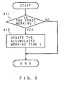
- the mass memory 18 stores the initial position data of the TCP23C previously taught, data indicating the relationship between the working time and change amount of the TCP23C, accumulated working time t or the like.
- the present invention may be applied in robots performing other operations; for example, a robot for grinding, likewise.
- a grinder is used as a tool, but it is unnecessary to locate a spring mechanism for pressing the grinder against the workpiece, so that a lightweight and inexpensive grinder can be provided.
- the respective joint angle values is used as positional command data to the robot, but other positional command data may be applied in the present invention likewise.
- positional command data to the robot
- positional command data may also be applied in the present invention likewise.
- a method of correcting a position of a tool center point comprising the steps of: previously storing in memory data indicating the relationship between the working time of robot and the consumption of tool center point, determining a positional change of TCP corresponding to the accumulated working time on the basis of the data; and correcting the position in accordance with the change, thus setting a moving target point for the TCP. Accordingly, it is possible to accurately perform the robot manipulations such as spot welding, grinding or the like relative to the moving target point on the workpiece. This allows the elimination of a spring mechanism required in the prior art, and the provision of lightweight and inexpensive tools. In addition, it is possible to make a plurality of robot manipulation programs which are set in accordance with the change amount of the tool center point into a single program, so that the robot manipulation programs can readily be handled and controlled.
Landscapes
- Engineering & Computer Science (AREA)
- Human Computer Interaction (AREA)
- Manufacturing & Machinery (AREA)
- Physics & Mathematics (AREA)
- General Physics & Mathematics (AREA)
- Automation & Control Theory (AREA)
- Robotics (AREA)
- Mechanical Engineering (AREA)
- Manipulator (AREA)
- Numerical Control (AREA)
Applications Claiming Priority (3)
| Application Number | Priority Date | Filing Date | Title |
|---|---|---|---|
| JP26768391A JP3230826B2 (ja) | 1991-10-16 | 1991-10-16 | スポット溶接ガンの位置補正方法及びロボット溶接装置 |
| JP267683/91 | 1991-10-16 | ||
| PCT/JP1992/001328 WO1993007998A1 (fr) | 1991-10-16 | 1992-10-12 | Procede pour corriger la position de l'extremite avant d'un outil |
Publications (3)
| Publication Number | Publication Date |
|---|---|
| EP0565737A1 true EP0565737A1 (de) | 1993-10-20 |
| EP0565737A4 EP0565737A4 (en) | 1994-07-27 |
| EP0565737B1 EP0565737B1 (de) | 1997-03-19 |
Family
ID=17448084
Family Applications (1)
| Application Number | Title | Priority Date | Filing Date |
|---|---|---|---|
| EP93908769A Expired - Lifetime EP0565737B1 (de) | 1991-10-16 | 1992-10-12 | Verfahren zur korrektur des kopfendes des werkzeuges |
Country Status (6)
| Country | Link |
|---|---|
| US (1) | US5451850A (de) |
| EP (1) | EP0565737B1 (de) |
| JP (1) | JP3230826B2 (de) |
| KR (1) | KR960010445B1 (de) |
| DE (1) | DE69218401T2 (de) |
| WO (1) | WO1993007998A1 (de) |
Cited By (3)
| Publication number | Priority date | Publication date | Assignee | Title |
|---|---|---|---|---|
| EP0810497A4 (de) * | 1995-12-19 | 1998-05-20 | Hitachi Construction Machinery | Verfahren zur korrektur des ausgangsignals eines steuergerätes, steuergerät und steuergerät für hydraulikpumpe |
| US6101456A (en) * | 1995-03-07 | 2000-08-08 | Hitachi Construction Machinery Co., Ltd. | Output correcting method in control system, control system, and hydraulic pump control system |
| WO2011030138A2 (en) | 2009-09-08 | 2011-03-17 | Movirtu Limited | Method and system to enable multiple virtual numbers across different mobile networks |
Families Citing this family (11)
| Publication number | Priority date | Publication date | Assignee | Title |
|---|---|---|---|---|
| JP3665353B2 (ja) * | 1993-09-14 | 2005-06-29 | ファナック株式会社 | ロボットの教示位置データの3次元位置補正量取得方法及びロボットシステム |
| JP3681431B2 (ja) * | 1995-02-21 | 2005-08-10 | ファナック株式会社 | 直交座標系上で柔らかさが調節可能なサーボ系 |
| JPH0970780A (ja) * | 1995-09-06 | 1997-03-18 | Fanuc Ltd | ロボットのツール形状補正方式 |
| US6044310A (en) * | 1997-10-21 | 2000-03-28 | Douglass; Thomas E. | System for automatic alignment of a workpiece |
| JP2006099260A (ja) * | 2004-09-28 | 2006-04-13 | Fanuc Ltd | ロボットプログラム作成装置 |
| JP2006236031A (ja) * | 2005-02-25 | 2006-09-07 | Seiko Epson Corp | ロボット軌跡制御方法及び装置並びにロボット軌跡制御方法のプログラム |
| CN101361030B (zh) * | 2006-01-14 | 2012-06-06 | 通快机床两合公司 | 轴控制方法 |
| JP2016185572A (ja) * | 2015-03-27 | 2016-10-27 | セイコーエプソン株式会社 | ロボット、ロボット制御装置およびロボットシステム |
| DE112021001155T5 (de) | 2020-02-20 | 2022-12-01 | Fanuc Corporation | Numerische Steuervorrichtung für Werkzeugmaschine |
| CN111906766B (zh) * | 2020-09-15 | 2022-01-07 | 珠海格力智能装备有限公司 | 工件定位方法及装置、机器人设备、计算机可读存储介质 |
| DE112022000273T5 (de) * | 2021-01-29 | 2023-12-21 | Fanuc Corporation | Programmevaluationsvorrichtung und teaching-vorrichtung |
Family Cites Families (21)
| Publication number | Priority date | Publication date | Assignee | Title |
|---|---|---|---|---|
| US3860779A (en) * | 1972-03-22 | 1975-01-14 | Charmilles Sa Ateliers | Method and apparatus for positioning an electrode-tool relative to a workpiece in electrical discharge machining |
| JPS52116983A (en) * | 1976-03-25 | 1977-09-30 | Koyo Seiko Co Ltd | Automatic method for correcting position of bite with respect to wear of bite |
| JPS5412085A (en) * | 1977-06-29 | 1979-01-29 | Oki Electric Ind Co Ltd | Timely controlled data presenting method in nc |
| JPS5544681A (en) * | 1978-09-27 | 1980-03-29 | Fanuc Ltd | Tool correction system |
| JPS59201740A (ja) * | 1983-04-25 | 1984-11-15 | Toyoda Mach Works Ltd | 自動工具交換方法 |
| JPS59212909A (ja) * | 1983-05-17 | 1984-12-01 | Toyoda Mach Works Ltd | 工具寸法補正制御装置 |
| JPS6020893A (ja) * | 1983-07-15 | 1985-02-02 | 新明和工業株式会社 | 作業工具装置 |
| JPS6129908A (ja) * | 1984-07-20 | 1986-02-12 | Matsushita Electric Ind Co Ltd | 数値制御工作機械の工具位置補正方法 |
| JPS6190205A (ja) * | 1984-10-09 | 1986-05-08 | Komatsu Ltd | ロボツトの絶対位置決め誤差補償方法 |
| JPS61233806A (ja) * | 1985-04-08 | 1986-10-18 | Mitsubishi Electric Corp | 産業用ロボツト |
| JPS6242941U (de) * | 1985-09-04 | 1987-03-14 | ||
| JPS62206606A (ja) * | 1986-03-07 | 1987-09-11 | Nec Corp | 工具摩耗量の補正方法 |
| JPH08384B2 (ja) * | 1987-09-16 | 1996-01-10 | ファナック株式会社 | ツール先端点の自動設定方式 |
| US4986724A (en) * | 1987-11-10 | 1991-01-22 | Cincinnati Milacron Inc. | System for compensated motion of coupled robot axes |
| JPH01132343A (ja) * | 1987-11-16 | 1989-05-24 | Daiichi Kasei:Kk | 畜肉・水産加工品 |
| CS270004B1 (en) * | 1987-12-12 | 1990-06-13 | Valenta Jiri | Method of cutting process trajectory adaptive control and device for realization of this method |
| JPH01132343U (de) * | 1988-03-01 | 1989-09-08 | ||
| US4969108A (en) * | 1988-04-08 | 1990-11-06 | Cincinnati Milacron Inc. | Vision seam tracking method and apparatus for a manipulator |
| JPH0373253A (ja) * | 1989-04-11 | 1991-03-28 | Nippondenso Co Ltd | 工具摩耗補正方法 |
| US4990743A (en) * | 1989-05-10 | 1991-02-05 | Daihen Corporation | Control method for tracing a weld line in a welding apparatus |
| JPH033760A (ja) * | 1989-05-30 | 1991-01-09 | Fanuc Ltd | デジタイジング制御装置 |
-
1991
- 1991-10-16 JP JP26768391A patent/JP3230826B2/ja not_active Expired - Fee Related
-
1992
- 1992-10-12 WO PCT/JP1992/001328 patent/WO1993007998A1/ja not_active Ceased
- 1992-10-12 US US08/064,160 patent/US5451850A/en not_active Expired - Lifetime
- 1992-10-12 EP EP93908769A patent/EP0565737B1/de not_active Expired - Lifetime
- 1992-10-12 KR KR1019930701801A patent/KR960010445B1/ko not_active Expired - Fee Related
- 1992-10-12 DE DE69218401T patent/DE69218401T2/de not_active Expired - Fee Related
Cited By (3)
| Publication number | Priority date | Publication date | Assignee | Title |
|---|---|---|---|---|
| US6101456A (en) * | 1995-03-07 | 2000-08-08 | Hitachi Construction Machinery Co., Ltd. | Output correcting method in control system, control system, and hydraulic pump control system |
| EP0810497A4 (de) * | 1995-12-19 | 1998-05-20 | Hitachi Construction Machinery | Verfahren zur korrektur des ausgangsignals eines steuergerätes, steuergerät und steuergerät für hydraulikpumpe |
| WO2011030138A2 (en) | 2009-09-08 | 2011-03-17 | Movirtu Limited | Method and system to enable multiple virtual numbers across different mobile networks |
Also Published As
| Publication number | Publication date |
|---|---|
| EP0565737B1 (de) | 1997-03-19 |
| JPH05108123A (ja) | 1993-04-30 |
| JP3230826B2 (ja) | 2001-11-19 |
| KR960010445B1 (ko) | 1996-08-01 |
| DE69218401T2 (de) | 1997-06-26 |
| US5451850A (en) | 1995-09-19 |
| DE69218401D1 (de) | 1997-04-24 |
| WO1993007998A1 (fr) | 1993-04-29 |
| EP0565737A4 (en) | 1994-07-27 |
| KR930703122A (ko) | 1993-11-29 |
Similar Documents
| Publication | Publication Date | Title |
|---|---|---|
| EP0565737B1 (de) | Verfahren zur korrektur des kopfendes des werkzeuges | |
| US4590578A (en) | Off-line programmable robot | |
| EP0188623B1 (de) | Verfahren zum einstellen der werkzeugkoordinaten | |
| US4815006A (en) | Method and device for calibrating a sensor on an industrial robot | |
| US4380696A (en) | Method and apparatus for manipulator welding apparatus with vision correction for workpiece sensing | |
| US4969108A (en) | Vision seam tracking method and apparatus for a manipulator | |
| US20040172168A1 (en) | Taught position modification device | |
| EP0216930B1 (de) | System zum feststellen von rechtwinkligen koordinaten eines durch einen roboter bearbeiteten werkstückes | |
| US4722063A (en) | Method of calculating actual arm lengths and compensating for angular errors | |
| EP1431854A1 (de) | Robotersteuerung | |
| EP1642690A2 (de) | Verfahren zur Steuerung einer Roboterbahn | |
| US5371836A (en) | Position teaching method and control apparatus for robot | |
| US5014183A (en) | Method and means for path offsets memorization and recall in a manipulator | |
| EP0780197A1 (de) | Vorrichtung und verfahren zum steuern der bewegung eines roboters | |
| US5608618A (en) | Method of manually feeding coordinate system and robot control device | |
| EP0400154B1 (de) | Roboterbetriebsverfahren, das manuell korrigiert werden kann | |
| US12076857B2 (en) | Method for precise, intuitive positioning of robotic welding machine | |
| EP0380678A1 (de) | Verfahren zur steuerung der werkzeuglage eines roboters | |
| US4685862A (en) | Industrial robot | |
| EP0359822B1 (de) | Bahnsteuerverfahren für roboter | |
| EP1671759B1 (de) | Robotersteuerung und Verfahren zur Robotersteuerung | |
| JPH0446714B2 (de) | ||
| EP0573657B1 (de) | Robotersteuerung | |
| EP0592681A1 (de) | System zur definition von werkzeugkoordinaten | |
| JPH01245108A (ja) | ワーク位置決め装置の較正方法 |
Legal Events
| Date | Code | Title | Description |
|---|---|---|---|
| PUAI | Public reference made under article 153(3) epc to a published international application that has entered the european phase |
Free format text: ORIGINAL CODE: 0009012 |
|
| 17P | Request for examination filed |
Effective date: 19930709 |
|
| AK | Designated contracting states |
Kind code of ref document: A1 Designated state(s): DE IT SE |
|
| A4 | Supplementary search report drawn up and despatched | ||
| AK | Designated contracting states |
Kind code of ref document: A4 Designated state(s): DE IT SE |
|
| 17Q | First examination report despatched |
Effective date: 19950810 |
|
| GRAG | Despatch of communication of intention to grant |
Free format text: ORIGINAL CODE: EPIDOS AGRA |
|
| GRAH | Despatch of communication of intention to grant a patent |
Free format text: ORIGINAL CODE: EPIDOS IGRA |
|
| GRAH | Despatch of communication of intention to grant a patent |
Free format text: ORIGINAL CODE: EPIDOS IGRA |
|
| GRAA | (expected) grant |
Free format text: ORIGINAL CODE: 0009210 |
|
| AK | Designated contracting states |
Kind code of ref document: B1 Designated state(s): DE IT SE |
|
| PG25 | Lapsed in a contracting state [announced via postgrant information from national office to epo] |
Ref country code: IT Free format text: LAPSE BECAUSE OF FAILURE TO SUBMIT A TRANSLATION OF THE DESCRIPTION OR TO PAY THE FEE WITHIN THE PRE;WARNING: LAPSES OF ITALIAN PATENTS WITH EFFECTIVE DATE BEFORE 2007 MAY HAVE OCCURRED AT ANY TIME BEFORE 2007. THE CORRECT EFFECTIVE DATE MAY BE DIFFERENT FROM THE ONE RECORDED.SCRIBED TIME-LIMIT Effective date: 19970319 |
|
| REF | Corresponds to: |
Ref document number: 69218401 Country of ref document: DE Date of ref document: 19970424 |
|
| PG25 | Lapsed in a contracting state [announced via postgrant information from national office to epo] |
Ref country code: SE Effective date: 19970619 |
|
| PLBE | No opposition filed within time limit |
Free format text: ORIGINAL CODE: 0009261 |
|
| STAA | Information on the status of an ep patent application or granted ep patent |
Free format text: STATUS: NO OPPOSITION FILED WITHIN TIME LIMIT |
|
| 26N | No opposition filed | ||
| PGFP | Annual fee paid to national office [announced via postgrant information from national office to epo] |
Ref country code: DE Payment date: 20041007 Year of fee payment: 13 |
|
| PG25 | Lapsed in a contracting state [announced via postgrant information from national office to epo] |
Ref country code: DE Free format text: LAPSE BECAUSE OF NON-PAYMENT OF DUE FEES Effective date: 20060503 |