EP0565786B1 - Vanne pour vide - Google Patents
Vanne pour vide Download PDFInfo
- Publication number
- EP0565786B1 EP0565786B1 EP92303288A EP92303288A EP0565786B1 EP 0565786 B1 EP0565786 B1 EP 0565786B1 EP 92303288 A EP92303288 A EP 92303288A EP 92303288 A EP92303288 A EP 92303288A EP 0565786 B1 EP0565786 B1 EP 0565786B1
- Authority
- EP
- European Patent Office
- Prior art keywords
- valve
- seal
- gate valve
- stem shaft
- bellows
- Prior art date
- Legal status (The legal status is an assumption and is not a legal conclusion. Google has not performed a legal analysis and makes no representation as to the accuracy of the status listed.)
- Expired - Lifetime
Links
Images



Classifications
-
- B—PERFORMING OPERATIONS; TRANSPORTING
- B01—PHYSICAL OR CHEMICAL PROCESSES OR APPARATUS IN GENERAL
- B01J—CHEMICAL OR PHYSICAL PROCESSES, e.g. CATALYSIS OR COLLOID CHEMISTRY; THEIR RELEVANT APPARATUS
- B01J3/00—Processes of utilising sub-atmospheric or super-atmospheric pressure to effect chemical or physical change of matter; Apparatus therefor
- B01J3/03—Pressure vessels, or vacuum vessels, having closure members or seals specially adapted therefor
-
- C—CHEMISTRY; METALLURGY
- C23—COATING METALLIC MATERIAL; COATING MATERIAL WITH METALLIC MATERIAL; CHEMICAL SURFACE TREATMENT; DIFFUSION TREATMENT OF METALLIC MATERIAL; COATING BY VACUUM EVAPORATION, BY SPUTTERING, BY ION IMPLANTATION OR BY CHEMICAL VAPOUR DEPOSITION, IN GENERAL; INHIBITING CORROSION OF METALLIC MATERIAL OR INCRUSTATION IN GENERAL
- C23C—COATING METALLIC MATERIAL; COATING MATERIAL WITH METALLIC MATERIAL; SURFACE TREATMENT OF METALLIC MATERIAL BY DIFFUSION INTO THE SURFACE, BY CHEMICAL CONVERSION OR SUBSTITUTION; COATING BY VACUUM EVAPORATION, BY SPUTTERING, BY ION IMPLANTATION OR BY CHEMICAL VAPOUR DEPOSITION, IN GENERAL
- C23C14/00—Coating by vacuum evaporation, by sputtering or by ion implantation of the coating forming material
- C23C14/22—Coating by vacuum evaporation, by sputtering or by ion implantation of the coating forming material characterised by the process of coating
- C23C14/56—Apparatus specially adapted for continuous coating; Arrangements for maintaining the vacuum, e.g. vacuum locks
- C23C14/568—Transferring the substrates through a series of coating stations
-
- F—MECHANICAL ENGINEERING; LIGHTING; HEATING; WEAPONS; BLASTING
- F16—ENGINEERING ELEMENTS AND UNITS; GENERAL MEASURES FOR PRODUCING AND MAINTAINING EFFECTIVE FUNCTIONING OF MACHINES OR INSTALLATIONS; THERMAL INSULATION IN GENERAL
- F16K—VALVES; TAPS; COCKS; ACTUATING-FLOATS; DEVICES FOR VENTING OR AERATING
- F16K3/00—Gate valves or sliding valves, i.e. cut-off apparatus with closing members having a sliding movement along the seat for opening and closing
- F16K3/02—Gate valves or sliding valves, i.e. cut-off apparatus with closing members having a sliding movement along the seat for opening and closing with flat sealing faces; Packings therefor
- F16K3/12—Gate valves or sliding valves, i.e. cut-off apparatus with closing members having a sliding movement along the seat for opening and closing with flat sealing faces; Packings therefor with wedge-shaped arrangements of sealing faces
-
- F—MECHANICAL ENGINEERING; LIGHTING; HEATING; WEAPONS; BLASTING
- F16—ENGINEERING ELEMENTS AND UNITS; GENERAL MEASURES FOR PRODUCING AND MAINTAINING EFFECTIVE FUNCTIONING OF MACHINES OR INSTALLATIONS; THERMAL INSULATION IN GENERAL
- F16K—VALVES; TAPS; COCKS; ACTUATING-FLOATS; DEVICES FOR VENTING OR AERATING
- F16K41/00—Spindle sealings
- F16K41/10—Spindle sealings with diaphragm, e.g. shaped as bellows or tube
-
- F—MECHANICAL ENGINEERING; LIGHTING; HEATING; WEAPONS; BLASTING
- F16—ENGINEERING ELEMENTS AND UNITS; GENERAL MEASURES FOR PRODUCING AND MAINTAINING EFFECTIVE FUNCTIONING OF MACHINES OR INSTALLATIONS; THERMAL INSULATION IN GENERAL
- F16K—VALVES; TAPS; COCKS; ACTUATING-FLOATS; DEVICES FOR VENTING OR AERATING
- F16K51/00—Other details not peculiar to particular types of valves or cut-off apparatus
- F16K51/02—Other details not peculiar to particular types of valves or cut-off apparatus specially adapted for high-vacuum installations
Definitions
- This invention relates to a vacuum gate valve which is employed as a sluice valve for a vacuum container in a semiconductor manufacturing device or the like, and more particularly to a seal structure thereof and to a guide mechanism for a stem shaft in the vacuum gate valve.
- a stem shaft coupled through a bellows to the valve plate is operated manually or with drive means such as a compressed air cylinder.
- FIG. 7 is a sectional view showing the structure of an example of a conventional vacuum gate valve.
- reference numeral 1 designates a valve casing; 2, a valve plate which is reciprocated between two positions to open and close a vacuum path formed in the valve casing; 3, a stem shaft coupled to the valve plate 2; 9, a bonnet flange closing the valve casing 1; 70, a bushing fitted in a through hole formed in the bonnet flange 9 so as to slidably guide the stem shaft 3; 4, a bellows coupled between the bonnet flange 9 and a receiver on the stem shaft 3; and 10, an actuator for reciprocating the stem shaft 3.
- the stem shaft 3 and the bushing 70 are slidably engaged with each other in vacuum, and therefore they may, for instance, gall each other, thus making it impossible to open and close the valve.
- those components produce dust while wearing, which contaminates the pure vacuum atmosphere.
- the conventional vacuum gate valve cannot be employed for a semiconductor manufacturing device or the like.
- Japanese Patent Application (OPI) No. 261573/1989 has disclosed a sluice valve in which a bellows is used to supply compressed air into a formed space to attain the sealing effect.
- This conventional device is still disadvantageous in that it is rather troublesome to switch the introduced air pressure in correspondence to the valve opening and closing operations, and if the bellows is broken, the compressed air flows into the vacuum container.
- Japanese Patent Application (OPI) No. 218628/1989 has disclosed a sealing structure with a sealing surface and a closing member.
- this conventional device also involves problems.
- a great force acts on the closing member in the direction of axis of the opening, so that the piston rod may be bent, or the closing member may be shifted slightly in the axial direction, thus damaging the sealing member.
- a gate valve device for opening and closing a path comprising:
- the bellows both ends of which are connected to the bonnet flange and the bellow movable flange coupled to the stem shaft, is contracted or stretched with the movement of the stem shaft. Therefore, the stem shaft, the bellows movable flange coupled to the stem shaft, and the direct acting guide bearing connected to the bellows movable flange are slidably moved while being guided by the direct acting guide shafts, so that the valve plate smoothly performs a valve closing operation or a valve opening operation.
- the vacuum gate valve of the invention a slide guide mechanism, made up of the direct acting guide hearings and the direct acting guide shafts, is provided outside the bellows, outside the vacuum, atmosphere.
- the vacuum gate valve of the invention is free from the difficulties accompanying the conventional vacuum gate valve that the stem shaft and the bushing gall each other, thus making it impossible to open and close the valve, and produce dust while wearing, which contaminates the pure vacuum atmosphere.
- the vacuum gate valve is constructed as described above. Hence, when it is required to close the valve, the valve body with seal material is moved so that the first through third seam material parts of the seal material are brought into closed contact with the first through third seal surfaces. As a result, the first seal material part is compressed by the taper effect due to the angle a of the first seal surface, similarly the second seal material parts are compressed by the taper effect due to the angle ⁇ of the second seal surfaces, and the third seal material part is compressed being pushed against the third seal surface by the valve body; that is, the opening is sealingly closed. When, on the other hand, it is required to open the valve, the valve body is moved in the opposite direction, to open the opening.
- FIG. 1 is a sectional view showing the structure of an example of a vacuum gate valve according to the invention.
- reference numeral 40 designates a valve plate which is reciprocated between two positions to open and close a vacuum path formed in a valve casing 60; 3, a stem shaft coupled to the valve plate 40; and 9, a bonnet flange closing the valve casing 60.
- a stem shaft 3 coupled to the valve plate 40 is loosely inserted into a through hole 11 formed in the bonnet flange 9.
- the stem shaft 3 is further loosely inserted into a stretchable bellows 4, one end of which is connected to a bellow stationary flange 6 secured to the bonnet flange 9.
- the other end of the bellows 4 is secured to a bellows movable flange 5, which is coupled to the stem shaft 3 and to direct acting guide bearings 7.
- the direct acting guide bearings 7 are slidably guided by direct acting guide shafts 8 provided outside the bellows 4.
- Reciprocating means such as an actuator 13 is coupled to the end of the stem shaft 3 on the side of the bellows movable flange 5.
- the reciprocating means 13 may be manually operated.
- Driving means 10 includes the reciprocating means 13 and the guide means 14.
- the guide means 14 includes the direct acting guide shafts 8 which are perpendicularly positioned with respect to the bonnet flange 9, the bellows movable flange 5 provided through the direct acting guide bearing 7 which is slidably held by the direct acting guide shafts 8, and the stem shaft 3 which is coupled to the central portion of the bellows movable flange 5.
- the inside diameters of the bellows 4 and the bellows stationary flange 6, and the diameter of the through hole 11 formed in the bonnet flange 9 are larger than the outside diameter of the stem shaft 3. Therefore, the stem shaft 3 is not in contact with the bellows 4, the bellows stationary flange 6 and the bonnet flange 9; that is,the stem shaft is loosely inserted into these components.
- valve plate 40 is closed or opened as follows.
- the actuator 13 is operated to move the stem shaft 3 outwardly or inwardly, so that the bellows 4, ends of which are respectively connected to the bellow stationary flange 6 secured to the bonnet flange 9 and the bellow movable flange 5 coupled to the stem shaft 4, is contracted or stretched as the stem shaft 3 moves.
- the stem shaft 3, the bellows movable flange 5 coupled to the stem shaft, and the direct acting guide bearing 7 connected to the bellows movable flange are slidably moved while being guided by the direct acting guide shafts 8, so that the valve plate 40 smoothly performs a valve closing operation or a valve opening operation (the valve plate 40 is moved downwardly or upwardly as indicated by the arrow in FIG. 1).
- a slide guide mechanism made up of the direct acting guide bearings 7 and the direct acting guide shafts 8, is provided outside the bellows 4; i.e., outside the vacuum atmosphere.
- the vacuum gate valve of the invention is free from the difficulties accompanying the conventional vacuum gate valve that the stem shaft 3 and the bushing 30 gall each other, thus making it impossible to open and close the valve, and produce dust while wearing, which contaminates the pure vacuum atmosphere.
- FIG. 2 is a sectional view showing the structure of a valve case in one example of a gate valve according to the present invention
- FIG. 3 is a perspective view for a description of a valve seat of the gate valve according to the invention
- FIG. 4 is a perspective view of a valve body in the gate valve
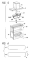
- FIG. 5 is an exploded perspective showing the whole arrangement of the gate valve, with the valve body and the valve seat separated from each other.
- valve seat 16 has a seal seat surface 110 which has a cross-section which is elongate with curved ends.
- the seal seat surface 110 is made up of a first seal surface 110A, two second seal surfaces 110B and 110B, and a third seal surface 110C.
- the first seal surface 110A is substantially conical, and forms an angle ⁇ with a horizontal plane B including an opening axis A-A and is tapered inwardly.
- the two second seal surfaces 110B and 110B are extended from the two arcuate portions R of the first seal surface 110A, forming an angle ⁇ with the horizontal plane B.
- the two seal surfaces 110B and 110B are connected through the third seal surface 110C.
- the valve seat 16 has an opening 20 extended in the direction of the opening axis A-A which is surrounded by those first through third seal surfaces 110A, 110B, 110B and 110C.
- a closed-box-shaped valve casing 60 is formed with the valve seat 16 set in the lower portion.
- a valve plate 40 is accommodated in the upper portion of the valve casing 60. That is, the valve plate 40 is engaged with the seal seat surface 110 which has a cross-section which is elongate with curved ends, thus opening and closing the opening 20.
- a seal material 30 is formed on the valve plate 40.
- the seal material 30 is made up of first through third seal material parts 30A, 30B, 30B and 30C which are integral with one another and are brought into close contact with the first through third seal surfaces 110A, 110B, 110B and 110C, respectively.
- the valve plate 40 is movable in a direction perpendicular to the horizontal plane B.
- the seal material 30 is so designed in dimension that it is brought into close contact with the first through third seal surfaces 110A, 110B, 110B and 110C.
- reference character 30AB designates T-shaped cross parts where the first seal material part 30A intersects with the second seal material parts 30B and 30B.
- a stem shaft 3 is connected to the center of the upper surface of the valve plate 40.
- the stem shaft 3 thus connected is extended through a bonnet flange 9 provided on the side of the valve body, and connected to a drive means 10 such as an air cylinder mounted on the flange 9.
- a sealing structure is provided which is of linear motion introduction type using a stretchable bellows (not shown in Fig. 5).
- the bonnet flange 9 is sealingly connected through a sealing part such as an O-ring to a bonnet flange 65 of the valve casing 60.
- the drive means 10 is adapted to move the valve plate 40 through the stem shaft 3.
- the gate valve of the invention is constructed as described above.
- the valve plate 40 When it is required to close the gate valve, the valve plate 40 is moved in the direction of axis perpendicular to the horizontal plane B; i.e., downwardly in FIG. 4 so that the seal material 30 on the valve 40 is pushed against the seal surfaces 110A, 110B, 110B and 110C of the valve seat 16; that is, the opening 20 is sealingly closed with the valve seat.
- the valve plate 40 is moved upwardly in FIG. 5 so that the opening 20 is opened.
- the angle ⁇ of the first seal surface 110A with respect to the horizontal plane B is equal to the angle ⁇ of each of the second seal surfaces 110B and 110B with respect to the latter B. If those angles are not equal, the seal surface 110A merges with the seal surfaces 110B and 110B forming smooth curved lines therebetween. Therefore, in the case where the angles of the seal surfaces are equal, the valve seat can be machined with ease. In view of the degree of slide between the seal surfaces and the seal material, and the degree of compression of the seal material, the angles of the seal surfaces should be about 60°. However, it is obvious that the same sealing effect can be obtained with other angles.
- the arcuate portions R of the first seal surface 110A and the first seal material part 30A engaged with the latter may be semi-circular in section as shown in the part (a) of FIG. 6, or they may be partly linear as indicated at X in the part (b) of FIG. 6, or they may be of other configurations similar to those mentioned above.
- third seal surface 110C is linear; for instance, it may be part of an arcuate surface.
- the valve plate 40 is provided in the valve casing 60 in such a manner that it is allowed to reciprocate between two positions to close and open a vacuum path formed therein, the stem shaft 3 connected to the valve plate 40 is loosely inserted into the through hole 11 formed in the bonnet flange 9 closing the valve casing 60, one end of the stretchable bellows 4, into which the stem shaft 3 is loosely inserted, is secured to the bonnet flange 9, while the other end of the bellows 4 is secured to the bellows movable flange 5 coupled to the stem shaft 3, and the bellows movable flange 5 is connected to the direct acting guide bearings 7 which are slidably guided by the direct acting guide shafts 8 provided outside the bellows 4.
- the slide guide mechanism made up of the direct acting guide bearings 7 and the direct acting guide shafts 8, is provided outside the bellows 4; i.e., outside the vacuum atmosphere.
- the vacuum gate valve of the invention is free from the difficulties accompanying the conventional vacuum gate valve that the stem shaft 3 and the bushing 30 gall each other, thus making it impossible to open and close the valve, and produce dust while wearing, which contaminates the pure vacuum atmosphere. Therefore, the vacuum gate valve of the invention is applicable to a semiconductor manufacturing device or the like which requires a pure vacuum atmosphere.
- the seal surface 110 which has a cross-section which is elongate with curved ends is formed on the valve seat 16.
- the seal seat surface 110 is made up of: the first seal surface 110A which is conical, and forms the angle ⁇ with the plane B including the opening axis A-A and is tapered inwardly; the second seal surfaces 110B and 110B extended from the two arcuate portions R of the first seal surface 110A, forming the angle ⁇ with the plane B; and the third seal surface 110C through which the seal surfaces 110B and 110B are connected to each other.
- the valve seat 16 has the opening 20 extended along the opening axis A-A, which is surrounded by the first through third seal surfaces 110A, 110B, 110B and 110C.
- the seal material 30 is formed on the valve body 40 which is engaged with the seal seat surface 110 to open and close the opening 20.
- the seal material 30 is made up of the first through third seal material parts 30A, 30B, 30B and 30C which are integral with one another and are brought into close contact with the first through third seal surfaces 110A, 110B, 110B and 110C, respectively.
- the valve body 40 is allowed to move in an axial direction perpendicular to the plane B. Hence, merely by moving the valve body 40 into and out of engagement with the seal seat surface 110, the gate valve can be closed and opened, and the sealing and unsealing can be achieved. That is, the gate valve of the invention, unlike the conventional one, has no mechanical slide parts, and accordingly no abrasion powder is formed.
- both sides (two opening ends) of the first seal material part 30A are supported by the valve seat 16 with the seal material 30 being held in close contact with the latter. Therefore, the gate valve of the invention is completely free from the difficulty that the valve body 40 is shifted by the difference in pressure between the chambers on both sides of the valve body. Thus, the opening can be positively sealingly closed.
Landscapes
- Engineering & Computer Science (AREA)
- General Engineering & Computer Science (AREA)
- Chemical & Material Sciences (AREA)
- Mechanical Engineering (AREA)
- Organic Chemistry (AREA)
- Chemical Kinetics & Catalysis (AREA)
- Materials Engineering (AREA)
- Metallurgy (AREA)
- Sliding Valves (AREA)
- Details Of Valves (AREA)
Claims (5)
- Dispositif de vanne pour ouverture et fermeture d'un passage, le dispositif de vanne comportant :un corps de vanne (60);un organe d'obturation (40) dans ledit corps de vanne, ledit organe d'obturation pouvant se déplacer de manière alternative entre deux positions afin de fermer et ouvrir le passage;un couvercle (9) destiné à fermer ledit corps, ledit couvercle ayant un trou débouchant (11);des moyens d'entraínement (10) prévus sur ledit couvercle afin d'entraíner de manière alternative ledit organe d'obturation, lesdits moyens d'entraínement ayant un arbre de tige (3) qui est inséré dans ledit trou débouchant, dans une relation sans contact avec celui-ci, et est relié au dit organe d'obturation;des moyens destinés à guider l'arbre de tige entre les deux positions; etdes moyens (4) destinés à isoler les moyens de guidage du passage; caractérisé en ce que :la vanne est une vanne pour vide;le passage est un passage sous vide; etledit corps de vanne comprend un siège de vanne (16), ledit siège de vanne ayant :une surface périphérique supérieure (110);une paire de surfaces latérales perpendiculaires à la surface supérieure;une ouverture (20) passant à travers lesdites surfaces latérales du siège de vanne;une première surface d'étanchéité périphérique (110A) qui forme un premier angle prédéterminé (a) par rapport à ladite surface supérieure (110) et est inclinée vers l'extérieur;une paire de deuxièmes surfaces d'étanchéité (110B) qui s'étendent entre les extrémités des surfaces latérales et forment un deuxième angle prédéterminé (β) par rapport à ladite surface supérieure (110), les deuxièmes surfaces d'étanchéité étant inclinées vers l'intérieur; etune troisième surface d'étanchéité inférieure (110C) par l'intermédiaire de laquelle lesdites surfaces latérales et les deuxièmes surfaces d'étanchéité sont reliées l'une à l'autre.
- Dispositif de vanne selon la revendication 1, dans lequel lesdits moyens d'entraínement comportent :des moyens de déplacement alternatif (13) destinés à actionner de manière alternative ledit arbre de tige,lesdits moyens de guidage comprenant,plusieurs arbres de guidage à action directe (8) qui s'étendent dans une direction qui est perpendiculaire à une surface dudit couvercle,plusieurs paliers de guidage à action directe (7) reliés chacun de façon coulissante à un arbre de guidage respectif, etune bride mobile (5) reliée au dit arbre de tige (3) et reliée de façon coulissante aux dits arbres de guidage à action directe par l'intermédiaire desdits paliers de guidage à action directe.
- Dispositif de vanne pour vide selon la revendication 2, dans lequel lesdits moyens d'isolation (4) comprennent un soufflet extensible prévu sensiblement coaxialement au dit arbre à tige, une extrémité dudit soufflet étant fixée au dit couvercle (9) et l'autre extrémité dudit soufflet étant fixée à la bride mobile de façon à entourer ledit arbre à tige.
- Dispositif de vanne selon la revendication 1, dans lequel ledit corps de vanne engage ledit siège de vanne (16) afin d'ouvrir et fermer ladite ouverture (20), et dans lequel ledit corps de vanne comprend :une plaque de vanne (40) reliée au dit arbre de tige (3); etun élément d'étanchéité (30) prévu sur ladite plaque de vanne, ledit élément d'étanchéité ayant une première partie d'étanchéité (30A), une deuxième partie d'étanchéité (30B) et une troisième partie d'étanchéité (30C) qui sont d'un seul tenant l'une avec l'autre et sont amenées en contact avec ladite première surface d'étanchéité (110A), ladite deuxième surface d'étanchéité (110B) et la troisième surface d'étanchéité (110C) respectivement lorsque la vanne est dans une position fermée.
- Vanne selon la revendication 1, dans laquelle :
l'ouverture (20) est dans une direction perpendiculaire aux dites surfaces.
Priority Applications (3)
| Application Number | Priority Date | Filing Date | Title |
|---|---|---|---|
| US07/841,817 US5271602A (en) | 1992-04-13 | 1992-02-26 | Vacuum gate valve |
| EP92303288A EP0565786B1 (fr) | 1992-04-13 | 1992-04-13 | Vanne pour vide |
| DE69224895T DE69224895T2 (de) | 1992-04-13 | 1992-04-13 | Vakuumschieber |
Applications Claiming Priority (1)
| Application Number | Priority Date | Filing Date | Title |
|---|---|---|---|
| EP92303288A EP0565786B1 (fr) | 1992-04-13 | 1992-04-13 | Vanne pour vide |
Publications (2)
| Publication Number | Publication Date |
|---|---|
| EP0565786A1 EP0565786A1 (fr) | 1993-10-20 |
| EP0565786B1 true EP0565786B1 (fr) | 1998-03-25 |
Family
ID=8211329
Family Applications (1)
| Application Number | Title | Priority Date | Filing Date |
|---|---|---|---|
| EP92303288A Expired - Lifetime EP0565786B1 (fr) | 1992-04-13 | 1992-04-13 | Vanne pour vide |
Country Status (3)
| Country | Link |
|---|---|
| US (1) | US5271602A (fr) |
| EP (1) | EP0565786B1 (fr) |
| DE (1) | DE69224895T2 (fr) |
Families Citing this family (17)
| Publication number | Priority date | Publication date | Assignee | Title |
|---|---|---|---|---|
| US5524663A (en) * | 1994-12-09 | 1996-06-11 | Unique Systems, Inc. | Vacuum tube shut-off for power tools |
| US5579718A (en) * | 1995-03-31 | 1996-12-03 | Applied Materials, Inc. | Slit valve door |
| US5909867A (en) * | 1998-05-27 | 1999-06-08 | Vat Holding Ag | Closing assembly for a chamber having a through-opening |
| RU2147349C1 (ru) * | 1998-08-25 | 2000-04-10 | Александрова Ариадна Тимофеевна | Затвор |
| US6698718B2 (en) | 2001-08-29 | 2004-03-02 | Wafermasters, Inc. | Rotary valve |
| FI117063B (fi) * | 2003-06-06 | 2006-05-31 | Outokumpu Oy | Venttiilin tiiviste |
| US20050268857A1 (en) * | 2004-06-02 | 2005-12-08 | Applied Materials, Inc. | Uniformly compressed process chamber gate seal for semiconductor processing chamber |
| US7841582B2 (en) * | 2004-06-02 | 2010-11-30 | Applied Materials, Inc. | Variable seal pressure slit valve doors for semiconductor manufacturing equipment |
| US7422653B2 (en) * | 2004-07-13 | 2008-09-09 | Applied Materials, Inc. | Single-sided inflatable vertical slit valve |
| US7806383B2 (en) * | 2007-06-01 | 2010-10-05 | Applied Materials, Inc. | Slit valve |
| DE102011001186A1 (de) * | 2011-01-17 | 2012-07-19 | Z & J Technologies Gmbh | Antrieb für ein Schieberventil und Schieberventil |
| EP2551565A1 (fr) * | 2011-07-28 | 2013-01-30 | VAT Holding AG | Soupape à vide et articulation de fermeture pour la fermeture étanche au gaz d'une trajectoire découlement à l'aide d'un déplacement linéaire |
| DK2647892T3 (en) * | 2012-04-03 | 2015-02-09 | Phönix Armaturen Werke Bregel Gmbh | Shooting extensively a shooting house |
| DE102014107174A1 (de) * | 2014-05-21 | 2015-11-26 | Thyssenkrupp Ag | Stellvorrichtung zur Betätigung eines Elementes innerhalb eines von Koksofengas durchströmten Gasraumes und Verfahren zum Betreiben der Stellvorrichtung |
| US10865536B1 (en) | 2019-02-20 | 2020-12-15 | Keith D. Olson | Scissors gate valve and system water management system |
| US11204104B2 (en) * | 2019-05-16 | 2021-12-21 | Tapcoenpro, Llc | Systems and methods for torque isolation valve actuator |
| CN110500418B (zh) * | 2019-08-07 | 2024-04-12 | 安徽省屯溪高压阀门股份有限公司 | 一种自控大口径快速切断波纹管闸阀 |
Citations (2)
| Publication number | Priority date | Publication date | Assignee | Title |
|---|---|---|---|---|
| GB1379675A (en) * | 1972-06-09 | 1975-01-08 | Montgomerie J B | Gate valve |
| DE2657205A1 (de) * | 1976-12-17 | 1978-06-22 | Lothar Gross | Dichtungselement, insbesondere fuer durchgangsventile o.dgl. |
Family Cites Families (15)
| Publication number | Priority date | Publication date | Assignee | Title |
|---|---|---|---|---|
| US2856151A (en) * | 1957-03-15 | 1958-10-14 | Melville F Peters | Fluid valve seals |
| FR1208769A (fr) * | 1957-11-22 | 1960-02-25 | Dewrance & Co | Perfectionnements aux dispositifs d'étanchéité |
| DE1223212B (de) * | 1962-09-29 | 1966-08-18 | Johannes Erhard | Dichtung fuer Absperrschieber |
| US3179372A (en) * | 1963-02-14 | 1965-04-20 | Norman U Vaudreuil | Gate valve |
| FR1482916A (fr) * | 1966-03-25 | 1967-06-02 | Perfectionnements aux vannes dont l'opercule porte un soufflet en matière plastique | |
| FR1603656A (fr) * | 1968-12-26 | 1971-05-10 | ||
| US4531539A (en) * | 1981-11-23 | 1985-07-30 | General Signal Corporation | Control valve for flow of solids |
| US4483514A (en) * | 1982-04-08 | 1984-11-20 | International Telephone And Telegraph Corporation | Gate member for resilient-seated gate valve |
| US4694634A (en) * | 1985-09-16 | 1987-09-22 | The Babcock & Wilcox Company | Vacuum sealing device for insulated steam injection tubing |
| DE3717724A1 (de) * | 1987-05-26 | 1988-12-08 | Schertler Siegfried | Ventilschieber mit einem schiebergehaeuse |
| JPS63312574A (ja) * | 1987-06-11 | 1988-12-21 | Nippon Kentetsu Co Ltd | 真空装置のゲ−トバルブ装置 |
| DE3801998C1 (fr) * | 1988-01-23 | 1989-05-18 | Schertler, Siegfried, Haag, Ch | |
| JPH01261573A (ja) * | 1988-04-08 | 1989-10-18 | Kokusai Electric Co Ltd | 真空仕切弁 |
| DE3831249A1 (de) * | 1988-09-14 | 1990-03-22 | Schertler Siegfried | Ventilschieber |
| US5058861A (en) * | 1990-02-26 | 1991-10-22 | Baumann Hans D | Bellows seal and method for assembling |
-
1992
- 1992-02-26 US US07/841,817 patent/US5271602A/en not_active Expired - Lifetime
- 1992-04-13 DE DE69224895T patent/DE69224895T2/de not_active Expired - Fee Related
- 1992-04-13 EP EP92303288A patent/EP0565786B1/fr not_active Expired - Lifetime
Patent Citations (2)
| Publication number | Priority date | Publication date | Assignee | Title |
|---|---|---|---|---|
| GB1379675A (en) * | 1972-06-09 | 1975-01-08 | Montgomerie J B | Gate valve |
| DE2657205A1 (de) * | 1976-12-17 | 1978-06-22 | Lothar Gross | Dichtungselement, insbesondere fuer durchgangsventile o.dgl. |
Also Published As
| Publication number | Publication date |
|---|---|
| US5271602A (en) | 1993-12-21 |
| DE69224895D1 (de) | 1998-04-30 |
| EP0565786A1 (fr) | 1993-10-20 |
| DE69224895T2 (de) | 1998-08-27 |
Similar Documents
| Publication | Publication Date | Title |
|---|---|---|
| EP0565786B1 (fr) | Vanne pour vide | |
| US5626324A (en) | Non-sliding vacuum gate valve | |
| US6390449B1 (en) | Gate valve | |
| US6629682B2 (en) | Vacuum valve | |
| US20010004106A1 (en) | Gate valve | |
| KR20070029558A (ko) | 유로의 본질적인 기밀 폐쇄를 위한 밸브 | |
| JP3678457B2 (ja) | 真空バルブのためのバルブ装置 | |
| KR870010343A (ko) | 역전 벨로우즈 밸브 | |
| US6453932B2 (en) | In-line valve | |
| KR20040024595A (ko) | 카운터 판의 후퇴가 지연되는 게이트 밸브 | |
| US5116023A (en) | Low vibration high vacuum gate valve | |
| US5839770A (en) | Robotic gripper | |
| KR900000602A (ko) | 솔레노이드로 작동되는 제어밸브가 있는 공압 액츄에이터 | |
| CA2914931A1 (fr) | Bagues d'actionneur ayant des joints integraux | |
| US20020056819A1 (en) | High-vacuum sealing gate valve with a single moving component | |
| US4223867A (en) | Valve with a pair of valve plates | |
| TWI900726B (zh) | 閥,特別是真空閥 | |
| KR100230936B1 (ko) | 진공게이트 밸브 | |
| JPH04262178A (ja) | 流体のための弁 | |
| EP1432937B1 (fr) | Ensemble joint d'etancheite de tige ou d'arbre | |
| JPH0726623Y2 (ja) | 真空ゲート弁 | |
| JPH0663579B2 (ja) | 弁駆動部 | |
| JP2002331487A (ja) | 把持装置 | |
| JPH0439446Y2 (fr) | ||
| JPH06129564A (ja) | バルブアクチェータ |
Legal Events
| Date | Code | Title | Description |
|---|---|---|---|
| PUAI | Public reference made under article 153(3) epc to a published international application that has entered the european phase |
Free format text: ORIGINAL CODE: 0009012 |
|
| AK | Designated contracting states |
Kind code of ref document: A1 Designated state(s): CH DE FR GB LI |
|
| 17P | Request for examination filed |
Effective date: 19940412 |
|
| 17Q | First examination report despatched |
Effective date: 19950913 |
|
| GRAG | Despatch of communication of intention to grant |
Free format text: ORIGINAL CODE: EPIDOS AGRA |
|
| GRAG | Despatch of communication of intention to grant |
Free format text: ORIGINAL CODE: EPIDOS AGRA |
|
| GRAH | Despatch of communication of intention to grant a patent |
Free format text: ORIGINAL CODE: EPIDOS IGRA |
|
| GRAH | Despatch of communication of intention to grant a patent |
Free format text: ORIGINAL CODE: EPIDOS IGRA |
|
| GRAA | (expected) grant |
Free format text: ORIGINAL CODE: 0009210 |
|
| AK | Designated contracting states |
Kind code of ref document: B1 Designated state(s): CH DE FR GB LI |
|
| REG | Reference to a national code |
Ref country code: CH Ref legal event code: EP Ref country code: CH Ref legal event code: NV Representative=s name: MICHELI & CIE INGENIEURS-CONSEILS |
|
| REF | Corresponds to: |
Ref document number: 69224895 Country of ref document: DE Date of ref document: 19980430 |
|
| ET | Fr: translation filed | ||
| PLBE | No opposition filed within time limit |
Free format text: ORIGINAL CODE: 0009261 |
|
| STAA | Information on the status of an ep patent application or granted ep patent |
Free format text: STATUS: NO OPPOSITION FILED WITHIN TIME LIMIT |
|
| 26N | No opposition filed | ||
| REG | Reference to a national code |
Ref country code: GB Ref legal event code: 732E |
|
| REG | Reference to a national code |
Ref country code: FR Ref legal event code: TP |
|
| REG | Reference to a national code |
Ref country code: CH Ref legal event code: PUE Owner name: THE JAPAN STEEL WORKS, LTD. TRANSFER- VALQUA SEIKI |
|
| REG | Reference to a national code |
Ref country code: GB Ref legal event code: IF02 |
|
| PGFP | Annual fee paid to national office [announced via postgrant information from national office to epo] |
Ref country code: CH Payment date: 20080415 Year of fee payment: 17 Ref country code: FR Payment date: 20080312 Year of fee payment: 17 Ref country code: DE Payment date: 20080417 Year of fee payment: 17 |
|
| PGFP | Annual fee paid to national office [announced via postgrant information from national office to epo] |
Ref country code: GB Payment date: 20080416 Year of fee payment: 17 |
|
| REG | Reference to a national code |
Ref country code: CH Ref legal event code: PL |
|
| GBPC | Gb: european patent ceased through non-payment of renewal fee |
Effective date: 20090413 |
|
| REG | Reference to a national code |
Ref country code: FR Ref legal event code: ST Effective date: 20091231 |
|
| PG25 | Lapsed in a contracting state [announced via postgrant information from national office to epo] |
Ref country code: DE Free format text: LAPSE BECAUSE OF NON-PAYMENT OF DUE FEES Effective date: 20091103 Ref country code: LI Free format text: LAPSE BECAUSE OF NON-PAYMENT OF DUE FEES Effective date: 20090430 Ref country code: CH Free format text: LAPSE BECAUSE OF NON-PAYMENT OF DUE FEES Effective date: 20090430 |
|
| PG25 | Lapsed in a contracting state [announced via postgrant information from national office to epo] |
Ref country code: GB Free format text: LAPSE BECAUSE OF NON-PAYMENT OF DUE FEES Effective date: 20090413 Ref country code: FR Free format text: LAPSE BECAUSE OF NON-PAYMENT OF DUE FEES Effective date: 20091222 |