EP0565954B1 - Schwelvorrichtung - Google Patents
Schwelvorrichtung Download PDFInfo
- Publication number
- EP0565954B1 EP0565954B1 EP93105354A EP93105354A EP0565954B1 EP 0565954 B1 EP0565954 B1 EP 0565954B1 EP 93105354 A EP93105354 A EP 93105354A EP 93105354 A EP93105354 A EP 93105354A EP 0565954 B1 EP0565954 B1 EP 0565954B1
- Authority
- EP
- European Patent Office
- Prior art keywords
- carbonization
- residue
- drum
- arrangement according
- discharge pipe
- Prior art date
- Legal status (The legal status is an assumption and is not a legal conclusion. Google has not performed a legal analysis and makes no representation as to the accuracy of the status listed.)
- Expired - Lifetime
Links
Images


Classifications
-
- C—CHEMISTRY; METALLURGY
- C10—PETROLEUM, GAS OR COKE INDUSTRIES; TECHNICAL GASES CONTAINING CARBON MONOXIDE; FUELS; LUBRICANTS; PEAT
- C10B—DESTRUCTIVE DISTILLATION OF CARBONACEOUS MATERIALS FOR PRODUCTION OF GAS, COKE, TAR, OR SIMILAR MATERIALS
- C10B1/00—Retorts
- C10B1/10—Rotary retorts
-
- C—CHEMISTRY; METALLURGY
- C10—PETROLEUM, GAS OR COKE INDUSTRIES; TECHNICAL GASES CONTAINING CARBON MONOXIDE; FUELS; LUBRICANTS; PEAT
- C10B—DESTRUCTIVE DISTILLATION OF CARBONACEOUS MATERIALS FOR PRODUCTION OF GAS, COKE, TAR, OR SIMILAR MATERIALS
- C10B53/00—Destructive distillation, specially adapted for particular solid raw materials or solid raw materials in special form
Definitions
- the invention relates to a smoldering device for smoldering goods containing metal parts, in particular waste materials that contain metal wires or metal strips, with the features of the preamble of patent claim 1.
- a smoldering device for smoldering waste materials is known from German Auslegeschrift 27 13 031. Waste is fed into a heated carbonization drum that can be rotated about its longitudinal axis. In the carbonization drum, the waste materials are carbonized into carbonization gas and solid carbonization residue. Smoldering gas and smoldering residue come out of the smoldering drum via a residue discharge pipe that is firmly connected to the smoldering drum and rotates with the smoldering drum. From there, the carbonization gas flows into a carbonization gas line, and the solid carbonization residue falls down into a discharge device. This can be followed by a transport system and / or a sorting device.
- Metal wires or metal strips can be contained in the waste materials to be smoldered. Spirals, springs and similar metal parts can also be found in the waste. Such metal parts come, for example, from steel belt tires, Bowden cables, cables, plastic composite materials or electrical appliances. After the waste materials have been introduced into the smoldering drum, the metal parts mentioned are exposed during the charring. This is due to the fact that at the temperatures of approx. 400 ° C to 700 ° C in a smoldering drum, most of the organic substances with which the metal parts are bonded to one another. Metal is not destroyed at the temperatures mentioned. The metal parts freed from plastic or rubber by the smoldering process are matted together by the rotating movement of the smoldering drum.
- a strand of vault is formed which can extend over the entire length of the smoldering drum.
- the diameter of this strand of vault can be approximately 20 to 30 cm.
- Some metal parts in particular steel carcasses made of steel belt tires and Bowden cables, are so stable that the resulting strand of vault does not break off even up to the discharge opening of the smoldering drum.
- the vault strand then moves endlessly out of the smoldering drum and reaches the discharge device for smoldering residue. This can block the discharge device.
- the discharge of the remaining smoldering residue is hindered. If a transport and sorting device is connected to the residual material discharge device, there is a risk that the operation of these devices is prevented by the vault. Then the entire smoldering device would be shut down.
- a smoldering device is known from US Pat. No. 3,794,565 in which drivers are arranged in the interior of a smoldering drum for loosening the material in the smoldering drum. These carriers are intended to prevent the formation of structures, so-called “frankfurters", which are hooked into one strand.
- the invention is based on the object of specifying a smoldering device of the type mentioned, in which even with stable metal parts, such as steel carcasses or Bowden cables, it is impossible for a bulge formed from metal parts to discharge smoldering residue and / or the subsequent transport and sorting hindered or even prevented by smoldering residue.
- the vaulted string moves at the lowest point of the carbonization drum and the residue discharge pipe. If the driver provided in accordance with the respective preamble of claims 1 and 2 meets the vault line, the vault line hangs on the driver and is raised in the waste material discharge pipe. When the driver has reached the highest point in the waste material discharge pipe, the vault falls down again. As a result of this mechanical stress, the vault strand is loosened and dissolved, so that only individual pieces of vault leave the waste material discharge pipe. These pieces are so small that they cannot hinder the further discharge of the solid residue and, if necessary, the sorting of the solid residue.
- a tear-off device in the area of the discharge opening in the area of the rising side of the rotatable waste material discharge pipe, a tear-off device is arranged with the tear-off edge directed downward, which cannot be rotated with the waste material discharge pipe. If the vault line through the carrier is raised, it is pressed against the tear-off edge and thereby torn off. Because the tear-off edge is directed downwards, the torn-off parts of the vault immediately fall down and reach the discharge device.
- the combination of driver and tear-off device can be used to break up a mechanically particularly stable vault.
- a combination of driver, rod and tear-off device is also possible.
- the driver can be arranged standing in the residue discharge tube on its inner surface. It can also be arranged on the waste material discharge pipe projecting beyond its discharge opening. With both embodiments, the vault string is raised. There can also be a plurality of preferably rod-shaped drivers arranged on the circumference of the residue discharge tube.
- the driver can also be arranged inclined at an angle in the direction of rotation of the residue discharge tube. This ensures particularly well that the vault strand is carried along by the driver. In particular, in the case of a combination of a driver and a tear-off device, it is ensured that the vault strand hits the tear-off edge of the tear-off device because it is pressed against the wall of the waste material discharge pipe by the inclined driver.
- the rod which does not rotate with the waste material discharge pipe, is arranged, for example, inclined downwards at an angle to the horizontal. As a result, torn pieces of vault always slide off the rod. No pieces of vault can get stuck on the stick.
- the tear-off device has, for example, the shape of a pair of scissors open at the bottom. This has the advantage that the can not slide past the tear-off device by the carrier raised vault. Rather, it gets into the opening of the scissors from where it cannot move to the side; it is torn down.
- the scissors can have an adjustable opening angle.
- the opening angle can be set so that, with a variable diameter of the vault line, it is always optimally received by the scissors.
- the tear-off device is curved away from the discharge opening, for example, in the direction of the longitudinal axis of the residue discharge pipe. This allows the vault strand to be inserted well.
- the tear-off device is arranged to be movable in the direction of the longitudinal axis of the waste material discharge pipe.
- the tear-off device can be designed as a pendulum. It can be connected in a pendulum-like manner above the discharge opening via a pendulum arm to a fixed system part. This has the advantage that the tear-off device, even if pipe movements occur in the axial direction, is always arranged directly at the discharge opening. This ensures that the vault strand can always be fed to the tear-off device.
- the residue discharge tube is connected in particular to a carbonization drum which can be rotated about its longitudinal axis or is part of a carbonization drum which can be rotated about its longitudinal axis.
- At least one driver for a vault line formed from the metal parts is arranged on the smoldering drum itself, and that the at least one driver is rotatable with the smoldering drum.
- the at least one driver protrudes into the interior of the carbonization drum.
- the vaulted string moves at the lowest point of the smoldering drum. If a carrier hits the vaulted string, it remains attached to the carrier and is raised in the smoldering drum. Due to the weight of the vaulted strand, pieces of vault are torn out with the driver. The vault strand dissolves. Only a few pieces of pebbles leave the smoldering drum. These pieces are so small that they cannot hinder the further discharge of the solid residue and, if necessary, the sorting of the solid residue.
- the driver or drivers is / are, for example, hook-shaped. This allows the vault line to be lifted well by the driver.
- the hook is curved so that it points upwards on the ascending side of the rotating smoldering drum.
- the at least one driver is arranged, for example, in the hot area of the smoldering drum. It can also be arranged in another area of the smoldering drum.
- the hot area is located in a smoldering drum immediately before the smoldering gas and residue are released.
- the arrangement of the driver in the hot area advantageously results in a mechanical separation of the vault strand where the vault strand is already impaired in its material strength by the high temperature.
- the at least one driver is attached to the inner surface of the carbonization drum.
- the at least one driver can also be fastened to the inner surface of the carbonization drum via a holding device.
- the holding device can be so long that the driver is arranged in an inner space of the carbonization drum that is free of internals.
- a smoldering drum can contain internals that are located on the inner surface. Even if gaps remain between these internals, a vault string will not form on these internals, but in the direction of the center of the smoldering drum. It is therefore advantageous if the driver is arranged directly above the internals instead of on the inner surface of the carbonization drum. The driver can be held in this position via the holding device.
- At least one additional driver can be arranged on the flank of the holding device.
- the vaulted strand is gripped even better by drivers staggered one behind the other on a holding device.
- the holding device can be a web, for example. This web can be connected directly to the smoldering drum or to a device permanently installed in the smoldering drum.
- the holding device can also be a support bracket for heating pipes or for another built-in part, which is already present in the smoldering drum.
- the heating pipes run on the inner surface of the smoldering drum and serve to heat the smoldering drum.
- the holding device can be a web connected to a support console, that is to say a combination of support console and web.
- the at least one driver can also be attached to a heating tube permanently installed in the carbonization drum or to another built-in part. It makes sense to choose one of the inner heating pipes so that the driver always protrudes into the space in the smoldering drum that is free of built-in components.
- the above-mentioned positioning of the at least one driver ensures that the vault strand always hits the driver.
- the drivers are arranged in alignment in the direction of the axis of rotation of the carbonization drum. You then lift the entire vault line at the same time.
- the drivers are arranged in the direction of the axis of rotation and distributed over the inner circumference of the carbonization drum.
- a strand of vault can be raised at different positions at different times. This results in one between two adjacent carriers Elongation of the vault line, which increases the mechanical stress on the vault line and facilitates tearing of the vault line.
- the drivers are arranged in a spiral distribution as seen in the direction of the axis of rotation of the smoldering drum.
- the vault string is raised evenly during one revolution.
- a waste material discharge pipe 1 is part of a smoldering device which is known, for example, from German specification 27 13 031.
- the residue discharge pipe 1 can be firmly connected to a carbonization drum 11 and can rotate together with this carbonization drum 11 about its longitudinal axis.
- the residue discharge tube 1 can also be part of the carbonization drum 11.
- Carbonization gas and solid carbonization residue are discharged through the residue discharge pipe 1. You get into a residue housing 2, which is fixed and in which the residue discharge pipe 1 opens. The carbonization gas rises while the solid carbonization residue falls down. In the drawing, only one wall of the residue housing 2 is shown.
- a strand of vault 4 can be formed from metal wires and other metal parts, which can clog the residue housing 2 and downstream system parts.
- a plate-shaped, preferably a rod-shaped driver 3a is arranged radially in the interior of the discharge tube 1 in the area of the discharge opening 1a.
- the driver 3a is arranged in the residue discharge tube 1 standing on its inner surface. With the rotational frequency of the residual material discharge tube 1, the driver 3a lifts the vault strand 4. As a result, the vault strand 4 can be broken down into individual pieces.
- a support or rod 5a is arranged below the residue discharge tube 1 on the stationary residue housing 2 for support. This protrudes in the axial direction beyond the end of the residue discharge tube 1, at which the discharge opening 1a is located.
- the vault strand 4 is e.g. held by the rod 5a and then raised by the driver 3a. As a result, the strand piece between these two components is torn.
- a plate-shaped or preferably a rod-shaped driver 3b is arranged on the residual material discharge pipe 1 projecting beyond its discharge opening 1a.
- a rod 5b is arranged at an angle to the horizontal inclined downwards on the fixed waste material housing 2.
- the vault strand 4 is raised by the driver 3b.
- the vault strand 4 can be torn between the driver 3b and the rod 5b. Since the rod 5b is arranged inclined downwards at an angle to the horizontal, separated pieces of the arch strand 4 immediately slide off the rod 5b and fall down.
- a non-inclined driver can also be used, which is similar to the drivers 3a or 3b, but is arranged inclined at an angle to the surface line of the residual material discharge pipe 1 in the direction of rotation.
- any other combination of one of the drivers mentioned, e.g. the driver 3a or 3b, and a rod 5a or 5b can be used.
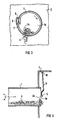
- a tear-off device 6 with a downwardly directed cutting edge or tear-off edge 7 is arranged in the region of the discharge opening 1 a in the region of the ascending (left) side of the residue discharge tube 1 before the end of the residue discharge tube 1.
- the tear-off device 6 cannot be rotated with the residue discharge pipe 1.
- the tear-off device 6 is fastened, for example, to the residue housing 2, which is only partially shown.
- a plate-shaped or preferably rod-shaped driver 3c is arranged in the waste material discharge pipe 1 standing on its inner surface and inclined at an angle in the direction of rotation of the waste material discharge pipe 1. The direction of rotation is indicated by an arrow.
- a vault strand 4 is gripped by the driver 3c when the residue discharge pipe 1 rotates, fed to the tear-off device 6 and severed at the tear-off edge 7. This process is repeated with the frequency of the rotary movement of the residue discharge tube 1.
- a radially arranged driver 3a (FIG. 1) or a driver 3b (FIG. 2) arranged in the longitudinal direction of the residue discharge tube 1 can also be used, provided that this is only sufficient the discharge opening 1a protrudes that it does not touch the tear-off device 6 during the rotational movement of the residue discharge pipe 1.
- the tear-off device 6 can be in the form of a pair of scissors open at the bottom. This ensures that the vault strand 4 cannot slide off the tear-off edge 7.
- the opening angle of the scissor-shaped tear-off device 6 can be adjustable. This is the Tear-off device 6 constructed from two legs which are connected to one another via a swivel joint 8.
- the adjustable tear-off device 6 can be adapted to the diameter of the arch strand 4.
- a tear-off device 6 is connected to the waste material housing 2 via a pendulum arm 9.
- the fulcrum 10 of the pendulum is positioned so that the tear-off device 6, which can be curved, is always in contact with the end face of the waste material discharge tube 1.
- the fulcrum 10 is located above the discharge opening 1a of the residue discharge tube 1.
- the fulcrum 10 is located on the left above the discharge opening 1a.
- the pivot point 10 can be located slightly to the right above the discharge opening 1a. This ensures that the tear-off device 6 always rests with a certain force on the end face of the waste material discharge pipe 1.
- a pipe movement in the axial direction to the left should not be expected.
- the pendulum which consists of the pendulum arm 9 and the tear-off device 6, is deflected to the right.
- the tear-off device 6 is always in contact with the expected expansions of the residue discharge pipe 1 on the end face of the residue discharge pipe 1.
- an arch section 4 at the outlet of the residue discharge pipe 1 can be divided into individual, relatively small pieces. Consequently the further treatment of the solid residue is not affected.
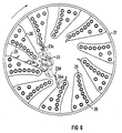
- a plurality of drivers 23a for the arch strand 22 are arranged in the smoldering drum 21 itself. These are connected to the inner surface of the carbonization drum 21 via straight webs 24. The webs 24 are necessary so that the drivers 23a are located in the interior of the carbonization drum 21 without any built-in components. Internals in the smoldering drum 21 can be heating pipes 25. A plurality of drivers 23b can also be fastened directly to the heating tubes 25 if it is ensured that the drivers 23b protrude into the interior of the carbonization drum 21 without any built-in components. The drivers 23a, 23b are - if they are in the ascending part of the carbonizing drum 21 - bent upward like a hook. The direction of rotation of the smoldering drum 21 is illustrated by an arrow.
- a driver 23c is arranged on the section of a support bracket 26 that is closest to the center of the carbonization drum 21.
- the support bracket 26 carries a plurality of heating pipes 25.
- a driver 23d can also be arranged on a web 24a, which is arranged supported on a support bracket 26.
- At least one additional driver 23e can also be arranged on the flank of the support bracket 26 or another holding device. As a result, the vault strand 22 can be detected even better.
- the drivers 23a-d, 23f are always located in the interior of the smoldering drum 21 without the installation.
- the internals can be heating pipes 25, support brackets 26 or other devices arranged in the carbonization drum 21.
- the holding device for a driver 23a-e can be a holding device 24 or 24a specially designed for this purpose.
- existing fixtures such as the support brackets 26 or other suitable fixtures can also serve as holding devices.
- Each hook-shaped driver 23a-f is bent such that it is curved upwards on the ascending side when the smoldering drum 21 is rotating. As a result, it optimally engages in the arched strand 22, lifts it and lets it fall down from the highest point of the smoldering drum 21.
- the vault strand 22 is torn apart by the mechanical stress.
- the drivers 23a-23f can therefore also be referred to as a tearing device.
- an arch of strands 22 in the smoldering drum 21 can be divided into individual pieces which cannot impair the further treatment of the solid residue.
Landscapes
- Chemical & Material Sciences (AREA)
- Oil, Petroleum & Natural Gas (AREA)
- Engineering & Computer Science (AREA)
- Materials Engineering (AREA)
- Organic Chemistry (AREA)
- Processing Of Solid Wastes (AREA)
- Processing And Handling Of Plastics And Other Materials For Molding In General (AREA)
- Enzymes And Modification Thereof (AREA)
- Steroid Compounds (AREA)
- Pharmaceuticals Containing Other Organic And Inorganic Compounds (AREA)
- Treatment Of Sludge (AREA)
- Vehicle Body Suspensions (AREA)
- Superconductors And Manufacturing Methods Therefor (AREA)
- Coke Industry (AREA)
- Incineration Of Waste (AREA)
- Muffle Furnaces And Rotary Kilns (AREA)
- Carbon And Carbon Compounds (AREA)
- Glass Compositions (AREA)
- Vaporization, Distillation, Condensation, Sublimation, And Cold Traps (AREA)
- Physical Deposition Of Substances That Are Components Of Semiconductor Devices (AREA)
Applications Claiming Priority (4)
| Application Number | Priority Date | Filing Date | Title |
|---|---|---|---|
| DE4212376A DE4212376A1 (de) | 1992-04-13 | 1992-04-13 | Schwelvorrichtung |
| DE4212376 | 1992-04-13 | ||
| DE4212377 | 1992-04-13 | ||
| DE4212377A DE4212377A1 (de) | 1992-04-13 | 1992-04-13 | Schwelvorrichtung |
Publications (2)
| Publication Number | Publication Date |
|---|---|
| EP0565954A1 EP0565954A1 (de) | 1993-10-20 |
| EP0565954B1 true EP0565954B1 (de) | 1997-09-03 |
Family
ID=25913930
Family Applications (1)
| Application Number | Title | Priority Date | Filing Date |
|---|---|---|---|
| EP93105354A Expired - Lifetime EP0565954B1 (de) | 1992-04-13 | 1993-03-31 | Schwelvorrichtung |
Country Status (13)
| Country | Link |
|---|---|
| US (1) | US5409577A (cs) |
| EP (1) | EP0565954B1 (cs) |
| JP (1) | JPH0641536A (cs) |
| AT (1) | ATE157695T1 (cs) |
| CA (1) | CA2093769A1 (cs) |
| CZ (1) | CZ58293A3 (cs) |
| DE (1) | DE59307232D1 (cs) |
| DK (1) | DK0565954T3 (cs) |
| ES (1) | ES2106215T3 (cs) |
| HU (1) | HU211819B (cs) |
| PL (1) | PL174354B1 (cs) |
| RU (1) | RU2094492C1 (cs) |
| SK (1) | SK31193A3 (cs) |
Families Citing this family (7)
| Publication number | Priority date | Publication date | Assignee | Title |
|---|---|---|---|---|
| GB2274908B (en) * | 1992-12-02 | 1996-08-14 | Pyrotech | Disposal of waste material |
| DE4329871A1 (de) * | 1993-09-03 | 1995-03-09 | Siemens Ag | Innenberohrte, drehbare Heizkammer für Abfall |
| ES2116609T5 (es) * | 1993-09-03 | 2002-01-16 | Siemens Ag | Camara de calentamiento giratoria para materiales solidos. |
| DE19822993C2 (de) * | 1998-05-22 | 2002-11-14 | Siemens Ag | Anlage zur Aufbereitung von Reststoff |
| DE602004010323T2 (de) | 2003-03-27 | 2008-03-13 | Nissan Chemical Industries, Ltd. | Diantimonpentoxidsol und Verfahren zur Herstellung |
| GB0710715D0 (en) * | 2007-06-05 | 2007-07-18 | London Environmental Res Ct Lt | Incineratot,such as municipal refuse incinerator |
| JP2010117113A (ja) * | 2008-11-14 | 2010-05-27 | Takuma Co Ltd | 回転ドラム |
Family Cites Families (24)
| Publication number | Priority date | Publication date | Assignee | Title |
|---|---|---|---|---|
| US1664723A (en) * | 1918-11-01 | 1928-04-03 | Young Niels | Degasification of coal |
| GB138472A (en) * | 1919-03-18 | 1920-02-12 | Vedrin Sa | Improvements in roasting furnaces for sulphurous ores |
| DE1019828B (de) * | 1954-08-07 | 1957-11-21 | Metallgesellschaft Ag | Wender fuer Drehrohroefen |
| US3224839A (en) * | 1961-04-06 | 1965-12-21 | Norman A Pierson | System for comminuting refuse |
| DE1558030B2 (de) * | 1966-03-23 | 1972-04-13 | Czkd Praha, Oborovy Podnik, Prag | Drehrohrofen zum brennen von pulverfoermigen materialien |
| BE752703A (fr) * | 1969-07-09 | 1970-12-01 | Kebe Anstalt Vertrieb | Perfectionnements apportes aux fours tubulaires rotatifs |
| DE2142766A1 (de) * | 1971-08-26 | 1973-03-15 | Smidth & Co As F L | Verfahren und vorrichtung zum waermeaustausch beim brennen von materialien in drehoefen |
| BE793206A (fr) * | 1971-12-22 | 1973-06-22 | Monsanto Co | Methode et appareil pour traiter des matieres thermo-decomposables, nongazeuses |
| DE2255069B2 (de) * | 1972-11-10 | 1977-03-03 | Polysius Ag, 4723 Neubeckum | Trommel zur thermischen behandlung von schleissendem gut |
| DE2707698C3 (de) * | 1977-02-23 | 1980-10-02 | Deutsche Anlagen-Leasing Service Gmbh, 6500 Mainz | Pyrolyse-Reaktor zur Umsetzung von Abfall |
| DE2709671C3 (de) * | 1977-03-05 | 1981-11-12 | Chadwell Newport Beach Calif. O'Connor | Drehrohrofen zur pyrolythischen Zersetzung von Stoffen |
| DE2713031C3 (de) * | 1977-03-24 | 1979-10-11 | Karl Dipl.-Ing. 7080 Goldshoefe Kiener | Schweltrommel |
| US4181495A (en) * | 1978-02-09 | 1980-01-01 | Bernt Jorgen O | Internal suspension preheater for long rotary kilns |
| DE2810838C3 (de) * | 1978-03-13 | 1982-07-22 | Herit AG, Vaduz | Drehtrommel zur Bildung thermischer Behandlungsräume für pyrolytische Zersetzungsfest- und -flüssigstoffe von Altbereifungen |
| US4301750A (en) * | 1978-03-15 | 1981-11-24 | Pan American Resources, Inc. | Method for pyrolyzing waste materials |
| US4205613A (en) * | 1978-03-15 | 1980-06-03 | Pan American Resources, Inc. | Apparatus for pyrolyzing waste materials |
| DE3004385C2 (de) * | 1980-02-06 | 1985-07-18 | Deutsche Kommunal-Anlagen Miete GmbH, 8000 München | Drehrohrofen zur Pyrolyse von Abfällen |
| AT386268B (de) * | 1981-04-10 | 1988-07-25 | Trunkenpolz Maschinen | Vorrichtung zum verbrennen von stroh, holzspaenen u.dgl. |
| DE3205366C2 (de) * | 1982-02-16 | 1984-06-07 | Deutsche Kommunal-Anlagen Miete GmbH, 8000 München | Austragsvorrichtung für einen Drehrohrofen |
| DE3230390A1 (de) * | 1982-08-14 | 1984-02-16 | odam, S.A., 67160 Wissembourg | Netzgeraet fuer einen defibrillator und defibrillator |
| DE3706771A1 (de) * | 1987-03-03 | 1988-09-22 | Gutehoffnungshuette Man | Drehtrommel zum verschwelen von abfaellen unter luftabschluss |
| DE3708224A1 (de) * | 1987-03-13 | 1988-09-22 | Krupp Polysius Ag | Drehtrommel zum waermeaustausch zwischen feststoffgut und gas |
| DE3736084A1 (de) * | 1987-10-24 | 1989-05-03 | Peters Ag Claudius | Drehtrommel zur erwaermung oder abkuehlung von schuettguetern |
| DE3835451A1 (de) * | 1988-10-18 | 1990-04-19 | Heinz Bergmann | Verfahren und vorrichtung zur temperaturbehandlung von abfaellen |
-
1993
- 1993-03-31 DK DK93105354.0T patent/DK0565954T3/da active
- 1993-03-31 DE DE59307232T patent/DE59307232D1/de not_active Expired - Fee Related
- 1993-03-31 EP EP93105354A patent/EP0565954B1/de not_active Expired - Lifetime
- 1993-03-31 AT AT93105354T patent/ATE157695T1/de active
- 1993-03-31 ES ES93105354T patent/ES2106215T3/es not_active Expired - Lifetime
- 1993-04-05 CZ CZ93582A patent/CZ58293A3/cs unknown
- 1993-04-07 PL PL93298421A patent/PL174354B1/pl unknown
- 1993-04-07 SK SK311-93A patent/SK31193A3/sk unknown
- 1993-04-08 HU HU9301036A patent/HU211819B/hu not_active IP Right Cessation
- 1993-04-08 CA CA002093769A patent/CA2093769A1/en not_active Abandoned
- 1993-04-12 RU RU9393004812A patent/RU2094492C1/ru active
- 1993-04-12 JP JP5108846A patent/JPH0641536A/ja not_active Withdrawn
- 1993-04-12 US US08/045,895 patent/US5409577A/en not_active Expired - Fee Related
Also Published As
| Publication number | Publication date |
|---|---|
| ATE157695T1 (de) | 1997-09-15 |
| CZ58293A3 (en) | 1994-04-13 |
| HU9301036D0 (en) | 1993-06-28 |
| PL174354B1 (pl) | 1998-07-31 |
| JPH0641536A (ja) | 1994-02-15 |
| SK31193A3 (en) | 1994-02-02 |
| DK0565954T3 (da) | 1998-04-27 |
| US5409577A (en) | 1995-04-25 |
| CA2093769A1 (en) | 1993-10-14 |
| ES2106215T3 (es) | 1997-11-01 |
| EP0565954A1 (de) | 1993-10-20 |
| PL298421A1 (en) | 1993-11-29 |
| HU211819B (en) | 1995-12-28 |
| HUT66351A (en) | 1994-11-28 |
| RU2094492C1 (ru) | 1997-10-27 |
| DE59307232D1 (de) | 1997-10-09 |
Similar Documents
| Publication | Publication Date | Title |
|---|---|---|
| WO1986007049A1 (fr) | Procede et appareil de sechage de boues de curage | |
| DE69512740T2 (de) | Verfahren und Vorrichtung zum Trennen von mindestens einem Stück eines Eingeweide-Gewebes von mindestens einem daran verbundenen Organs | |
| DE2531589C3 (de) | Drehofen | |
| EP0259547A1 (de) | Vorrichtung zum Entfernen von Rechen- und/oder Siebgut aus in einem Gerinne strömender Flüssigkeit | |
| EP0565954B1 (de) | Schwelvorrichtung | |
| EP1059023A2 (de) | Mähdrescher | |
| EP1348492B1 (de) | Pyrolyseanlage für Müll mit einer Siebvorrichtung für festen Reststoff | |
| EP2013148B1 (de) | Vorrichtung und verfahren zum trocknen von klärschlamm | |
| EP1079937B1 (de) | Trennvorrichtung für feststoff | |
| DE602004009311T2 (de) | Vorrichtung zur reinigung der flammröhren in einem kessel | |
| DE2513884B2 (de) | Vorrichtung zum Behandeln von unzerkleinerten Hopfendolden | |
| WO2019002248A1 (de) | Vorrichtung und verfahren zum entleeren von körnigem katalysatormaterial aus einem reaktor, insbesondere druckbehälter | |
| EP1088043B1 (de) | Anlage und verfahren zur aufbereitung von reststoff aus einer thermischen abfall-entsorgungsanlage | |
| DE69402686T2 (de) | Zentrifuge für schüttgut | |
| DE1782313B2 (de) | Vorrichtung zum reinigen von zuckerrueben-prueflingen | |
| EP0623712A2 (de) | Vorrichtung zum Entfernen von Abscheidegut aus einer Flüssigkeit | |
| DE4212376A1 (de) | Schwelvorrichtung | |
| DD154036A5 (de) | Verfahren und vorrichtung zum behandeln eines feststoffes mit einem stroemenden gas | |
| DE2039203A1 (de) | Vorrichtung zum Trocknen oder Befeuchten von Tabak od.dgl. | |
| DE556655C (de) | Beschickungsvorrichtung fuer Drehtrommeln, insbesondere Drehrohroefen | |
| DE2119645B2 (de) | Trocknungstrommel | |
| DE1692107C3 (de) | Vorrichtung zum kontinuierlichen Herstellen eines Räuchermittels | |
| DE888027C (de) | Geraet zum Ausheben und Umsetzen von Pflanzen | |
| DE968657C (de) | Vorrichtung zum Verteilen und Auseinanderziehen von in Haufen anfallendem Blattgut, insbesondere Tabakblaettern | |
| EP1704934A2 (de) | Räumvorrichtung für schwer zugängliche Kanäle |
Legal Events
| Date | Code | Title | Description |
|---|---|---|---|
| PUAI | Public reference made under article 153(3) epc to a published international application that has entered the european phase |
Free format text: ORIGINAL CODE: 0009012 |
|
| AK | Designated contracting states |
Kind code of ref document: A1 Designated state(s): AT BE CH DE DK ES FR GB IT LI LU NL SE |
|
| 17P | Request for examination filed |
Effective date: 19940414 |
|
| 17Q | First examination report despatched |
Effective date: 19960726 |
|
| GRAG | Despatch of communication of intention to grant |
Free format text: ORIGINAL CODE: EPIDOS AGRA |
|
| GRAH | Despatch of communication of intention to grant a patent |
Free format text: ORIGINAL CODE: EPIDOS IGRA |
|
| GRAH | Despatch of communication of intention to grant a patent |
Free format text: ORIGINAL CODE: EPIDOS IGRA |
|
| GRAA | (expected) grant |
Free format text: ORIGINAL CODE: 0009210 |
|
| AK | Designated contracting states |
Kind code of ref document: B1 Designated state(s): AT BE CH DE DK ES FR GB IT LI LU NL SE |
|
| REF | Corresponds to: |
Ref document number: 157695 Country of ref document: AT Date of ref document: 19970915 Kind code of ref document: T |
|
| REG | Reference to a national code |
Ref country code: CH Ref legal event code: NV Representative=s name: SIEMENS SCHWEIZ AG Ref country code: CH Ref legal event code: EP |
|
| REF | Corresponds to: |
Ref document number: 59307232 Country of ref document: DE Date of ref document: 19971009 |
|
| ET | Fr: translation filed | ||
| REG | Reference to a national code |
Ref country code: ES Ref legal event code: FG2A Ref document number: 2106215 Country of ref document: ES Kind code of ref document: T3 |
|
| GBT | Gb: translation of ep patent filed (gb section 77(6)(a)/1977) |
Effective date: 19971009 |
|
| ITF | It: translation for a ep patent filed | ||
| REG | Reference to a national code |
Ref country code: DK Ref legal event code: T3 |
|
| PLBE | No opposition filed within time limit |
Free format text: ORIGINAL CODE: 0009261 |
|
| 26N | No opposition filed | ||
| PGFP | Annual fee paid to national office [announced via postgrant information from national office to epo] |
Ref country code: AT Payment date: 19990303 Year of fee payment: 7 |
|
| PGFP | Annual fee paid to national office [announced via postgrant information from national office to epo] |
Ref country code: GB Payment date: 19990305 Year of fee payment: 7 |
|
| PGFP | Annual fee paid to national office [announced via postgrant information from national office to epo] |
Ref country code: DK Payment date: 19990309 Year of fee payment: 7 |
|
| PGFP | Annual fee paid to national office [announced via postgrant information from national office to epo] |
Ref country code: LU Payment date: 19990310 Year of fee payment: 7 |
|
| PGFP | Annual fee paid to national office [announced via postgrant information from national office to epo] |
Ref country code: BE Payment date: 19990312 Year of fee payment: 7 |
|
| PGFP | Annual fee paid to national office [announced via postgrant information from national office to epo] |
Ref country code: SE Payment date: 19990319 Year of fee payment: 7 |
|
| PGFP | Annual fee paid to national office [announced via postgrant information from national office to epo] |
Ref country code: NL Payment date: 19990322 Year of fee payment: 7 |
|
| PGFP | Annual fee paid to national office [announced via postgrant information from national office to epo] |
Ref country code: FR Payment date: 19990323 Year of fee payment: 7 |
|
| PGFP | Annual fee paid to national office [announced via postgrant information from national office to epo] |
Ref country code: ES Payment date: 19990325 Year of fee payment: 7 |
|
| PGFP | Annual fee paid to national office [announced via postgrant information from national office to epo] |
Ref country code: DE Payment date: 19990520 Year of fee payment: 7 |
|
| PGFP | Annual fee paid to national office [announced via postgrant information from national office to epo] |
Ref country code: CH Payment date: 19990617 Year of fee payment: 7 |
|
| PG25 | Lapsed in a contracting state [announced via postgrant information from national office to epo] |
Ref country code: LU Free format text: LAPSE BECAUSE OF NON-PAYMENT OF DUE FEES Effective date: 20000331 Ref country code: LI Free format text: LAPSE BECAUSE OF NON-PAYMENT OF DUE FEES Effective date: 20000331 Ref country code: GB Free format text: LAPSE BECAUSE OF NON-PAYMENT OF DUE FEES Effective date: 20000331 Ref country code: DK Free format text: LAPSE BECAUSE OF NON-PAYMENT OF DUE FEES Effective date: 20000331 Ref country code: CH Free format text: LAPSE BECAUSE OF NON-PAYMENT OF DUE FEES Effective date: 20000331 Ref country code: BE Free format text: LAPSE BECAUSE OF NON-PAYMENT OF DUE FEES Effective date: 20000331 Ref country code: AT Free format text: LAPSE BECAUSE OF NON-PAYMENT OF DUE FEES Effective date: 20000331 |
|
| PG25 | Lapsed in a contracting state [announced via postgrant information from national office to epo] |
Ref country code: SE Free format text: LAPSE BECAUSE OF NON-PAYMENT OF DUE FEES Effective date: 20000401 Ref country code: ES Free format text: LAPSE BECAUSE OF NON-PAYMENT OF DUE FEES Effective date: 20000401 |
|
| BERE | Be: lapsed |
Owner name: SIEMENS A.G. Effective date: 20000331 |
|
| PG25 | Lapsed in a contracting state [announced via postgrant information from national office to epo] |
Ref country code: NL Free format text: LAPSE BECAUSE OF NON-PAYMENT OF DUE FEES Effective date: 20001001 |
|
| REG | Reference to a national code |
Ref country code: CH Ref legal event code: PL |
|
| GBPC | Gb: european patent ceased through non-payment of renewal fee |
Effective date: 20000331 |
|
| REG | Reference to a national code |
Ref country code: DK Ref legal event code: EBP |
|
| PG25 | Lapsed in a contracting state [announced via postgrant information from national office to epo] |
Ref country code: FR Free format text: LAPSE BECAUSE OF NON-PAYMENT OF DUE FEES Effective date: 20001130 |
|
| NLV4 | Nl: lapsed or anulled due to non-payment of the annual fee |
Effective date: 20001001 |
|
| EUG | Se: european patent has lapsed |
Ref document number: 93105354.0 |
|
| REG | Reference to a national code |
Ref country code: FR Ref legal event code: ST |
|
| PG25 | Lapsed in a contracting state [announced via postgrant information from national office to epo] |
Ref country code: DE Free format text: LAPSE BECAUSE OF NON-PAYMENT OF DUE FEES Effective date: 20010103 |
|
| REG | Reference to a national code |
Ref country code: ES Ref legal event code: FD2A Effective date: 20011010 |
|
| PG25 | Lapsed in a contracting state [announced via postgrant information from national office to epo] |
Ref country code: IT Free format text: LAPSE BECAUSE OF NON-PAYMENT OF DUE FEES;WARNING: LAPSES OF ITALIAN PATENTS WITH EFFECTIVE DATE BEFORE 2007 MAY HAVE OCCURRED AT ANY TIME BEFORE 2007. THE CORRECT EFFECTIVE DATE MAY BE DIFFERENT FROM THE ONE RECORDED. Effective date: 20050331 |