EP0565968A2 - Dispositif de montage pour attacher des faisceaux de câbles - Google Patents
Dispositif de montage pour attacher des faisceaux de câbles Download PDFInfo
- Publication number
- EP0565968A2 EP0565968A2 EP93105472A EP93105472A EP0565968A2 EP 0565968 A2 EP0565968 A2 EP 0565968A2 EP 93105472 A EP93105472 A EP 93105472A EP 93105472 A EP93105472 A EP 93105472A EP 0565968 A2 EP0565968 A2 EP 0565968A2
- Authority
- EP
- European Patent Office
- Prior art keywords
- opening
- guide channel
- housing
- strap
- tape
- Prior art date
- Legal status (The legal status is an assumption and is not a legal conclusion. Google has not performed a legal analysis and makes no representation as to the accuracy of the status listed.)
- Granted
Links
Images

Classifications
-
- H—ELECTRICITY
- H05—ELECTRIC TECHNIQUES NOT OTHERWISE PROVIDED FOR
- H05K—PRINTED CIRCUITS; CASINGS OR CONSTRUCTIONAL DETAILS OF ELECTRIC APPARATUS; MANUFACTURE OF ASSEMBLAGES OF ELECTRICAL COMPONENTS
- H05K13/00—Apparatus or processes specially adapted for manufacturing or adjusting assemblages of electric components
- H05K13/06—Wiring by machine
-
- H—ELECTRICITY
- H02—GENERATION; CONVERSION OR DISTRIBUTION OF ELECTRIC POWER
- H02G—INSTALLATION OF ELECTRIC CABLES OR LINES, OR OF COMBINED OPTICAL AND ELECTRIC CABLES OR LINES
- H02G1/00—Methods or apparatus specially adapted for installing, maintaining, repairing or dismantling electric cables or lines
- H02G1/02—Methods or apparatus specially adapted for installing, maintaining, repairing or dismantling electric cables or lines for overhead lines or cables
- H02G1/04—Methods or apparatus specially adapted for installing, maintaining, repairing or dismantling electric cables or lines for overhead lines or cables for mounting or stretching
-
- H—ELECTRICITY
- H02—GENERATION; CONVERSION OR DISTRIBUTION OF ELECTRIC POWER
- H02G—INSTALLATION OF ELECTRIC CABLES OR LINES, OR OF COMBINED OPTICAL AND ELECTRIC CABLES OR LINES
- H02G7/00—Overhead installations of electric lines or cables
- H02G7/05—Suspension arrangements or devices for electric cables or lines
- H02G7/06—Suspensions for lines or cables along a separate supporting wire, e.g. S-hook
- H02G7/10—Flexible members or lashings wrapped around both the supporting wire and the line or cable
Definitions
- the invention relates to a mounting device for tying cable bundles by means of a plastic strapping provided with transverse ribs or tines of indefinite length and a locking lock also made of hard-elastic plastic, the lock known from DE 35 25 351 A1 with an opening for carrying the tensioning strap and with two interlocking tongues interacting with the transverse ribs or prongs is provided.
- the invention is based on a mounting device known from EP 0 303 723 A1.
- This essentially consists of a housing with a receiving part for the wound tensioning strap, an opening for exiting and re-entering the tensioning strap, a guide channel for feeding the tensioning strap to the opening, another channel arranged above the guide channel for feeding the locking locks in front of the outlet opening the tensioning strap, and a knife arranged behind the lock for severing the strap ends protruding from the locking lock.
- the object of the invention is therefore to design the aforementioned assembly device in such a way that the locking locks, which can be torn off by adhesive bars, are inserted into the assembly device and conveyed into the locking position in the manner in which they are ejected from the injection molding machines, and also that the tape is transported through the housing is trained to be more user-friendly.
- the assembly device shown in the figures is used for tying cable bundles by means of an endless plastic tension band in conjunction with locking locks, which are also made of hard elastic plastic.
- the tensioning straps described, for example, in DE 35 25 351 A1 are provided with transverse ribs or serrations and are first passed through the opening in the locking lock from one side and, after the cable bundle has been reclamped, inserted back into the same opening from the other side. In the opening are two mutually opposite, spring-loaded latching tongues that cooperate with the transverse ribs of the tension band.
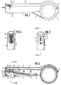
- the assembly device consists of a handy housing 1 with a receiving part 2 for the wound tension band 3.
- a guide channel 4 for the tension band 3 is provided in the interior of the housing, which can be pivoted at 5 in the housing 1 before its entry end 13 stored and with its outlet opening 14 is directed to a housing opening 6.
- the guide channel 4 is held in the upper position by means of a spring 7.
- a further channel 8 is arranged above this guide channel 4, which channel is designed to receive the locking locks 9.
- the channel 8 can be closed from above with a cover channel 10, which is pivotally connected to the housing 1 at 11 and can be closed at the front end by a latching mechanism (not shown).
- a pivotally mounted pawl 12 which is pressed by spring force against the upper edge of the hole of the lock 9 located just in front of the guide channel 4.
- the channel 8 is guided around to the exit end of the guide channel 4 in such a way that the locks 9, which are connected to one another by tear-off webs, can be inserted with their opening directly into the holding position in front of the tape exit opening 14 of the guide channel 4.
- the tightening strap 3 is driven by means of a roller 15 which can be rotated by hand, which is knurled on its peripheral surface 16 and can be pressed with it against the serrated tightening strap 3.
- the roller 15 is located below the guide channel 4 just before the tape exit opening 14 and protrudes with a part of its peripheral surface 16 from the housing 1, so that the roller 15 can be easily rotated with the index finger of the hand that holds the mounting device.
- a lever 17 is pivotally mounted in the housing 1 above the pivotable guide channel 4. This lever 17 carries in its front third a rotatably mounted roller 18 which rests on the front area of the guide channel 4. The lever 17 is extended somewhat beyond the roller bearing and has at its end 19 a laterally projecting pin 20 which understands laterally in an arcuate elongated hole 21 from the housing and can be pressed down manually against the force of the spring 7.
- a knife 22 is arranged in the housing 1 below the band exit 14 and its cutting edge 23 is directed towards the tensioning band.
- the tensioning band 3 is pressed onto the cutting edge 23 and cut off exactly between the band exit 14 and the locking lock 9, which is also pulled down by the band 3.
- the assembly device which is loaded with a tensioning roller 3 and chain-like interlocking locks 9, has its opening 6 in front of a cable bundle 24.
Landscapes
- Engineering & Computer Science (AREA)
- Manufacturing & Machinery (AREA)
- Microelectronics & Electronic Packaging (AREA)
- Basic Packing Technique (AREA)
- Package Frames And Binding Bands (AREA)
- Insertion, Bundling And Securing Of Wires For Electric Apparatuses (AREA)
- Clamps And Clips (AREA)
Applications Claiming Priority (2)
| Application Number | Priority Date | Filing Date | Title |
|---|---|---|---|
| DE4212789A DE4212789C1 (fr) | 1992-04-16 | 1992-04-16 | |
| DE4212789 | 1992-04-16 |
Publications (3)
| Publication Number | Publication Date |
|---|---|
| EP0565968A2 true EP0565968A2 (fr) | 1993-10-20 |
| EP0565968A3 EP0565968A3 (fr) | 1995-03-29 |
| EP0565968B1 EP0565968B1 (fr) | 1996-09-25 |
Family
ID=6456981
Family Applications (1)
| Application Number | Title | Priority Date | Filing Date |
|---|---|---|---|
| EP93105472A Expired - Lifetime EP0565968B1 (fr) | 1992-04-16 | 1993-04-02 | Dispositif de montage pour attacher des faisceaux de câbles |
Country Status (5)
| Country | Link |
|---|---|
| US (2) | US5351611A (fr) |
| EP (1) | EP0565968B1 (fr) |
| JP (1) | JP2566721B2 (fr) |
| DE (1) | DE4212789C1 (fr) |
| ES (1) | ES2094402T3 (fr) |
Cited By (3)
| Publication number | Priority date | Publication date | Assignee | Title |
|---|---|---|---|---|
| DE19828007C1 (de) * | 1998-06-24 | 1999-12-16 | Raymond A & Cie | Anordnung von Befestigungselementen für die Halterung von mit Kabelbändern umspannten Bündeln |
| EP1231144A1 (fr) * | 2001-02-12 | 2002-08-14 | Hellermann Tyton GmbH | Dispositif pour lier des objets au moyen d'une boucle |
| WO2013140119A3 (fr) * | 2012-03-21 | 2013-11-14 | Natural Biotechnology Sprl | Traitement préalable aux récoltes |
Families Citing this family (10)
| Publication number | Priority date | Publication date | Assignee | Title |
|---|---|---|---|---|
| DE3702840A1 (de) * | 1986-02-06 | 1987-08-20 | Ryobi Ltd | Anordnung verbundener metallteile und verfahren zu deren herstellung |
| DE19523870A1 (de) * | 1995-06-30 | 1997-01-02 | Mann & Hummel Filter | Ansaugeinrichtung aus thermoplastischem Kunststoff |
| DE29704400U1 (de) | 1997-03-11 | 1998-07-09 | Paul Hellermann GmbH, 25421 Pinneberg | Werkzeug zum Binden von Kabelbäumen |
| US5944944A (en) * | 1997-10-07 | 1999-08-31 | Gwo-Jiang; Liaw | Structural improvement of banding gun |
| USD412820S (en) | 1997-12-05 | 1999-08-17 | Ching Lu Lee | Hand held bundler |
| DE19859672C2 (de) * | 1998-12-23 | 2001-04-12 | Raymond A & Cie | Verfahren zum automatisierten Bündeln von Kabelsträngen und automatisch arbeitendes Gerät zur Durchführung des Verfahrens |
| JP3748504B2 (ja) * | 2000-02-24 | 2006-02-22 | 仁礼工業株式会社 | 結束装置 |
| EP1231158A1 (fr) * | 2001-02-12 | 2002-08-14 | Hellermann Tyton GmbH | Bande d'éléments de maintien pour liens et outil pour leur application |
| CN112498969B (zh) * | 2020-12-10 | 2025-05-30 | 苏州佳值电子工业有限公司 | 一种支撑式走线架模组及包装体 |
| CN113451918B (zh) * | 2021-08-03 | 2022-12-27 | 江西德伊智能电力有限公司 | 一种配电箱 |
Family Cites Families (10)
| Publication number | Priority date | Publication date | Assignee | Title |
|---|---|---|---|---|
| US3570554A (en) * | 1967-09-12 | 1971-03-16 | Hellermann Gmbh P | Method of tieing a bundle of cables |
| CH510944A (de) * | 1967-11-14 | 1971-07-31 | Hellermann Gmbh P | Werkzeug zum Binden von Kabelbäumen |
| US3489076A (en) * | 1968-05-20 | 1970-01-13 | Ty Lok Assembly Systems Inc | Automatic strapping apparatus |
| US3633633A (en) * | 1970-01-27 | 1972-01-11 | Ty Lok Assembly Systems Inc | Strapping apparatus |
| JPS5136680B2 (fr) * | 1973-03-26 | 1976-10-09 | ||
| JPS6121316A (ja) * | 1984-07-10 | 1986-01-30 | 株式会社 ニフコ | 結束工具 |
| DE3525351C2 (de) * | 1985-07-16 | 1994-09-15 | Raymond A Gmbh & Co Kg | Kabelbinder |
| IT1227770B (it) * | 1987-07-01 | 1991-05-06 | Rta Italiana Spa | Procedimento e attrezzatura per la legatura automatica di fasci di conduttori, per mezzo di una banda continua. |
| US4763700A (en) * | 1987-08-18 | 1988-08-16 | Nirei Industry Co., Ltd. | Binding tool |
| EP0303723B1 (fr) * | 1987-08-18 | 1993-11-10 | Nirei Industry Co. Ltd. | Outil de cerclage |
-
1992
- 1992-04-16 DE DE4212789A patent/DE4212789C1/de not_active Expired - Fee Related
-
1993
- 1993-04-02 EP EP93105472A patent/EP0565968B1/fr not_active Expired - Lifetime
- 1993-04-02 ES ES93105472T patent/ES2094402T3/es not_active Expired - Lifetime
- 1993-04-13 JP JP5085895A patent/JP2566721B2/ja not_active Expired - Lifetime
- 1993-04-15 US US08/046,307 patent/US5351611A/en not_active Expired - Fee Related
-
1994
- 1994-08-16 US US08/291,691 patent/US5471920A/en not_active Expired - Fee Related
Cited By (5)
| Publication number | Priority date | Publication date | Assignee | Title |
|---|---|---|---|---|
| DE19828007C1 (de) * | 1998-06-24 | 1999-12-16 | Raymond A & Cie | Anordnung von Befestigungselementen für die Halterung von mit Kabelbändern umspannten Bündeln |
| RU2222082C2 (ru) * | 1998-06-24 | 2004-01-20 | А.Раймон Энд Сие | Система крепежных элементов для крепления стянутых ленточными хомутами жгутов или пучков |
| EP1231144A1 (fr) * | 2001-02-12 | 2002-08-14 | Hellermann Tyton GmbH | Dispositif pour lier des objets au moyen d'une boucle |
| US6640839B2 (en) | 2001-02-12 | 2003-11-04 | Hellermann Tyton Gmbh | Arrangement for binding objects by means of a band loop |
| WO2013140119A3 (fr) * | 2012-03-21 | 2013-11-14 | Natural Biotechnology Sprl | Traitement préalable aux récoltes |
Also Published As
| Publication number | Publication date |
|---|---|
| US5351611A (en) | 1994-10-04 |
| EP0565968A3 (fr) | 1995-03-29 |
| JP2566721B2 (ja) | 1996-12-25 |
| JPH0645771A (ja) | 1994-02-18 |
| EP0565968B1 (fr) | 1996-09-25 |
| ES2094402T3 (es) | 1997-01-16 |
| DE4212789C1 (fr) | 1993-09-09 |
| US5471920A (en) | 1995-12-05 |
Similar Documents
| Publication | Publication Date | Title |
|---|---|---|
| EP0565968B1 (fr) | Dispositif de montage pour attacher des faisceaux de câbles | |
| DE3413099A1 (de) | Automatisch arbeitendes werkzeug zur herstellung von gebinden | |
| DE1761691B2 (de) | Handetikettiergeraet | |
| DE202008008960U1 (de) | Kunststoffschelle | |
| DE1515401B2 (de) | Handpresse zum Andrucken von Verb.n dungsklemmen an elektrische Leiter | |
| EP0835809B1 (fr) | Dispositif pour encercler un objet, en particulier un faisceau de câbles | |
| DE7211622U (de) | Kabelspannzange | |
| DE2536366B2 (de) | Bandführungseinrichtung für eine Bindemaschine | |
| EP0596363B1 (fr) | Arrangement pour encercler un objet | |
| DE60129759T2 (de) | Bindevorrichtung zum Spannen eines Bindestreifens | |
| DE69412976T2 (de) | Klebeband verwendende Bindemaschine und Kleberband hierfür | |
| DE2807056A1 (de) | Geraet zum bedrucken oder anbringen von selbsthaftenden etiketten | |
| EP0371044B1 (fr) | Outil de ficelage de faisceaux de cables ou similaires avec un ruban sans fin | |
| EP1231144B1 (fr) | Dispositif pour lier des objets au moyen d'une boucle | |
| DE3644657A1 (de) | Klebebandgehaeuse mit schneidevorrichtung | |
| EP0596368B1 (fr) | Arrangement pour ligaturer un objet, en particulier un faisceau de câbles | |
| EP0596370B1 (fr) | Arrangement de liage | |
| EP0659391B1 (fr) | Distributeur pour préportionner du ruban | |
| EP0864496B1 (fr) | Dispositif pour encercler des articles, en particulier des faisceaux de câbles | |
| DE3638882C2 (fr) | ||
| DE2626687A1 (de) | Handabroller, insbesondere fuer klebeband und dergleichen | |
| DE4339151C2 (de) | Bandabrollvorrichtung | |
| DE69829550T2 (de) | Ultraschall-bindewerkzeug | |
| EP0111515A1 (fr) | Appareil manuel pour le serrage des bandes pour lier des objets | |
| DE3135580A1 (de) | Verdrillbares schliessband |
Legal Events
| Date | Code | Title | Description |
|---|---|---|---|
| PUAI | Public reference made under article 153(3) epc to a published international application that has entered the european phase |
Free format text: ORIGINAL CODE: 0009012 |
|
| AK | Designated contracting states |
Kind code of ref document: A2 Designated state(s): BE ES FR GB IT NL SE |
|
| PUAL | Search report despatched |
Free format text: ORIGINAL CODE: 0009013 |
|
| AK | Designated contracting states |
Kind code of ref document: A3 Designated state(s): BE ES FR GB IT NL SE |
|
| 17P | Request for examination filed |
Effective date: 19950725 |
|
| GRAG | Despatch of communication of intention to grant |
Free format text: ORIGINAL CODE: EPIDOS AGRA |
|
| GRAH | Despatch of communication of intention to grant a patent |
Free format text: ORIGINAL CODE: EPIDOS IGRA |
|
| 17Q | First examination report despatched |
Effective date: 19960306 |
|
| GRAA | (expected) grant |
Free format text: ORIGINAL CODE: 0009210 |
|
| GRAH | Despatch of communication of intention to grant a patent |
Free format text: ORIGINAL CODE: EPIDOS IGRA |
|
| AK | Designated contracting states |
Kind code of ref document: B1 Designated state(s): BE ES FR GB IT NL SE |
|
| ITF | It: translation for a ep patent filed | ||
| GBT | Gb: translation of ep patent filed (gb section 77(6)(a)/1977) |
Effective date: 19961101 |
|
| ET | Fr: translation filed | ||
| REG | Reference to a national code |
Ref country code: ES Ref legal event code: FG2A Ref document number: 2094402 Country of ref document: ES Kind code of ref document: T3 |
|
| PLBE | No opposition filed within time limit |
Free format text: ORIGINAL CODE: 0009261 |
|
| 26N | No opposition filed | ||
| REG | Reference to a national code |
Ref country code: GB Ref legal event code: IF02 |
|
| PGFP | Annual fee paid to national office [announced via postgrant information from national office to epo] |
Ref country code: ES Payment date: 20030225 Year of fee payment: 11 |
|
| PGFP | Annual fee paid to national office [announced via postgrant information from national office to epo] |
Ref country code: GB Payment date: 20030331 Year of fee payment: 11 |
|
| PGFP | Annual fee paid to national office [announced via postgrant information from national office to epo] |
Ref country code: SE Payment date: 20030416 Year of fee payment: 11 |
|
| PGFP | Annual fee paid to national office [announced via postgrant information from national office to epo] |
Ref country code: BE Payment date: 20030423 Year of fee payment: 11 |
|
| PGFP | Annual fee paid to national office [announced via postgrant information from national office to epo] |
Ref country code: NL Payment date: 20030430 Year of fee payment: 11 |
|
| PG25 | Lapsed in a contracting state [announced via postgrant information from national office to epo] |
Ref country code: GB Free format text: LAPSE BECAUSE OF NON-PAYMENT OF DUE FEES Effective date: 20040402 |
|
| PG25 | Lapsed in a contracting state [announced via postgrant information from national office to epo] |
Ref country code: SE Free format text: LAPSE BECAUSE OF NON-PAYMENT OF DUE FEES Effective date: 20040403 Ref country code: ES Free format text: LAPSE BECAUSE OF NON-PAYMENT OF DUE FEES Effective date: 20040403 |
|
| PG25 | Lapsed in a contracting state [announced via postgrant information from national office to epo] |
Ref country code: BE Free format text: LAPSE BECAUSE OF NON-PAYMENT OF DUE FEES Effective date: 20040430 |
|
| BERE | Be: lapsed |
Owner name: FA A. *RAYMOND G.M.B.H. & CO. K.G. Effective date: 20040430 |
|
| PG25 | Lapsed in a contracting state [announced via postgrant information from national office to epo] |
Ref country code: NL Free format text: LAPSE BECAUSE OF NON-PAYMENT OF DUE FEES Effective date: 20041101 |
|
| GBPC | Gb: european patent ceased through non-payment of renewal fee | ||
| EUG | Se: european patent has lapsed | ||
| NLV4 | Nl: lapsed or anulled due to non-payment of the annual fee |
Effective date: 20041101 |
|
| PG25 | Lapsed in a contracting state [announced via postgrant information from national office to epo] |
Ref country code: IT Free format text: LAPSE BECAUSE OF NON-PAYMENT OF DUE FEES;WARNING: LAPSES OF ITALIAN PATENTS WITH EFFECTIVE DATE BEFORE 2007 MAY HAVE OCCURRED AT ANY TIME BEFORE 2007. THE CORRECT EFFECTIVE DATE MAY BE DIFFERENT FROM THE ONE RECORDED. Effective date: 20050402 |
|
| PGFP | Annual fee paid to national office [announced via postgrant information from national office to epo] |
Ref country code: FR Payment date: 20050516 Year of fee payment: 13 |
|
| REG | Reference to a national code |
Ref country code: ES Ref legal event code: FD2A Effective date: 20040403 |
|
| PG25 | Lapsed in a contracting state [announced via postgrant information from national office to epo] |
Ref country code: FR Free format text: LAPSE BECAUSE OF NON-PAYMENT OF DUE FEES Effective date: 20051230 |
|
| REG | Reference to a national code |
Ref country code: FR Ref legal event code: ST Effective date: 20051230 |