EP0567041B1 - Dispositif de chargement de cassette à levier de liaison unitaire - Google Patents
Dispositif de chargement de cassette à levier de liaison unitaire Download PDFInfo
- Publication number
- EP0567041B1 EP0567041B1 EP93106314A EP93106314A EP0567041B1 EP 0567041 B1 EP0567041 B1 EP 0567041B1 EP 93106314 A EP93106314 A EP 93106314A EP 93106314 A EP93106314 A EP 93106314A EP 0567041 B1 EP0567041 B1 EP 0567041B1
- Authority
- EP
- European Patent Office
- Prior art keywords
- loading
- cassette
- arm
- cassette holder
- linkage lever
- Prior art date
- Legal status (The legal status is an assumption and is not a legal conclusion. Google has not performed a legal analysis and makes no representation as to the accuracy of the status listed.)
- Expired - Lifetime
Links
Images

Classifications
-
- G—PHYSICS
- G11—INFORMATION STORAGE
- G11B—INFORMATION STORAGE BASED ON RELATIVE MOVEMENT BETWEEN RECORD CARRIER AND TRANSDUCER
- G11B15/00—Driving, starting or stopping record carriers of filamentary or web form; Driving both such record carriers and heads; Guiding such record carriers or containers therefor; Control thereof; Control of operating function
- G11B15/675—Guiding containers, e.g. loading, ejecting cassettes
- G11B15/67544—Guiding containers, e.g. loading, ejecting cassettes with movement of the cassette parallel to its main side and subsequent movement perpendicular thereto, i.e. front loading
- G11B15/67547—Guiding containers, e.g. loading, ejecting cassettes with movement of the cassette parallel to its main side and subsequent movement perpendicular thereto, i.e. front loading the two movements being made by the cassette holder
- G11B15/67549—Guiding containers, e.g. loading, ejecting cassettes with movement of the cassette parallel to its main side and subsequent movement perpendicular thereto, i.e. front loading the two movements being made by the cassette holder with servo control
-
- G—PHYSICS
- G11—INFORMATION STORAGE
- G11B—INFORMATION STORAGE BASED ON RELATIVE MOVEMENT BETWEEN RECORD CARRIER AND TRANSDUCER
- G11B15/00—Driving, starting or stopping record carriers of filamentary or web form; Driving both such record carriers and heads; Guiding such record carriers or containers therefor; Control thereof; Control of operating function
- G11B15/60—Guiding record carrier
-
- G—PHYSICS
- G11—INFORMATION STORAGE
- G11B—INFORMATION STORAGE BASED ON RELATIVE MOVEMENT BETWEEN RECORD CARRIER AND TRANSDUCER
- G11B15/00—Driving, starting or stopping record carriers of filamentary or web form; Driving both such record carriers and heads; Guiding such record carriers or containers therefor; Control thereof; Control of operating function
- G11B15/02—Control of operating function, e.g. switching from recording to reproducing
- G11B15/05—Control of operating function, e.g. switching from recording to reproducing by sensing features present on or derived from record carrier or container
- G11B15/06—Control of operating function, e.g. switching from recording to reproducing by sensing features present on or derived from record carrier or container by sensing auxiliary features on record carriers or containers, e.g. to stop machine near the end of a tape
- G11B15/08—Control of operating function, e.g. switching from recording to reproducing by sensing features present on or derived from record carrier or container by sensing auxiliary features on record carriers or containers, e.g. to stop machine near the end of a tape by photoelectric sensing
-
- G—PHYSICS
- G11—INFORMATION STORAGE
- G11B—INFORMATION STORAGE BASED ON RELATIVE MOVEMENT BETWEEN RECORD CARRIER AND TRANSDUCER
- G11B15/00—Driving, starting or stopping record carriers of filamentary or web form; Driving both such record carriers and heads; Guiding such record carriers or containers therefor; Control thereof; Control of operating function
- G11B15/02—Control of operating function, e.g. switching from recording to reproducing
- G11B15/16—Control of operating function, e.g. switching from recording to reproducing by sensing presence, absence or position of record carrier or container
- G11B15/17—Control of operating function, e.g. switching from recording to reproducing by sensing presence, absence or position of record carrier or container of container
-
- G—PHYSICS
- G11—INFORMATION STORAGE
- G11B—INFORMATION STORAGE BASED ON RELATIVE MOVEMENT BETWEEN RECORD CARRIER AND TRANSDUCER
- G11B15/00—Driving, starting or stopping record carriers of filamentary or web form; Driving both such record carriers and heads; Guiding such record carriers or containers therefor; Control thereof; Control of operating function
- G11B15/60—Guiding record carrier
- G11B15/66—Threading; Loading; Automatic self-loading
- G11B15/665—Threading; Loading; Automatic self-loading by extracting loop of record carrier from container
- G11B15/6653—Threading; Loading; Automatic self-loading by extracting loop of record carrier from container to pull the record carrier against drum
- G11B15/6656—Threading; Loading; Automatic self-loading by extracting loop of record carrier from container to pull the record carrier against drum using two-sided extraction, i.e. "M-type"
Definitions
- the present invention is directed to a cassette loading device for use with a video cassette recorder and, more particularly, to an improved tape cassette loading device which may carry out the cassette loading operation through the use of a unitary linkage lever in combination with a reversible speed reduction gadget and which has the ability to lock a loading arm against any inadvertent movement out of its final angular position.
- a video cassette recorder usually referred to as "VCR” by its acronym, includes a cassette loading device which is adapted to automatically transport a manually inserted tape cassette onto a reel table.
- the cassette loading device is provided with a cassette holder movable between a cassette reception position, a loading commencement position and a loading completion position. Placement of the tape cassette into the loading commencement position may be detected by a suitable sensor which, in turn, transmits a driving signal to an electric loading motor. In response, the electric motor is energized to bring the cassette holder together with the tape cassette into the loading completion position, thereby terminating a loading cycle of the tape cassette.
- Such a cassette loading process is distinguished from the so-called “tape loading” process which follows the cassette loading process.
- U.S. Patent No. 4,752,048 issued to Myung C. Paik which utilizes a reel motor as a power source to eliminate the need of a separate loading motor.
- the rotational force of the reel motor is selectively transmitted to a swingable loading arm through a belt-and-pulley combination so that the loading arm may rotate clockwise to cause a cassette holder to move toward a final loading position.
- a function plate is used to effect the selective transmission of the rotational force, in combination with a pivotable lever which is normally biased counterclockwise by a tension spring.
- U.S. Patent No. 4,628,382 to Y. Okumura discloses another prior art cassette loading device comprising a cassette holder for holding a cassette inserted through a cassette inlet, means for transporting the cassette from an insertion position to a completely loaded position by driving the cassette holder, and a reduction drive assembly for coupling the transportation means to a drive source.
- the reduction drive assembly includes a first drive mechanism having a small reduction ratio and engageable with the transportation means, when the cassette holder is located between the insertion position and the completely loaded position, and a second drive mechanism having a greater reduction ratio and engageable with the transportation means, when the cassette holder is brought to the completely loaded position or immediately therebefore.
- GB-A-2 232 806 discloses a cassette loading device, according to the preamble of claim 1, wherein an idling rotation mechanism in a housing of the video cassette tape recorder includes: the cassette loading device for loading and unloading a cassette into and out of a deck; a tape loading device for moving a video cassette tape into a position of magnetic transformation; a single motor for driving the cassette loading device and the tape loading device, said motor being able to rotate in clockwise and counterclockwise direction; and a loading cam device for preventing the tape loading device from being driven during the operation of the cassette loading device.
- no locking operation of the tape cassette holder in its loading position is provided.
- DE-A-37 40 947 discloses a magnetic tape cassette mechanism with a pair of photoelectric sensors located at a side end of the chassis to photoelectrically control a variety of operations of a VCR.
- a light beam which is generated from the photoelectrical sensor is returned by a mirror to the sensor.
- a cassette holder is provided with an encoding means such as a pair of grooves. When a tape cassette is inserted into the cassette holder and pushed, the sensors recognize the insertion of the tape cassette by way of the interrupt by the grooves.
- the cassette mechanism does not even use a unitary linkage lever for translating a rotary movement of a loading motor into a pivotal movement of a loading arm.
- cassette loading devices While the above and other prior art cassette loading devices are capable of performing their assigned task, needs have continued to exist for an improved cassette loading device which is more advantageous and desirable in terms of space requirements, manufacturing costs and operational reliability. More specifically, the known cassette loading devices have to employ a separate position sensor, e.g., a limit switch to detect the insertion of a tape cassette into the loading commencement position, which not only requires an additional space for the position sensor, but also increases the overall manufacturing cost of the video cassette recorder.
- a separate position sensor e.g., a limit switch to detect the insertion of a tape cassette into the loading commencement position
- a torsion spring or its equivalent is used in the conventional cassette loading devices to resiliently depress the cassette holder against a base plate of the video cassette recorder.
- Employing such a torsion spring is to, on one hand, counteract over-rotation of the loading motor beyond a predetermined angular extent and, on the other hand, to restrain any unwanted displacement of the cassette holder after the cassette loading operation has been completed.
- the torsion spring cannot resiliently depress the cassette holder against the base plate, thereby leaving the cassette holder and the tape cassette quite unstable.
- the loading motor over-rotates beyond the predetermined angular position, the loading arm and other components of the cassette loading devices are likely to be damaged, due to the severe stress exerted thereon by the loading motor.
- the prior art cassette loading devices usually make use of a worm-type speed reducer to lower the rotational speed of the loading motor to an acceptable level. Since the speed reducer heretofore used in the art lacks the ability to transmit the manual rotary force in the reverse direction, it has been necessary to employ a segmented, extendible linkage lever so as to permit the cassette holder to manually move from a cassette reception position toward a loading commencement position, even when the loading motor is not in operation. In addition, each segment of the linkage lever must be biased toward each other by a suitable tension spring to ensure positive power transmission through the linkage lever to the cassette holder, when the loading motor is energized to commence the automatic cassette loading process. This tends to increase the complexity of the cassette loading device, which may lead to an increased manufacturing cost of the video cassette recorder.
- Another object of the invention is to provide a cassette loading device which can lock a loading arm against any pivotal movement at the end of a cassette loading operation to keep a cassette holder free from an inadvertent displacement and which can positively accommodate unwanted under-rotation or over-rotation of a loading motor.
- a further object of the invention is to provide a cassette loading device that makes it possible to use a unitary linkage lever with no tension spring in order to operatively couple a cassette holder to a loading motor.
- a photoelectric sensor that has been used for the purpose of detecting an end-run of a magnetic tape is utilized in detecting the presence of a tape cassette in the loading commencement position to feed an electric driving signal to an electric motor.
- the photoelectric sensor includes a light emitter which continually projects a light beam along a given path and a pair of light receivers which serve to receive the projected light beam. Responsive to the driving signal, the electric motor is activated to cause a loading arm to swing from one angular position to another angular position. Rotary movement of the electric motor is translated into a pivotal movement of the loading arm by means of a unitary linkage lever.
- a light beam interrupter piece is carried by the linkage lever in such a way that, when the tape cassette is inserted into the loading commencement position, the light beam interrupter piece may cut off the projected light beam to enable the photoelectric sensor to generate the electrical driving signal.
- the linkage lever has a generally flat upright post which extends vertically upward therefrom to support the light beam interrupter piece at its free end.
- an arm locking finger extends from the flat upright post toward the loading arm in a substantially parallel relationship with respect to the second segment. As the cassette loading operation comes to an end, the arm locking finger is adapted to lock the loading arm against any pivotal movement.
- the inventive cassette loading device further includes a reversible speed reduction gadget which can transmit a manual rotary force in the reverse direction to allow the cassette holder to be manually pushed from the cassette reception position toward the loading completion position.
- a reversible speed reduction gadget which can transmit a manual rotary force in the reverse direction to allow the cassette holder to be manually pushed from the cassette reception position toward the loading completion position.
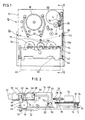
- a front-loading type video cassette recorder is shown to have a main chassis or deck, generally designated by reference numeral 10, which carries thereon various functional parts of the video cassette recorder.
- the main chassis 10 includes a rectangular bottom plate 12 and a pair of spaced parallel side walls 14, each of which extends vertically upward from opposite lateral edges of the bottom plate 12 and runs along a limited length of the latter.
- a reel table 16 is provided on the bottom plate 12 so that it can rotate the supply reel or the take-up reel of a tape cassette in a varying mode of operations.
- a head drum 18 that serves to record and reproduce video signals on and from a magnetic tape.
- the magnetic tape may be stretched out of the tape cassette and then wound around the head drum 18 by a pair of pole bases 20 which may slide along the corresponding curvilinear slots 22 formed through the thickness of the bottom plate 12.
- This is typically referred to as "tape loading”, as opposed to the cassette loading in which the novel features of the present invention reside.
- the curvilinear slots 22 are arranged in a substantially symmetrical pattern about the head drum 18 to form a mirror image with respect to each other.
- a loading motor 24 is affixed at the right-handed upper region of the bottom plate 12, which loading motor may be advantageously used, in the instant invention, to perform the cassette loading as well as the tape loading.
- the loading motor 24 is provided at its output shaft with a worm 26 which meshes with a worm wheel 28 to obtain a reduced rotational speed.
- the worm wheel 28 is rotatable about a stub axle 30 that carries a coaxial intermediate gear 30 at a suitable axial position below the worm wheel 28.
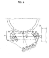
- the worm 26 and the worm wheel 28 constitute together a reversible speed reduction gadget 29 which will be fully set forth below with reference to Fig. 4.
- the intermediate gear 30 is engaging with a pinion or cam gear 32 of relatively large diameter to further reduce the rotational speed of the loading motor 24.
- the pinion 32 has an upper tooth array 34 extending over the full perimeter of the pinion 32 and a lower tooth array 36 running over a limited angular extent, e.g., 20 degrees, of the perimeter of the pinion 32.
- the pinion 32 is further provided with sinuous camming grooves at its opposite major surfaces, each of which is operatively connected to the pole bases 20 or other moving parts of the video cassette recorder through a suitable linkage mechanism.
- a cassette holder 38 is movably mounted between the side walls 14 for transporting the tape cassette 40 from a cassette reception position to a loading commencement position and, then, to a loading completion position.
- the cassette holder 38 has first and second slider pins 42 and 44 protruding horizontally from each lateral side thereof to fit into a first and a second guide slots 46 and 48, as clearly shown in Fig. 2.
- the "cassette reception position" is intended to mean a position wherein the cassette holder 38 is kept at rest to receive the tape cassette 40 just inserted through a cassette insertion opening(not shown) of the video cassette recorder.
- the "loading commencement position” refers to a position wherein the cassette holder 38 begins to move toward the reel table 16 by the rotational force of the loading motor 24 so as to initiate automatic loading of the tape cassette 40.
- the loading commencement position is spaced, e.g., 20mm, from the cassette reception position. Manual pushing force is used to advance the cassette holder 38 from the cassette reception position to the loading commencement position.
- the "loading completion position” it is meant a position wherein the automatic cassette loading comes to an end, with the result that the tape cassette 40 is placed on the reel table 16.
- a photoelectric sensor which includes a light emitter 50, e.g., light emitting diode, and a pair of light receivers 52, e.g., phototransistors.
- the light emitter 50 is located at a center of the bottom plate 12 to project a light beam along a light beam path as indicated by a broken line arrow.
- the light receivers 52 are respectively positioned at each of the opposite side walls 14 of the main chassis 10 in a symmetrical relation to one another to receive the light beam projected from the light emitter 50.
- the photoelectric sensor serves to stop the reel table 16 from further rotation at the time when the lengthwise end stretch of a magnetic tape is optically detected.
- the photoelectric sensor is also used to determine whether the cassette holder 38 is pushed into the loading commencement position from the cassette reception position. In case where the cassette holder 38 is determined to be in the loading commencement position, the photoelectric sensor will generate an electrical driving signal which enables the loading motor 24 to rotate in a forward direction so that the cassette holder 38 may be caused to displace from the loading commencement position toward the loading completion position. Description will be made later in more detail on how to detect the cassette holder which has been pushed into the loading commencement position.
- a swingable loading arm 54 is pivotably attached to at least one of the side walls 14 of the main chassis 10 for pivotal movement between a first angular position corresponding to the cassette reception position, a second angular position corresponding to the loading commencement position and a third angular position corresponding to the loading completion position.
- the loading arm 54 carries at its distal end the cassette holder 38 in a manner that the cassette holder 38 may be caused to move from the cassette reception position toward the loading completion position as the loading arm 54 is being subjected to the pivotal movement.
- the loading arm 54 has a sector-like tooth array 56 around its proximal end and a pair of parallelly extending legs 58 and 60 at its distal end, the legs defining therebetween a longitudinal slot 62 which is open at one end to receive the first slider pin 42 of the cassette holder 38.
- the leg 58 is provided with a pin-like projection 64 which extends from the free end of the leg 58 perpendicularly to the principal plane of the loading arm 54.
- the leg 60 has a cutout 66 which is open toward the longitudinal slot 62.
- a suitable torsion spring 68 is held on one surface of the loading arm 54, which consists of a horizontal extension retained by a protrusion 70 and a vertical extension running across the cutout 66 of the leg 60. As will be described below, the torsion spring 68 serves to resiliently urge the first slider pin 42 of the cassette holder 38 toward the bottom plate 12, only when the loading arm 54 is in the third angular position.
- a unitary or single piece linkage lever 72 which is slidably mounted on the bottom plate 12 of the main chassis 10 for translating the rotary movement of the loading motor 24 into the pivotal swinging movement of the loading arm 54.
- the linkage lever 72 is operatively connected, at one end, to the loading motor 24 through the pinion 32 and the reversible speed reduction gadget 29 and, at the other end, to the cassette holder 38 through the loading arm 54.
- the linkage lever 72 has a first rack 74 which is designed to mesh with the lower tooth array 36 of the pinion 32 and a second rack 76 which is in a meshing engagement with the sector-like tooth array 56 of the loading arm 54.
- the unitary linkage lever 72 has a generally flat upright post 78 that extends upward therefrom through a lateral slot 12a of the bottom plate 12.
- the upright post 78 terminates at a light beam interrupter piece 80 which is so shaped and arranged that, when the cassette holder 38 is in the loading commencement position, it can interrupt the light beam projected from the light emitter 50 to thereby enable the photoelectric sensor to generate an electrical driving signal.
- the light beam interrupter piece 80 is shown, by way of example, to have a generally rectangular configuration, the present invention is not limited thereto and, therefore, may employ an interrupter piece of different shape, whether circular or polygonal, as long as it can effectively interrupt or cut off the light beam at the loading commencement position.
- an arm locking finger 82 extends from the upright post 78 toward the loading arm 54 in a substantially parallel relationship with respect to the linkage lever 72.
- the arm locking finger 82 has a slant camming surface 84 for depressing the loading arm 54 into a final locking position and a horizontal bearing surface 86 for keeping the loading arm immovable in the locked position (see Fig.6).
- the camming surface 84 of the arm locking finger 82 may have a rounded or curved shape to ensure that smooth depressing action occur as the loading arm 54 is depressed into the locked position.
- the reversible speed reduction gadget 29 which consists of a worm 26 directly coupled to the loading motor 24 and a worm wheel 28 kept in a meshing engagement with the worm 26.
- the reversible speed reduction gadget 29 has the ability to transmit the rotational force of the worm wheel 28 to the worm 26 in the reverse direction. Such a reverse power transmission is required to enable the cassette holder 38 to be manually pushed from the cassette reception position toward the loading commencement position.
- Employing the reversible speed reduction gadget makes it possible to form the linkage lever 72 as a single piece and, further, to omit altogether the tension spring used in the conventional segmented linkage lever.
- the power transmission efficiency ⁇ should be above zero, which means that the lead angle ⁇ is greater than the friction angle ⁇ .
- the loading arm 54 lies in the first angular position with the cassette holder 38 in the cassette reception position, as depicted by a solid line. If the tape cassette 40 is inserted through a cassette insertion opening(not shown), the cassette holder 38 will receive it in a stable condition ready for transportation. Further pushing the tape cassette inwardly will cause the cassette holder 38 to move up to the loading commencement position, as depicted by a double-dotted phantom line in Fig. 2. Concurrently, the loading arm 54 is caused to swing toward the second angular position as shown by a double-dotted phantom line. In response, the unitary linkage lever 72 is pulled leftward a short distance, e.g., 20mm, which in turn causes the worm wheel 28 and the worm 26 to rotate in the reverse direction.
- a short distance e.g. 20mm
- the linkage lever 72 moves leftward in the manner stated above, the light beam interrupter piece 80 carried by the linkage lever 72 will be brought into a light beam blocking position as illustrated by a double-dotted phantom line in Fig. 2, thus interrupting the light beam projected from the light emitter 50.
- the light beam receiver 52 fails to receive the projected light beam, in which time the photoelectric sensor will generate an electrical driving signal.
- the electric loading motor 24 begins to rotate in a forward direction, the rotational force of which is transmitted to the loading arm 54 through the worm wheel 28, the intermediate gear 30, the pinion 32 and the linkage lever 72 in the stated sequence.
- the loading arm 54 is caused to swing from the second angular position toward the third angular position as shown in Fig. 5. This enables the cassette holder 38 to move from the loading commencement position toward the loading completion position. In this way, the tape cassette 40 can be transported onto the reel table 16.
- the linkage lever 72 may continue to travel leftward unless and until the loading motor 24 ceases its forward rotation.
- the slant camming surface 84 of the arm locking finger 82 comes into contact with the pin-like projection 64 of the loading arm 54 to depress it toward the bottom plate 12 of the main chassis 10 over a substantial period of time. This will allow for over-rotation or under-rotation of the loading motor 24 that may often occur at the end of cassette loading operation.
- the loading arm 54 will rotate clockwise within a significantly limited angular extent by the depressing force of the arm locking finger 82, making the pin-like projection 64 locked under the horizontal bearing surface 86 of the arm locking finger 82, as clearly depicted in Fig. 6.
- the first guide pin 42 of the cassette holder 38 is resiliently urged toward the bottom plate 12 by means of the torsion spring 68, which will keep the cassette holder 38 free from any inadvertent displacement out of the loading completion position.
Landscapes
- Automatic Tape Cassette Changers (AREA)
- Mechanical Control Devices (AREA)
- Feeding And Guiding Record Carriers (AREA)
- Transmission Devices (AREA)
- Gear Transmission (AREA)
Claims (6)
- Dispositif de chargement de cassette pour emploi avec un enregistreur de cassette vidéo du type comportant un châssis principal (10) composé d'une plaque inférieure (12) de forme générale rectangulaire, et d'une paire de parois latérales (14) parallèles et espacées, chacune s'étendant vers le haut depuis les bords latéraux de la plaque inférieure (12), ledit dispositif comportant:caractérisé par le faitun porte-cassette (38) monté, avec liberté de mouvement, entre les parois latérales (14) pour transporter une cassette de bande (40) depuis une position de réception de la cassette jusqu'à une position de commencement de chargement puis jusqu'à une position d'achèvement de chargement;un détecteur conçu pour générer un signal d'entraínement électrique chaque fois que le porte-cassette (38) est poussé dans la position de commencement de chargement;un bras du chargement oscillant (54) attaché, avec liberté de pivotement, à son extrémité arrière, à au moins l'une des parois latérales (14) pour exécuter un mouvement de pivotement entre une première, une seconde et une troisième positions angulaires, correspondant chacune à la positon de réception de la cassette, à la position de commencement de chargement et à la position d'achèvement de chargement du porte-cassette (38), respectivement, ledit bras de chargement (54) portant le porte-cassette (38) à son extrémité avant pour permettre au porte-cassette de se mouvoir entre la position de commencement de chargement et la position d'achèvement de chargement lorsqu'il est soumis au mouvement de pivotement;un moteur de chargement électrique (24) sensible au signal d'entraínement électrique provenant dudit détecteur pour faire en sorte que le bras de chargement (54) pivote pour passer de la seconde position angulaire à la troisième position angulaire de façon que le porte-cassette 38 puisse passer de la position de commencement de chargement à la position d'achèvement de chargement;un organe réversible (29) de réduction de la vitesse pour réduire la vitesse de rotation du moteur de chargement (24) à une valeur acceptable;un levier de liaison monopièce (72) monté, avec liberté de coulissement, sur la plaque inférieure (12) pour transformer un mouvement de rotation du moteur de chargement (24) en un mouvement oscillant de pivotement du bras de chargement (54), ledit levier de liaison (72) fonctionnellement relié, à une extrémité, au moteur électrique (24) par l'intermédiaire de l'organe réversible (29) de réduction de la vitesse et, à l'autre extrémité, au bras de chargement (54);que ledit détecteur est un détecteur photo-électrique incluant un émetteur de lumière situé au centre de la plaque inférieure (12) pour émettre un faisceau lumineux le long d'un chemin donné du faisceau lumineux, ainsi qu'une paire de récepteurs de lumière (52) positionnés sur les parois latérales pour recevoir le faisceau lumineux émis;que ledit levier de liaison (72) comprend un piquet vertical (78), de forme générale plate, qui s'étend vers le haut depuis le levier;qu'un doigt (82) de verrouillage du bras s'étend, depuis le piquet plat vertical (78), en direction du bras de chargement (54), substantiellement parallèlement au levier de liaison (72) de façon que le doigt (82) de verrouillage du bras puisse, à la troisième position angulaire du bras de chargement (54), le verrouiller à l'égard de tout mouvement de pivotement.
- Dispositif de chargement de cassette comme revendiqué dans la revendication 1, comportant en outre un élément interrupteur (80) du faisceau lumineux porté par le levier de liaison (72), ledit élément interrupteur présentant une forme et une disposition telles que, lorsque le porte-cassette (38) se trouve dans la position de commencement de chargement, il peut interrompre le faisceau lumineux, permettant ainsi au détecteur photo-électrique (50,52), de générer le signal d'entraínement électrique.
- Dispositif de chargement de cassette comme exposé dans la revendication 1, dans lequel ledit doigt (82) de verrouillage du bras présente une surface inclinée (84) formant came pour enfoncer le bras de chargement (54) en direction de la plaque inférieure (12) du châssis principal (10) ainsi qu'une surface horizontale (86) formant portée pour maintenir immobile le bras de chargement (54) dans la troisième position angulaire.
- Dispositif de chargement de cassette comme exposé dans la revendication 3, comportant en outre un ressort de torsion (68) monté sur le bras de chargement (54) pour contraindre élastiquement le porte-cassette (38) contre la plaque inférieure (12) lorsque le porte-cassette (38) se trouve dans la position d'achèvement du chargement.
- Dispositif de chargement de cassette comme exposé dans la revendication 1, dans lequel ladite vis sans fin (26) de l'organe (28) de réduction de la vitesse a un complément (β) de l'angle d'inclinaison qui est inférieur à son angle de friction (ρ).
- Dispositif de chargement de cassette comme exposé dans la revendication 5, dans lequel ledit complément (β) de l'angle d'inclinaison vaut environ 13,5 degrés.
Applications Claiming Priority (2)
| Application Number | Priority Date | Filing Date | Title |
|---|---|---|---|
| KR670092 | 1992-04-21 | ||
| KR1019920006700A KR940002912B1 (ko) | 1992-04-21 | 1992-04-21 | 워엄풀림을 이용한 비디오 테이프 레코더의 카세트 로딩장치 |
Publications (3)
| Publication Number | Publication Date |
|---|---|
| EP0567041A2 EP0567041A2 (fr) | 1993-10-27 |
| EP0567041A3 EP0567041A3 (fr) | 1994-11-17 |
| EP0567041B1 true EP0567041B1 (fr) | 1998-09-30 |
Family
ID=19332082
Family Applications (1)
| Application Number | Title | Priority Date | Filing Date |
|---|---|---|---|
| EP93106314A Expired - Lifetime EP0567041B1 (fr) | 1992-04-21 | 1993-04-19 | Dispositif de chargement de cassette à levier de liaison unitaire |
Country Status (9)
| Country | Link |
|---|---|
| US (1) | US5371641A (fr) |
| EP (1) | EP0567041B1 (fr) |
| JP (1) | JP2656713B2 (fr) |
| KR (1) | KR940002912B1 (fr) |
| AR (1) | AR247794A1 (fr) |
| BR (1) | BR9301614A (fr) |
| CA (1) | CA2094321C (fr) |
| DE (1) | DE69321281T2 (fr) |
| MY (1) | MY109589A (fr) |
Families Citing this family (10)
| Publication number | Priority date | Publication date | Assignee | Title |
|---|---|---|---|---|
| US5768241A (en) * | 1993-11-06 | 1998-06-16 | Asahi Kogaku Kogyo Kabushiki Kaisha | Shutter operating mechanism for magneto-optical disk drive |
| KR0147576B1 (ko) * | 1993-11-23 | 1998-10-15 | 김광호 | 카세트 로딩장치 |
| JP2730525B2 (ja) * | 1995-08-29 | 1998-03-25 | 松下電器産業株式会社 | 磁気記録再生装置 |
| KR0176553B1 (ko) * | 1995-12-27 | 1999-04-15 | 김광호 | 테이프 레코더의 카세트 안착장치 |
| KR970050658A (ko) * | 1995-12-30 | 1997-07-29 | 김광호 | 자기 기록 재생 장치 |
| JP3038705B2 (ja) * | 1996-11-06 | 2000-05-08 | 船井電機株式会社 | 磁気テープ装置 |
| JP3697911B2 (ja) * | 1998-10-02 | 2005-09-21 | ミツミ電機株式会社 | 磁気テープ記録再生装置 |
| JP2002298484A (ja) * | 2001-03-28 | 2002-10-11 | Mitsubishi Electric Corp | ディスクローディング装置 |
| US7216353B2 (en) * | 2001-03-28 | 2007-05-08 | Mitsubishi Denki Kabushiki Kaisha | Disk-loading apparatus |
| JP3577031B2 (ja) | 2001-12-03 | 2004-10-13 | Necパーソナルプロダクツ株式会社 | 磁気テープ装置のカートリッジロック機構 |
Family Cites Families (12)
| Publication number | Priority date | Publication date | Assignee | Title |
|---|---|---|---|---|
| JPH0619885B2 (ja) * | 1984-12-20 | 1994-03-16 | 三洋電機株式会社 | カセツトロ−デイング機構 |
| US4752048A (en) * | 1985-07-10 | 1988-06-21 | Gold Start Co., Ltd. | Front-loading mechanism of a videocassette recorder utilizing a reel motor as a power source |
| US4866551A (en) * | 1986-10-17 | 1989-09-12 | Matsushita Electric Industrial Co., Ltd. | Cassette loading apparatus |
| JPS6430053A (en) * | 1987-07-24 | 1989-01-31 | Akai Electric | Tape cassette loader |
| DE3740947A1 (de) * | 1987-12-03 | 1989-06-15 | Grundig Emv | Steuereinrichtung an einem magnetbandgeraet |
| JPH01292663A (ja) * | 1988-05-19 | 1989-11-24 | Mitsubishi Electric Corp | 磁気記録再生装置 |
| US5036413A (en) * | 1988-07-01 | 1991-07-30 | Matsushita Electric Industrial Co., Ltd. | Cassette loading apparatus having a supplemental force imparting unit |
| KR920007485Y1 (ko) * | 1989-06-09 | 1992-10-15 | 삼성전자 주식회사 | Vtr의 로딩캠을 이용한 하우징 공회전 장치 |
| JP2803267B2 (ja) * | 1989-12-27 | 1998-09-24 | 松下電器産業株式会社 | 磁気記録再生機のテープカセット装着装置 |
| JPH03286459A (ja) * | 1990-03-31 | 1991-12-17 | Toshiba Corp | カセット装填装置 |
| JP2754939B2 (ja) * | 1991-04-08 | 1998-05-20 | 松下電器産業株式会社 | カセット装着装置 |
| JPH0562314A (ja) * | 1991-09-05 | 1993-03-12 | Matsushita Electric Ind Co Ltd | カセツト装着装置 |
-
1992
- 1992-04-21 KR KR1019920006700A patent/KR940002912B1/ko not_active Expired - Fee Related
-
1993
- 1993-04-19 US US08/049,125 patent/US5371641A/en not_active Expired - Lifetime
- 1993-04-19 CA CA002094321A patent/CA2094321C/fr not_active Expired - Fee Related
- 1993-04-19 EP EP93106314A patent/EP0567041B1/fr not_active Expired - Lifetime
- 1993-04-19 DE DE69321281T patent/DE69321281T2/de not_active Expired - Fee Related
- 1993-04-20 BR BR9301614A patent/BR9301614A/pt not_active IP Right Cessation
- 1993-04-20 MY MYPI93000716A patent/MY109589A/en unknown
- 1993-04-20 JP JP5093341A patent/JP2656713B2/ja not_active Expired - Fee Related
- 1993-04-21 AR AR93324788A patent/AR247794A1/es active
Also Published As
| Publication number | Publication date |
|---|---|
| DE69321281T2 (de) | 1999-02-18 |
| JPH0644656A (ja) | 1994-02-18 |
| MY109589A (en) | 1997-03-31 |
| AR247794A1 (es) | 1995-03-31 |
| EP0567041A3 (fr) | 1994-11-17 |
| US5371641A (en) | 1994-12-06 |
| CA2094321A1 (fr) | 1993-10-22 |
| BR9301614A (pt) | 1993-10-26 |
| CA2094321C (fr) | 1996-11-19 |
| KR940002912B1 (ko) | 1994-04-07 |
| DE69321281D1 (de) | 1998-11-05 |
| KR930022319A (ko) | 1993-11-23 |
| EP0567041A2 (fr) | 1993-10-27 |
| JP2656713B2 (ja) | 1997-09-24 |
Similar Documents
| Publication | Publication Date | Title |
|---|---|---|
| EP0567041B1 (fr) | Dispositif de chargement de cassette à levier de liaison unitaire | |
| JPS60647A (ja) | カセツト装着装置 | |
| US4616274A (en) | Tape end detecting device for extractable tape type cassette | |
| US4851938A (en) | Cassette loading device | |
| JPH087910B2 (ja) | 記録再生装置 | |
| US5349482A (en) | Cassette loading device for use with a video cassette recorder | |
| US4985791A (en) | Cassette loading device | |
| JPS6010447A (ja) | カセツト装着装置 | |
| KR0147576B1 (ko) | 카세트 로딩장치 | |
| GB2045509A (en) | Interlock mechanism for tape player | |
| US6563667B1 (en) | Cassette deck mechanism for mounting/discharging different size cassettes using a pivoted arm | |
| US4620242A (en) | Apparatus for controlling a reversible tape drive in a magnetic tape player | |
| US4520412A (en) | Autostop mechanism for tape recorder | |
| JPH07121951A (ja) | ばねなしの分割形伝動レバーを有するカセットローディング装置 | |
| KR940002095B1 (ko) | 브이씨알 데크의 테이프 로딩장치 | |
| EP0045328B1 (fr) | Mécanisme de chargement pour un enregistreur de cassette à bande | |
| KR900004304Y1 (ko) | 테이프 레코더의 동력분리 전달 장치 | |
| JPS593380Y2 (ja) | テ−プレコ−ダの終端検出自動停止装置 | |
| US5880903A (en) | Cassette loading device in a video cassette recorder using a pressing member having a gear structure | |
| KR200142333Y1 (ko) | 테이프 레코더의 모드인식장치 | |
| KR970000498Y1 (ko) | 자기기록재생기의 카세트 로딩 감지장치 | |
| KR820002219Y1 (ko) | 카세트 테이프 레코더의 오토셔트 오프(auto shut off)장치 | |
| JPH03224159A (ja) | カセットテープ装着排出装置 | |
| JPH01264659A (ja) | カセットテープ装着装置 | |
| JPH0721642A (ja) | テープカセットローディング装置 |
Legal Events
| Date | Code | Title | Description |
|---|---|---|---|
| PUAI | Public reference made under article 153(3) epc to a published international application that has entered the european phase |
Free format text: ORIGINAL CODE: 0009012 |
|
| 17P | Request for examination filed |
Effective date: 19930419 |
|
| AK | Designated contracting states |
Kind code of ref document: A2 Designated state(s): DE FR GB IT |
|
| PUAL | Search report despatched |
Free format text: ORIGINAL CODE: 0009013 |
|
| AK | Designated contracting states |
Kind code of ref document: A3 Designated state(s): DE FR GB IT |
|
| 17Q | First examination report despatched |
Effective date: 19960923 |
|
| RIN1 | Information on inventor provided before grant (corrected) |
Inventor name: KIM, SEONG-TAE |
|
| GRAG | Despatch of communication of intention to grant |
Free format text: ORIGINAL CODE: EPIDOS AGRA |
|
| GRAG | Despatch of communication of intention to grant |
Free format text: ORIGINAL CODE: EPIDOS AGRA |
|
| GRAH | Despatch of communication of intention to grant a patent |
Free format text: ORIGINAL CODE: EPIDOS IGRA |
|
| GRAH | Despatch of communication of intention to grant a patent |
Free format text: ORIGINAL CODE: EPIDOS IGRA |
|
| GRAA | (expected) grant |
Free format text: ORIGINAL CODE: 0009210 |
|
| AK | Designated contracting states |
Kind code of ref document: B1 Designated state(s): DE FR GB IT |
|
| REF | Corresponds to: |
Ref document number: 69321281 Country of ref document: DE Date of ref document: 19981105 |
|
| ET | Fr: translation filed | ||
| PLBE | No opposition filed within time limit |
Free format text: ORIGINAL CODE: 0009261 |
|
| 26N | No opposition filed | ||
| REG | Reference to a national code |
Ref country code: GB Ref legal event code: IF02 |
|
| REG | Reference to a national code |
Ref country code: GB Ref legal event code: 732E |
|
| REG | Reference to a national code |
Ref country code: FR Ref legal event code: TP |
|
| PGFP | Annual fee paid to national office [announced via postgrant information from national office to epo] |
Ref country code: FR Payment date: 20080312 Year of fee payment: 16 Ref country code: DE Payment date: 20080424 Year of fee payment: 16 |
|
| PGFP | Annual fee paid to national office [announced via postgrant information from national office to epo] |
Ref country code: IT Payment date: 20080429 Year of fee payment: 16 |
|
| PGFP | Annual fee paid to national office [announced via postgrant information from national office to epo] |
Ref country code: GB Payment date: 20080423 Year of fee payment: 16 |
|
| GBPC | Gb: european patent ceased through non-payment of renewal fee |
Effective date: 20090419 |
|
| REG | Reference to a national code |
Ref country code: FR Ref legal event code: ST Effective date: 20091231 |
|
| PG25 | Lapsed in a contracting state [announced via postgrant information from national office to epo] |
Ref country code: DE Free format text: LAPSE BECAUSE OF NON-PAYMENT OF DUE FEES Effective date: 20091103 |
|
| PG25 | Lapsed in a contracting state [announced via postgrant information from national office to epo] |
Ref country code: GB Free format text: LAPSE BECAUSE OF NON-PAYMENT OF DUE FEES Effective date: 20090419 Ref country code: FR Free format text: LAPSE BECAUSE OF NON-PAYMENT OF DUE FEES Effective date: 20091222 |
|
| PG25 | Lapsed in a contracting state [announced via postgrant information from national office to epo] |
Ref country code: IT Free format text: LAPSE BECAUSE OF NON-PAYMENT OF DUE FEES Effective date: 20090419 |