EP0567268B1 - Vorrichtung zur Detektion des Fahrzeugkurses - Google Patents
Vorrichtung zur Detektion des Fahrzeugkurses Download PDFInfo
- Publication number
- EP0567268B1 EP0567268B1 EP93302905A EP93302905A EP0567268B1 EP 0567268 B1 EP0567268 B1 EP 0567268B1 EP 93302905 A EP93302905 A EP 93302905A EP 93302905 A EP93302905 A EP 93302905A EP 0567268 B1 EP0567268 B1 EP 0567268B1
- Authority
- EP
- European Patent Office
- Prior art keywords
- gyro
- error
- heading
- data
- vehicle
- Prior art date
- Legal status (The legal status is an assumption and is not a legal conclusion. Google has not performed a legal analysis and makes no representation as to the accuracy of the status listed.)
- Expired - Lifetime
Links
- 230000008859 change Effects 0.000 claims description 16
- 238000012545 processing Methods 0.000 claims description 10
- 238000000034 method Methods 0.000 description 11
- 239000006185 dispersion Substances 0.000 description 10
- 230000008569 process Effects 0.000 description 4
- 230000006870 function Effects 0.000 description 3
- 238000005070 sampling Methods 0.000 description 3
- 230000003247 decreasing effect Effects 0.000 description 2
- 238000010586 diagram Methods 0.000 description 2
- 238000013139 quantization Methods 0.000 description 2
- 238000009825 accumulation Methods 0.000 description 1
- 230000006978 adaptation Effects 0.000 description 1
- 238000007792 addition Methods 0.000 description 1
- 238000006243 chemical reaction Methods 0.000 description 1
- 238000012937 correction Methods 0.000 description 1
- 239000007788 liquid Substances 0.000 description 1
- 238000005259 measurement Methods 0.000 description 1
- 238000012986 modification Methods 0.000 description 1
- 230000004048 modification Effects 0.000 description 1
- 238000003672 processing method Methods 0.000 description 1
- 239000004065 semiconductor Substances 0.000 description 1
Images


Classifications
-
- G—PHYSICS
- G01—MEASURING; TESTING
- G01S—RADIO DIRECTION-FINDING; RADIO NAVIGATION; DETERMINING DISTANCE OR VELOCITY BY USE OF RADIO WAVES; LOCATING OR PRESENCE-DETECTING BY USE OF THE REFLECTION OR RERADIATION OF RADIO WAVES; ANALOGOUS ARRANGEMENTS USING OTHER WAVES
- G01S5/00—Position-fixing by co-ordinating two or more direction or position line determinations; Position-fixing by co-ordinating two or more distance determinations
- G01S5/02—Position-fixing by co-ordinating two or more direction or position line determinations; Position-fixing by co-ordinating two or more distance determinations using radio waves
- G01S5/12—Position-fixing by co-ordinating two or more direction or position line determinations; Position-fixing by co-ordinating two or more distance determinations using radio waves by co-ordinating position lines of different shape, e.g. hyperbolic, circular, elliptical or radial
-
- G—PHYSICS
- G01—MEASURING; TESTING
- G01C—MEASURING DISTANCES, LEVELS OR BEARINGS; SURVEYING; NAVIGATION; GYROSCOPIC INSTRUMENTS; PHOTOGRAMMETRY OR VIDEOGRAMMETRY
- G01C21/00—Navigation; Navigational instruments not provided for in groups G01C1/00 - G01C19/00
- G01C21/26—Navigation; Navigational instruments not provided for in groups G01C1/00 - G01C19/00 specially adapted for navigation in a road network
- G01C21/28—Navigation; Navigational instruments not provided for in groups G01C1/00 - G01C19/00 specially adapted for navigation in a road network with correlation of data from several navigational instruments
-
- G—PHYSICS
- G01—MEASURING; TESTING
- G01S—RADIO DIRECTION-FINDING; RADIO NAVIGATION; DETERMINING DISTANCE OR VELOCITY BY USE OF RADIO WAVES; LOCATING OR PRESENCE-DETECTING BY USE OF THE REFLECTION OR RERADIATION OF RADIO WAVES; ANALOGOUS ARRANGEMENTS USING OTHER WAVES
- G01S19/00—Satellite radio beacon positioning systems; Determining position, velocity or attitude using signals transmitted by such systems
- G01S19/38—Determining a navigation solution using signals transmitted by a satellite radio beacon positioning system
- G01S19/39—Determining a navigation solution using signals transmitted by a satellite radio beacon positioning system the satellite radio beacon positioning system transmitting time-stamped messages, e.g. GPS [Global Positioning System], GLONASS [Global Orbiting Navigation Satellite System] or GALILEO
- G01S19/42—Determining position
- G01S19/45—Determining position by combining measurements of signals from the satellite radio beacon positioning system with a supplementary measurement
- G01S19/47—Determining position by combining measurements of signals from the satellite radio beacon positioning system with a supplementary measurement the supplementary measurement being an inertial measurement, e.g. tightly coupled inertial
-
- G—PHYSICS
- G01—MEASURING; TESTING
- G01S—RADIO DIRECTION-FINDING; RADIO NAVIGATION; DETERMINING DISTANCE OR VELOCITY BY USE OF RADIO WAVES; LOCATING OR PRESENCE-DETECTING BY USE OF THE REFLECTION OR RERADIATION OF RADIO WAVES; ANALOGOUS ARRANGEMENTS USING OTHER WAVES
- G01S19/00—Satellite radio beacon positioning systems; Determining position, velocity or attitude using signals transmitted by such systems
- G01S19/38—Determining a navigation solution using signals transmitted by a satellite radio beacon positioning system
- G01S19/39—Determining a navigation solution using signals transmitted by a satellite radio beacon positioning system the satellite radio beacon positioning system transmitting time-stamped messages, e.g. GPS [Global Positioning System], GLONASS [Global Orbiting Navigation Satellite System] or GALILEO
- G01S19/53—Determining attitude
Definitions
- the present invention relates to an apparatus which detects the current heading of a vehicle with a gyro and a GPS (Global Positioning System) receiver.
- the invention also relates to an apparatus which detects the current location of such a vehicle.
- the gyro tends to generate an output (offset) due to the influence of temperatures or humidities, even when the gyro output should be zero during the time that the vehicle is in its stopped state or its straight traveling state.
- the offset of the gyro tends to drift due to changes in temperatures and humidities independently of whether the vehicle is in its stopped state or traveling state. Therefore, even if the gyro output during travel is corrected with an offset value obtained during the stop of the vehicle, a value after the offset correction will contain errors because of the aforementioned drift.
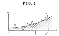
- Fig. 8 shows how the output of the gyro drifts with time, t. It will be seen from the figure that an actual offset value ⁇ n departs from an estimated offset value ⁇ ' measured at the time, to, during the stop of the vehicle. If the period of time from the start of the vehicle to the next stop of the vehicle is short, the drift of the gyro is small and can be corrected, but if the period of time from the start of the vehicle to the next stop of the vehicle is long, the drift of the gyro cannot be corrected and becomes larger and larger. In such a case, errors caused by the drift of the gyro are accumulated.
- a distance sensor As a method for providing information about the actual location of a vehicle traveling streets, there is known “dead reckoning", in which a distance sensor, a heading sensor (GPS receiver or gyro) and a processing unit for processing the distance and heading data acquired from the distance and heading sensors are employed and the current location data of the vehicle are acquired with an amount of distance change ⁇ L and an amount of heading change ⁇ (in a case where a gyro is used) or a heading ⁇ (in a case where a GPS receiver is used).
- the current location output data (Px, Py) of the vehicle are acquired by adding the calculated components ⁇ x and ⁇ y to the previous location output data (Px', Py').
- both the gyro and the GPS receiver are used. If either the angular velocity data of the gyro or the heading data of the GPS receiver will be reduced in reliability, one data can be compensated for by the other data. That is to say, the current heading of the vehicle can be estimated by calculating Kalman filter gain taking into consideration the characteristic errors inherently contained in the outputs of the gyro and the GPS receiver, and by processing the GPS receiver heading output and the gyro heading output with a weight processing method which is based on the calculated Kalman filter gain. However, in this method, it is important how the characteristic error components contained in the gyro output and the GPS receiver output are evaluated.
- the individual error components are evaluated by some method and if these components are set to constant values, the processing can be most easily performed.
- setting to the constant values is insufficient, and it is desirable to evaluate the error components accurately at real time by some method.
- the offset that is contained in the angular velocity data of the gyro varies with time, it is necessary to take into consideration the error in the angular velocity data resulting from that variation.
- the scale factor (output gain) of the gyro into consideration because sometimes the scale factor departs from a standard value.
- the inventor of the present application has proposed a heading detecting apparatus (Japanese Patent Laid-open Publication JP-A-3188316), which measures the outputs of the gyro and the GPS receiver and processes them at real time and is capable of accurately estimating the current heading of a vehicle with the aid of the output higher in reliability between the both outputs.
- a heading detecting apparatus Japanese Patent Laid-open Publication JP-A-3188316
- This apparatus only dispersion values that are contained in the final outputs of the gyro and the GPS receiver are measured, and individual error factors contained in the outputs of the gyro and the GPS receiver have not been taken into consideration.
- an important object of the present invention to provide an improved vehicle heading detecting apparatus which is capable of estimating the current heading of a vehicle accurately by individually analyzing and evaluating the error factors contained in the heading data of the GPS receiver and in the angular velocity data of the gyro and by determining the rate of use of the output data of the gyro and the GPS receiver.
- a heading detecting apparatus comprising a global positioning system receiver for outputting heading data of a vehicle, and a gyro for outputting angular velocity data of the vehicle.
- the heading detecting apparatus as shown in Fig. 9, further comprises first means (A), second means (B), and third means (C) connected to the global positioning system receiver.
- the first means (A) is connected to the gyro for calculating an error of an offset value that is contained in the angular velocity data of the gyro.
- the second means (B) is connected to the first means (A) for calculating an error that is contained in the angular velocity data of the gyro, on the basis of the error of the offset value calculated by the first means (A), a change rate of time of the error of the offset value multiplied by a predetermined time, and the angular velocity data of the gyro multiplied by an error of a scale factor of the gyro,
- the third means (C) is connected to the global positioning system receiver for calculating an error that is contained in the heading data of the global positioning system receiver and depends on at least a velocity of the vehicle.
- the heading detecting apparatus further comprises fourth means (D) and fifth means (E).
- the fourth means (D) is connected to the second means (B) and the third means (C) for calculating a Kalman filter gain by calculating a degree of reliability of the angular velocity data from the error of the angular velocity data of the gyro calculated by the second means (B) and a degree of reliability of the heading data from the error calculated by the third means (B).
- the fifth means (E) is connected to the fourth means (D) for calculating a current estimated heading of the vehicle by weight processing, on the basis of the Kalman filter gain, heading data obtained from the angular velocity data of the gyro and also the heading data outputted from the global positioning system receiver.
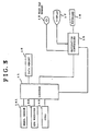
- FIG. 3 illustrates a preferred embodiment of a heading detecting apparatus of the present invention which may be employed in a vehicle location detecting apparatus.
- the location detecting apparatus comprises a wheel sensor 141 which senses the number of rotations of the left and right wheels (not shown) respectively of a vehicle (this sensor is used as a distance sensor), a GPS receiver 142, and a gyro 143.
- the location detecting apparatus further comprises a road map memory 12 for storing road map data, a locator 11 which calculates an estimated heading of a vehicle in accordance with the output data sensed by the gyro 143 and GPS receiver 142 and also calculates the location of the vehicle with the aid of the data of the wheel sensor 141, a data memory 16 connected to the locator 11, a display 17 connected to the navigation controller 15 for displaying the current location of the vehicle, and a keyboard 18 connected to the navigation controller 15.
- a road map memory 12 for storing road map data
- a locator 11 which calculates an estimated heading of a vehicle in accordance with the output data sensed by the gyro 143 and GPS receiver 142 and also calculates the location of the vehicle with the aid of the data of the wheel sensor 141
- a data memory 16 connected to the locator 11
- a display 17 connected to the navigation controller 15 for displaying the current location of the vehicle
- a keyboard 18 connected to the navigation controller 15.
- the data memory 16 connected to the locator 11 has stored therein a heading error r(v) that is contained in the data of the GPS receiver 142, an error qo of a gyro offset value that is contained in the angular velocity data w(t) of the gyro 143, a gyro noise N, an error a of the scale factor of the gyro 143, etc.
- the number of rotations of the wheel is obtained by counting the number of the pulses outputted from the wheel sensor 141 with a counter (not shown), and travel distance output data per unit time are calculated by multiplying the count data of the counter by a predetermined constant number indicative of a distance per one count.
- a relative change in the heading of the vehicle is obtained from the gyro 143. Then, based on the relative change and the absolute heading output data of the GPS receiver 142, the locator 11 calculates the heading output data of the vehicle, as will be described below.
- the road map memory 12 stores road map data of a predetermined area in advance and comprises a semiconductor memory, cassette tape, CD-ROM, IC memory, DAT or the like.
- the display 17 comprises a CRT display, crystalline liquid display or the like and displays a road map that the vehicle is traveling and a current location of the vehicle.
- the navigation controller 15 is constituted by a graphic processor, an image processing memory and the like, and generates instructions to perform a retrieval of the map on the display 17, switching of scale, scrolling, a display of the current location of the vehicle and the like.
- the angular velocity data w(t) of the gyro 143 and the heading data ⁇ (t) of the GPS receiver 142 are sampled every constant time. If it is assumed that the time from the previous process from the current process is ⁇ t, the number of samplings will be proportional to the time ⁇ t.
- the angular velocity data w(t) of the gyro as the vehicle is in its stopped state is normally zero, but the gyro generates an output if an offset occurs in the gyro.
- this gyro offset value a value that has been used during travel before the vehicle stops is to be used.
- the angular velocity data w(t) of the gyro during the stop of the vehicle can also be integrated and averaged.
- the error qo of the gyro offset value represents what extent of fluctuation the gyro offset value has, and is obtained by sampling a plurality of the angular velocity data w(t) of the gyro during stop and calculating a dispersion that is contained in the plurality of angular velocity data w(t) of the gyro.
- the estimated change rate ⁇ of the gyro offset error is a value that is obtained from experience as a function of temperature.
- the vehicle heading detecting process by the apparatus constructed as described above will hereinafter be described in detail.
- the location of the vehicle is displayed on the display 17 in accordance with the individual sensor output data stored in the locator 11.
- the data of each sensor are read in every constant time by break-in, and then the heading of the vehicle is updated.
- the vehicle heading detecting flow at the time of this break-in is shown in FIG. 4. It is noted that the break-in may also be made every constant distance that is obtained based on the output data indicative of the distances traveled by the vehicle.
- the above described constant time or distance is set, depending upon the type of the gyro and the functional performance of the GPS receiver.
- step (1) the velocity v of the vehicle, the angular velocity data w(t) of the gyro 143 and the heading data ⁇ (t) of the GPS receiver 142 are read in.
- step (2) the gyro offset value ⁇ , gyro offset error qo, change rate ⁇ of the gyro offset error, noise component N, and the gyro scale factor error ⁇ are read out of the data memory 16.
- step (2) advances to step (3), in which the fixed numbers a and b of the GPS heading error r(v) are read out of the data memory 16.
- the GPS heading error is not limited to this function.
- an error in the measurement of waves from the GPS as well as the velocity of the vehicle can be taken into consideration.
- the estimated heading of the vehicle is obtained based on each data read out of the data memory 6.
- r 2 (t) (av -1 + b) 2
- ⁇ (t) K(t) ⁇ (t) + (1 - K(t)))( ⁇ (t-1) + w(t))
- ⁇ (t) is a current heading
- ⁇ (t-1) is the previous heading
- w(t) and ⁇ (t) are sensor output data that are used as the current heading is calculated
- K(t) is a Kalman gain which is a variable of 0 ⁇ K(t) ⁇ 1.
- K(t) (q 2 (t) + ⁇ 2 (t-1))/(q 2 (t) + r 2 (t) + ⁇ 2 (t-1))
- the mean and dispersion of the estimated value of the gyro offset, the error of the change rate of that estimated value, the noise component, the error of the gyro scale factor, and the mean and dispersion of the error contained in the GPS receiver output have been calculated and stored. Then, when calculating the estimated heading of a vehicle, the dispersions that are contained in the output data of the gyro and GPS receiver are respectively calculated from the aforesaid stored data, and the estimated heading can be obtained based on the data that have been weighted.
Landscapes
- Engineering & Computer Science (AREA)
- Radar, Positioning & Navigation (AREA)
- Remote Sensing (AREA)
- Physics & Mathematics (AREA)
- General Physics & Mathematics (AREA)
- Computer Networks & Wireless Communication (AREA)
- Automation & Control Theory (AREA)
- Navigation (AREA)
Claims (3)
- Vorrichtung zur Erfassung des Fahrzeugkurses, bestehend aus einem Global-Positioning-System-Empfangsgerät (142) zum Ausgeben von Kursdaten eines Fahrzeugs und einem Kreisel (143) zum Ausgeben der Winkelgeschwindigkeitsdaten des Fahrzeugs, wobei die Vorrichtung dadurch gekennzeichnet ist, daß sie weiterhin besteht aus:einer ersten mit dem Kreisel (143) verbundenen Einrichtung (A) zum Errechnen eines Fehlers eines Abweichungswertes, der in den Winkelgeschwindigkeitsdaten des Kreisels (143) enthalten ist;einer zweiten mit der ersten Einrichtung (A) verbundenen Einrichtung (B) zum Errechnen eines Fehlers, der in den Winkelgeschwindigkeitsdaten des Kreisels (143) enthalten ist, auf der Basis des von der ersten Einrichtung (A) errechneten Fehlers des Abweichungswertes, einer Zeitänderungsrate des Fehlers des Abweichungswertes, multipliziert mit einer vorgegebenen Zeit, und der Winkelgeschwindigkeitsdaten des Kreisels (143), multipliziert mit einem Fehler eines Normierungsfaktors des Kreisels (143);einer dritten mit dem Global-Positioning-System-Empfangsgerät (142) verbundenen Einrichtung (C) zum Errechnen eines Fehlers, der in den Kursdaten des Global-Positioning-System-Empfangsgeräts (142) enthalten ist und von mindestens einer Geschwindigkeit des Fahrzeugs abhängt;einer vierten mit der zweiten Einrichtung (B) und der dritten Einrichtung (C) verbundenen Einrichtung (D) zum Errechnen eines Kalmanfilter-Verstärkungsfaktors durch das Berechnen eines Zuverlässigkeitsgrades der Winkelgeschwindigkeitsdaten aus dem Fehler der Winkelgeschwindigkeitsdaten des Kreisels (143), der mittels der zweiten Einrichtung (B) errechnet wurde, und eines Zuverlässigkeitsgrades der Kursdaten aus dem Fehler, der mittels der dritten Einrichtung (C) errechnet wurde; sowieeiner fünften mit der vierten Einrichtung (D) verbundenen Einrichtung (E) zum Errechnen eines aktuellen geschätzten Kurses des Fahrzeugs mittels Gewichtungsverarbeitung, auf der Basis des Kalmanfilter-Verstärkungsfaktors, der von den Winkelgeschwindigkeitsdaten des Kreisels (143) erhaltenen Kursdaten und auch der von dem Global-Positioning-System-Empfangsgerät (142) ausgegebenen Kursdaten.
- Vorrichtung zur Erfassung des Standorts, bestehend aus einer Meßwertgebereinrichtung (141) zum Erfassen von von einem Fahrzeug zurückgelegten Entfernungen, einem Global-Positioning-System-Empfangsgerät (142) zum Ausgeben der Kursdaten des Fahrzeugs und einem Kreisel (143) zum Ausgeben der Winkelgeschwindigkeitsdaten des Fahrzeugs, wobei die Vorrichtung dadurch gekennzeichnet ist, daß sie weiterhin besteht aus:einer ersten mit dem Kreisel (143) verbundenen Einrichtung (A) zum Errechnen eines Fehlers eines Abweichungswertes, der in den Winkelgeschwindigkeitsdaten des Kreisels (143) enthalten ist;einer zweiten mit der ersten Einrichtung (A) verbundenen Einrichtung (B) zum Errechnen eines Fehlers, der in den Winkelgeschwindigkeitsdaten des Kreisels (143) enthalten ist, auf der Basis des von der ersten Einrichtung (A) errechneten Fehlers des Abweichungswertes, einer Zeitänderungsrate des Fehlers des Abweichungswertes, multipliziert mit einer vorgegebenen Zeit, und der Winkelgeschwindigkeitsdaten des Kreisels (143), multipliziert mit einem Fehler eines Normierungsfaktors des Kreisels (143);einer dritten mit dem Global-Positioning-System-Empfangsgerät (142) verbundenen Einrichtung (C) zum Errechnen eines Fehlers, der in den Kursdaten des Global-Positioning-System-Empfangsgeräts (142) enthalten ist und von mindestens einer Geschwindigkeit des Fahrzeugs abhängt;einer vierten mit der zweiten Einrichtung (B) und der dritten Einrichtung (C) verbundenen Einrichtung (D) zum Errechnen eines Kalmanfilter-Verstärkungsfaktors durch das Berechnen eines Zuverlässigkeitsgrades der Winkelgeschwindigkeitsdaten aus dem Fehler der Winkelgeschwindigkeitsdaten des Kreisels (143), der mittels der zweiten Einrichtung (B) errechnet wurde, und eines Zuverlässigkeitsgrades der Kursdaten aus dem Fehler, der mittels der dritten Einrichtung (C) errechnet wurde; sowieeiner fünften mit der vierten Einrichtung (D) verbundenen Einrichtung (E) zum Errechnen eines aktuellen geschätzten Kurses des Fahrzeugs mittels Gewichtungsverarbeitung, auf der Basis des Kalmanfilter-Verstärkungsfaktors, der von den Winkelgeschwindigkeitsdaten des Kreisels (143) erhaltenen Kursdaten und auch der von dem Global-Positioning-System-Empfangsgerät (142) ausgegebenen Kursdaten; sowieeiner Standorterfassungseinrichtung (11), die mit der Meßwertgebereinrichtung (141), dem Global-Positioning-System-Empfangsgerät (142) und dem Kreisel (143) verbunden ist, wobei die Standorterfassungseinrichtung (11) einen aktuellen Standort des Fahrzeugs erfaßt, auf der Basis des aktuellen geschätzten Kurses, der von der fünften Einrichtung (E) errechnet wurde, und der von der Meßwertgebereinrichtung (141) erhaltenen Entfernungen.
- Vorrichtung zum Erfassen des Standorts nach Anspruch 2, die aus einem mit der Standorterfassungseinrichtung (11) verbundenen Datenspeicher (16), einem mit der Standorterfassungseinrichtung (11) verbundenen Navigationsregler (15), einem mit dem Navigationsregler (15) verbundenen Straßenkartenspeicher (12), einer mit dem Navigationsregler (15) verbundenen Anzeige (17) und einer mit dem Navigationsregler (15) verbundenen Tastatur (18) besteht.
Priority Applications (1)
| Application Number | Priority Date | Filing Date | Title |
|---|---|---|---|
| EP96200376A EP0716315A1 (de) | 1992-04-20 | 1993-04-15 | Vorrichtung zur Korrektion des Fahrzeugkurses |
Applications Claiming Priority (4)
| Application Number | Priority Date | Filing Date | Title |
|---|---|---|---|
| JP4099777A JP2514766B2 (ja) | 1992-04-20 | 1992-04-20 | 車両方位補正装置 |
| JP99778/92 | 1992-04-20 | ||
| JP99777/92 | 1992-04-20 | ||
| JP9977892A JPH06288776A (ja) | 1992-04-20 | 1992-04-20 | 方位検出装置 |
Related Child Applications (1)
| Application Number | Title | Priority Date | Filing Date |
|---|---|---|---|
| EP96200376.0 Division-Into | 1993-04-15 |
Publications (2)
| Publication Number | Publication Date |
|---|---|
| EP0567268A1 EP0567268A1 (de) | 1993-10-27 |
| EP0567268B1 true EP0567268B1 (de) | 1997-10-01 |
Family
ID=26440894
Family Applications (2)
| Application Number | Title | Priority Date | Filing Date |
|---|---|---|---|
| EP96200376A Withdrawn EP0716315A1 (de) | 1992-04-20 | 1993-04-15 | Vorrichtung zur Korrektion des Fahrzeugkurses |
| EP93302905A Expired - Lifetime EP0567268B1 (de) | 1992-04-20 | 1993-04-15 | Vorrichtung zur Detektion des Fahrzeugkurses |
Family Applications Before (1)
| Application Number | Title | Priority Date | Filing Date |
|---|---|---|---|
| EP96200376A Withdrawn EP0716315A1 (de) | 1992-04-20 | 1993-04-15 | Vorrichtung zur Korrektion des Fahrzeugkurses |
Country Status (3)
| Country | Link |
|---|---|
| US (1) | US5469158A (de) |
| EP (2) | EP0716315A1 (de) |
| DE (1) | DE69314219T2 (de) |
Cited By (1)
| Publication number | Priority date | Publication date | Assignee | Title |
|---|---|---|---|---|
| CN102520728A (zh) * | 2011-11-22 | 2012-06-27 | 北京空间机电研究所 | 一种采用双天线gps实现可控翼伞精确定点回收的方法 |
Families Citing this family (70)
| Publication number | Priority date | Publication date | Assignee | Title |
|---|---|---|---|---|
| US5657232A (en) * | 1993-03-17 | 1997-08-12 | Aisin Seiki Kabushiki Kaisha | Onboard positioning system |
| US5606506A (en) * | 1993-04-05 | 1997-02-25 | Caterpillar Inc. | Method and apparatus for improving the accuracy of position estimates in a satellite based navigation system using velocity data from an inertial reference unit |
| JPH07230315A (ja) * | 1994-02-16 | 1995-08-29 | Fuji Heavy Ind Ltd | 自律走行車の走行制御装置 |
| JPH07324941A (ja) * | 1994-06-02 | 1995-12-12 | Matsushita Electric Ind Co Ltd | オフセットドリフト補正装置 |
| US5512904A (en) * | 1994-06-13 | 1996-04-30 | Andrew Corporation | Method and apparatus of establishing a vehicle azimuth |
| JP3423418B2 (ja) * | 1994-06-30 | 2003-07-07 | 松下電器産業株式会社 | 移動体旋回角度算出装置 |
| EP0699894B1 (de) * | 1994-09-01 | 2002-03-27 | Aisin Aw Co., Ltd. | Navigationssystem |
| JP3483962B2 (ja) * | 1994-12-05 | 2004-01-06 | 株式会社ザナヴィ・インフォマティクス | 航法装置 |
| US5745868A (en) * | 1995-12-26 | 1998-04-28 | Motorola, Inc. | Method for rapid recovery from dead reckoning system heading loss |
| US6029111A (en) * | 1995-12-28 | 2000-02-22 | Magellan Dis, Inc. | Vehicle navigation system and method using GPS velocities |
| US5991692A (en) * | 1995-12-28 | 1999-11-23 | Magellan Dis, Inc. | Zero motion detection system for improved vehicle navigation system |
| US5862511A (en) * | 1995-12-28 | 1999-01-19 | Magellan Dis, Inc. | Vehicle navigation system and method |
| US5928309A (en) * | 1996-02-05 | 1999-07-27 | Korver; Kelvin | Navigation/guidance system for a land-based vehicle |
| US5808565A (en) * | 1996-02-20 | 1998-09-15 | E-Systems, Inc. | GPS triggered automatic annunciator for vehicles |
| JP3709610B2 (ja) * | 1996-05-24 | 2005-10-26 | トヨタ自動車株式会社 | 車載用衛星信号受信装置 |
| JP3627377B2 (ja) * | 1996-05-29 | 2005-03-09 | トヨタ自動車株式会社 | 車載用衛星信号受信装置 |
| JP3272960B2 (ja) * | 1996-08-19 | 2002-04-08 | 株式会社データ・テック | ドライビングレコーダ及び車両の運行解析装置 |
| JP3019008B2 (ja) * | 1996-10-11 | 2000-03-13 | 株式会社村田製作所 | 静磁波装置 |
| JPH10132843A (ja) * | 1996-10-25 | 1998-05-22 | Murata Mfg Co Ltd | 速度演算装置 |
| US5784029A (en) * | 1996-10-28 | 1998-07-21 | Motorola, Inc. | Recognition of and method and apparatus for GPS antenna lever arm compensation in integrated GPS/dead reckoning navigation systems |
| DE19645209B4 (de) * | 1996-11-02 | 2005-07-28 | Robert Bosch Gmbh | Ortungsvorrichtung für ein Kraftfahrzeug mit einem Satellitenempfänger und Ortungsverfahren |
| US5870689A (en) * | 1996-11-22 | 1999-02-09 | Case Corporation | Scouting system for an agricultural field |
| US5902343A (en) * | 1996-11-22 | 1999-05-11 | Case Corporation | Automatic scaling of GPS field maps |
| US5878371A (en) * | 1996-11-22 | 1999-03-02 | Case Corporation | Method and apparatus for synthesizing site-specific farming data |
| US5978723A (en) * | 1996-11-22 | 1999-11-02 | Case Corporation | Automatic identification of field boundaries in a site-specific farming system |
| US6253154B1 (en) * | 1996-11-22 | 2001-06-26 | Visteon Technologies, Llc | Method and apparatus for navigating with correction of angular speed using azimuth detection sensor |
| US5961573A (en) * | 1996-11-22 | 1999-10-05 | Case Corporation | Height control of an agricultural tool in a site-specific farming system |
| US6029106A (en) * | 1996-11-22 | 2000-02-22 | Case Corporation | Global position correction for the electronic display of field maps |
| US5938709A (en) * | 1996-11-22 | 1999-08-17 | Case Corporation | Panning display of GPS field maps |
| US6308134B1 (en) | 1996-12-27 | 2001-10-23 | Magellan Dis, Inc. | Vehicle navigation system and method using multiple axes accelerometer |
| US6230100B1 (en) * | 1997-01-31 | 2001-05-08 | Motorola, Inc. | Method and apparatus for differential scale factor calibration in differential odometry systems integrated with GPS |
| AU3201997A (en) * | 1997-02-14 | 1998-09-08 | Donovan Boedigheimer | A navigation/guidance system for a land-based vehicle |
| US5986547A (en) | 1997-03-03 | 1999-11-16 | Korver; Kelvin | Apparatus and method for improving the safety of railroad systems |
| DE19713516A1 (de) * | 1997-04-02 | 1998-10-22 | Graul Werner Dr Ing | Verfahren und Einrichtung zur passiven Bahnbestimmung eines Strahlungsemittenten |
| US6396446B1 (en) | 1999-02-16 | 2002-05-28 | Gentex Corporation | Microwave antenna for use in a vehicle |
| US6166698A (en) * | 1999-02-16 | 2000-12-26 | Gentex Corporation | Rearview mirror with integrated microwave receiver |
| US6456935B1 (en) | 2000-03-28 | 2002-09-24 | Horizon Navigation, Inc. | Voice guidance intonation in a vehicle navigation system |
| DE10023586A1 (de) * | 2000-05-13 | 2001-07-19 | Daimler Chrysler Ag | Vorrichtung zur Fahrzeugpositionsbestimmung mit mehreren Sensoreinheiten |
| US6697752B1 (en) | 2000-05-19 | 2004-02-24 | K&L Technologies, Inc. | System, apparatus and method for testing navigation or guidance equipment |
| US6581000B2 (en) * | 2001-01-04 | 2003-06-17 | Carnegie Mellon University | Position location system and method |
| US6577952B2 (en) * | 2001-01-08 | 2003-06-10 | Motorola, Inc. | Position and heading error-correction method and apparatus for vehicle navigation systems |
| RU2205417C2 (ru) * | 2001-05-28 | 2003-05-27 | Общество с ограниченной ответственностью "Ратеос" | Многоканальный приемоиндикатор спутниковых радионавигационных систем |
| DE10238061B4 (de) * | 2002-08-20 | 2005-06-02 | Litef Gmbh | Verfahren zur Bestimmung und Kompensation des durch Wellenlängenänderung verursachten Skalenfaktorfehlers in einem GPS-gestützten INS-System |
| KR100486505B1 (ko) * | 2002-12-31 | 2005-04-29 | 엘지전자 주식회사 | 로봇 청소기의 자이로 오프셋 보정방법 |
| EP1475609B1 (de) * | 2003-05-09 | 2012-10-24 | Deere & Company | Bezugssystemkompensationssystem eines Landfahrzeugs |
| KR100600487B1 (ko) * | 2004-10-12 | 2006-07-13 | 삼성광주전자 주식회사 | 로봇 청소기의 좌표보정방법 및 이를 이용한 로봇 청소기시스템 |
| KR100651397B1 (ko) * | 2004-10-12 | 2006-11-29 | 삼성전자주식회사 | 자이로스코프 영점 설정 장치 및 방법 |
| DE102005004155A1 (de) * | 2005-01-28 | 2006-08-03 | Siemens Ag | Positionsbestimmung mittels eines Funkortungssystems, insbesondere mittels LPR, trotz begrenztzeitigem Ausfall der Funkortungskomponenten |
| US8064923B2 (en) * | 2007-04-28 | 2011-11-22 | Broadcom Corporation | Wireless communications device and integrated circuits with global positioning and method for use therewith |
| TW200900655A (en) * | 2007-06-21 | 2009-01-01 | Mitac Int Corp | Navigation device and method calibrated by map position-matching |
| US20090254274A1 (en) * | 2007-07-27 | 2009-10-08 | Kulik Victor | Navigation system for providing celestial and terrestrial information |
| US9043138B2 (en) | 2007-09-07 | 2015-05-26 | Green Driver, Inc. | System and method for automated updating of map information |
| US9852624B2 (en) | 2007-09-07 | 2017-12-26 | Connected Signals, Inc. | Network security system with application for driver safety system |
| US20130131980A1 (en) * | 2007-09-07 | 2013-05-23 | On Time Systems, Inc. | Resolving gps ambiguity in electronic maps |
| US10083607B2 (en) | 2007-09-07 | 2018-09-25 | Green Driver, Inc. | Driver safety enhancement using intelligent traffic signals and GPS |
| JP4780168B2 (ja) * | 2008-09-29 | 2011-09-28 | 日本ビクター株式会社 | 角速度センサ補正装置および角速度センサ補正方法 |
| JP5051550B2 (ja) * | 2009-02-26 | 2012-10-17 | アイシン・エィ・ダブリュ株式会社 | ナビゲーション装置及びナビゲーション用プログラム |
| JP2010223829A (ja) * | 2009-03-24 | 2010-10-07 | Fujitsu Ltd | 移動装置及びプログラム |
| US10198942B2 (en) | 2009-08-11 | 2019-02-05 | Connected Signals, Inc. | Traffic routing display system with multiple signal lookahead |
| JP5071533B2 (ja) * | 2010-05-19 | 2012-11-14 | 株式会社デンソー | 車両用現在位置検出装置 |
| US8793090B2 (en) | 2010-06-23 | 2014-07-29 | Aisin Aw Co., Ltd. | Track information generating device, track information generating method, and computer-readable storage medium |
| US9816818B2 (en) | 2010-12-03 | 2017-11-14 | Qualcomm Incorporated | Inertial sensor aided heading and positioning for GNSS vehicle navigation |
| KR101074638B1 (ko) * | 2011-05-04 | 2011-10-18 | 한국항공우주연구원 | 조향 모델을 이용한 주행차선 판단방법 |
| US20140288824A1 (en) * | 2013-03-22 | 2014-09-25 | Qualcomm Incorporated | Method and/or system for selective application of direction of travel |
| US11181377B2 (en) | 2016-03-30 | 2021-11-23 | Mitsubishi Electric Corporation | Travel direction estimation device |
| US9666067B1 (en) * | 2016-08-30 | 2017-05-30 | Allstate Insurance Company | Vehicle turn detection |
| US10604179B2 (en) * | 2017-04-21 | 2020-03-31 | Danfoss Power Solutions Inc. | Machine stability control system |
| KR102371985B1 (ko) * | 2017-06-30 | 2022-03-07 | 현대오토에버 주식회사 | 관성센서 캘리브레이션 방법 |
| US11650333B2 (en) | 2021-09-07 | 2023-05-16 | Honeywell International Inc. | Methods and apparatuses for automatic object heading determinations |
| JP2024110633A (ja) * | 2023-02-03 | 2024-08-16 | 株式会社豊田自動織機 | 方位算出装置及び方位算出方法 |
Family Cites Families (12)
| Publication number | Priority date | Publication date | Assignee | Title |
|---|---|---|---|---|
| JPS5839360A (ja) * | 1981-09-01 | 1983-03-08 | Toshiba Corp | メモリ−アクセス方式 |
| DE3418081A1 (de) * | 1984-05-16 | 1985-11-21 | Teldix Gmbh, 6900 Heidelberg | Ortungsverfahren fuer fahrzeuge, insbesondere fuer landfahrzeuge |
| JPH0833302B2 (ja) * | 1986-12-10 | 1996-03-29 | 住友電気工業株式会社 | 位置検出装置 |
| JPH0656542B2 (ja) * | 1988-06-27 | 1994-07-27 | パイオニア株式会社 | 車載ナビゲーション装置における地点選択装置 |
| JP2669889B2 (ja) * | 1989-04-07 | 1997-10-29 | 住友電気工業株式会社 | 自立航法装置に用いる角速度センサの較正装置 |
| JPH0792388B2 (ja) * | 1989-04-17 | 1995-10-09 | 住友電気工業株式会社 | 位置検出装置 |
| JPH0816822B2 (ja) * | 1989-10-11 | 1996-02-21 | パイオニア株式会社 | 車載ナビゲーション装置 |
| JPH03188316A (ja) * | 1989-12-19 | 1991-08-16 | Sumitomo Electric Ind Ltd | 方位検出装置 |
| US5179519A (en) * | 1990-02-01 | 1993-01-12 | Pioneer Electronic Corporation | Navigation system for vehicle |
| JPH03293576A (ja) * | 1990-04-11 | 1991-12-25 | Pioneer Electron Corp | Gps受信機の衛星電波捕促方式 |
| JPH04238220A (ja) * | 1991-01-23 | 1992-08-26 | Sumitomo Electric Ind Ltd | 車両方位修正装置 |
| US5343512A (en) * | 1992-03-27 | 1994-08-30 | Motorola, Inc. | Call setup method for use with a network having mobile end users |
-
1993
- 1993-04-15 EP EP96200376A patent/EP0716315A1/de not_active Withdrawn
- 1993-04-15 EP EP93302905A patent/EP0567268B1/de not_active Expired - Lifetime
- 1993-04-15 DE DE69314219T patent/DE69314219T2/de not_active Expired - Fee Related
-
1994
- 1994-06-21 US US08/263,417 patent/US5469158A/en not_active Expired - Fee Related
Cited By (1)
| Publication number | Priority date | Publication date | Assignee | Title |
|---|---|---|---|---|
| CN102520728A (zh) * | 2011-11-22 | 2012-06-27 | 北京空间机电研究所 | 一种采用双天线gps实现可控翼伞精确定点回收的方法 |
Also Published As
| Publication number | Publication date |
|---|---|
| EP0567268A1 (de) | 1993-10-27 |
| US5469158A (en) | 1995-11-21 |
| DE69314219T2 (de) | 1998-03-12 |
| EP0716315A1 (de) | 1996-06-12 |
| DE69314219D1 (de) | 1997-11-06 |
Similar Documents
| Publication | Publication Date | Title |
|---|---|---|
| EP0567268B1 (de) | Vorrichtung zur Detektion des Fahrzeugkurses | |
| EP0451988B1 (de) | Gerät zur Kursbestimmung | |
| EP0496172B1 (de) | Nullpunktkorrektureinrichtung eines Kreisels | |
| EP0488594B1 (de) | Einrichtung zur Driftfehlerkorrektur eines Gierwinkelgeschwindigkeitssensors | |
| EP0391647B1 (de) | Kalibrierungseinrichtung eines Drehgeschwindigkeitsgebers in einem selbständigen Navigationssystem | |
| EP0527558B1 (de) | GPS-Navigationssystem mit lokaler Geschwindigkeits- und Richtungserfassung und mit PDOP-Genauigkeitsbewertung | |
| EP0607654B1 (de) | Distanzfehlerkorrekturverfahren für Navigationsvorrichtung | |
| EP0496508B1 (de) | Verfahren zur Kursbestimmung | |
| EP0534892B1 (de) | Positionsbestimmungsverfahren | |
| EP0496538B1 (de) | Fahrzeughaltungkorrekturvorrichtung | |
| EP0555586B1 (de) | Nullpunktkorrektur für Kreisel | |
| US7337062B2 (en) | Walker navigation device and program | |
| EP0393935A2 (de) | System zur Bestimmmung des Ortes eines Fahrzeugs | |
| JP3727489B2 (ja) | ロケータ装置 | |
| EP0496517A1 (de) | Verfahren zur Berechnung des Skalenfaktors eines Kreisels | |
| JP2001522986A (ja) | 車両のナビゲーション装置 | |
| JP3581392B2 (ja) | 積分型センシング装置 | |
| JPH0626865A (ja) | 車両方位補正装置 | |
| EP0601712A1 (de) | Navigationssystem | |
| JPH06288776A (ja) | 方位検出装置 | |
| JP2734150B2 (ja) | オフセット補正装置 | |
| JP2573756B2 (ja) | 方位検出方法および方位検出装置 | |
| JP2603766B2 (ja) | 方位検出方法および方位検出装置 | |
| JPH10153442A (ja) | ナビゲーション装置 | |
| KR100544633B1 (ko) | 이동체의 위치 결정방법 |
Legal Events
| Date | Code | Title | Description |
|---|---|---|---|
| PUAI | Public reference made under article 153(3) epc to a published international application that has entered the european phase |
Free format text: ORIGINAL CODE: 0009012 |
|
| AK | Designated contracting states |
Kind code of ref document: A1 Designated state(s): DE FR GB IT NL |
|
| 17P | Request for examination filed |
Effective date: 19931102 |
|
| 17Q | First examination report despatched |
Effective date: 19951010 |
|
| GRAG | Despatch of communication of intention to grant |
Free format text: ORIGINAL CODE: EPIDOS AGRA |
|
| GRAH | Despatch of communication of intention to grant a patent |
Free format text: ORIGINAL CODE: EPIDOS IGRA |
|
| GRAH | Despatch of communication of intention to grant a patent |
Free format text: ORIGINAL CODE: EPIDOS IGRA |
|
| GRAA | (expected) grant |
Free format text: ORIGINAL CODE: 0009210 |
|
| AK | Designated contracting states |
Kind code of ref document: B1 Designated state(s): DE FR GB IT NL |
|
| DX | Miscellaneous (deleted) | ||
| REF | Corresponds to: |
Ref document number: 69314219 Country of ref document: DE Date of ref document: 19971106 |
|
| ET | Fr: translation filed | ||
| ITF | It: translation for a ep patent filed | ||
| PGFP | Annual fee paid to national office [announced via postgrant information from national office to epo] |
Ref country code: GB Payment date: 19980406 Year of fee payment: 6 |
|
| PGFP | Annual fee paid to national office [announced via postgrant information from national office to epo] |
Ref country code: FR Payment date: 19980409 Year of fee payment: 6 |
|
| PGFP | Annual fee paid to national office [announced via postgrant information from national office to epo] |
Ref country code: DE Payment date: 19980424 Year of fee payment: 6 |
|
| PGFP | Annual fee paid to national office [announced via postgrant information from national office to epo] |
Ref country code: NL Payment date: 19980428 Year of fee payment: 6 |
|
| PLBE | No opposition filed within time limit |
Free format text: ORIGINAL CODE: 0009261 |
|
| STAA | Information on the status of an ep patent application or granted ep patent |
Free format text: STATUS: NO OPPOSITION FILED WITHIN TIME LIMIT |
|
| 26N | No opposition filed | ||
| PG25 | Lapsed in a contracting state [announced via postgrant information from national office to epo] |
Ref country code: GB Free format text: LAPSE BECAUSE OF NON-PAYMENT OF DUE FEES Effective date: 19990415 |
|
| PG25 | Lapsed in a contracting state [announced via postgrant information from national office to epo] |
Ref country code: NL Free format text: LAPSE BECAUSE OF NON-PAYMENT OF DUE FEES Effective date: 19991101 |
|
| GBPC | Gb: european patent ceased through non-payment of renewal fee |
Effective date: 19990415 |
|
| PG25 | Lapsed in a contracting state [announced via postgrant information from national office to epo] |
Ref country code: FR Free format text: LAPSE BECAUSE OF NON-PAYMENT OF DUE FEES Effective date: 19991231 |
|
| NLV4 | Nl: lapsed or anulled due to non-payment of the annual fee |
Effective date: 19991101 |
|
| REG | Reference to a national code |
Ref country code: FR Ref legal event code: ST |
|
| PG25 | Lapsed in a contracting state [announced via postgrant information from national office to epo] |
Ref country code: DE Free format text: LAPSE BECAUSE OF NON-PAYMENT OF DUE FEES Effective date: 20000201 |
|
| PG25 | Lapsed in a contracting state [announced via postgrant information from national office to epo] |
Ref country code: IT Free format text: LAPSE BECAUSE OF NON-PAYMENT OF DUE FEES Effective date: 20050415 |