EP0568697B1 - Verfahren zur helligkeitsverbesserung - Google Patents
Verfahren zur helligkeitsverbesserung Download PDFInfo
- Publication number
- EP0568697B1 EP0568697B1 EP91920839A EP91920839A EP0568697B1 EP 0568697 B1 EP0568697 B1 EP 0568697B1 EP 91920839 A EP91920839 A EP 91920839A EP 91920839 A EP91920839 A EP 91920839A EP 0568697 B1 EP0568697 B1 EP 0568697B1
- Authority
- EP
- European Patent Office
- Prior art keywords
- image
- shading
- image data
- shading correction
- pattern
- Prior art date
- Legal status (The legal status is an assumption and is not a legal conclusion. Google has not performed a legal analysis and makes no representation as to the accuracy of the status listed.)
- Expired - Lifetime
Links
Images


Classifications
-
- G—PHYSICS
- G06—COMPUTING OR CALCULATING; COUNTING
- G06T—IMAGE DATA PROCESSING OR GENERATION, IN GENERAL
- G06T5/00—Image enhancement or restoration
-
- G—PHYSICS
- G06—COMPUTING OR CALCULATING; COUNTING
- G06T—IMAGE DATA PROCESSING OR GENERATION, IN GENERAL
- G06T15/00—Three-dimensional [3D] image rendering
- G06T15/50—Lighting effects
- G06T15/506—Illumination models
-
- G—PHYSICS
- G06—COMPUTING OR CALCULATING; COUNTING
- G06T—IMAGE DATA PROCESSING OR GENERATION, IN GENERAL
- G06T15/00—Three-dimensional [3D] image rendering
- G06T15/50—Lighting effects
- G06T15/80—Shading
Definitions
- This invention relates to a shading correction (compensation) method, and an apparatus therefor, in which effects ascribed to lighting irregularity, the shadows of an object, etc., are eliminated. More particularly, the invention relates to a shading correction(compensation) method, and an apparatus therefor, ideal for columnar objects such as circular cylinders, circular columns or prisms.
- shading processing which is for eliminating a non-uniformity in brightness as caused by the lighting irregularity of a lighting device or distortion of a camera lens, is required as pre-processing for the reading of characters or for the recognition of other objects.
- the reference paper be prepared in advance.
- the amount of light incident upon the image pick-up device differs depending upon the location of the object. This light is part of the illuminating light that has been reflected by the object. More specifically, most of the light reflected from the portion of the object facing the image pick-up device impinges upon the image pick-up device. However, at the side faces of the object or portions in the vicinity thereof, the illuminating light is not reflected toward the position of the image pick-up device. Most of this reflected light does not impinge upon the image pick-up device. Consequently, when an object having such a solid shape is photographed, the photographic image develops a shadow (meaning a portion that is comparatively dark). It is difficult to prevent such a variance in light and darkness with the conventional method using the aforesaid reference paper.
- JP-A-2 217 968 describes a method wherein average light distribution pattern along two lines S1 and S2 perpendicular to the longitudinal axis of an elongated object are created as references. Light distribution pattern along lines S1 and S2 of objects to be inspected are also generated and collated with the reference average light distribution pattern to inspect whether a label on the object is inclined or rotated or of wrong type.
- An object of the present invention is to provide a shading correction method, and an apparatus therefor, whereby it is possible to eliminate the effects of shadows, which are caused by solid shapes, without using a reference paper or the like.
- Another object of the present invention is to make possible a correct shading correction even in a case where the position of an object to be imaged in the visual field of a camera has shifted from a reference position.
- a shading correction method according to the present invention is set out in claims 1 and 4.
- Figs. 1 through 8 illustrate a first embodiment, in which:
- Figs. 9 through 14 illustrate a second embodiment, in which:
- Figs. 15 through 23 illustrate a third embodiment, in which:
- the present invention is applicable to a color image, the following description will be premised on a monochromatic (black-and-white, gray) image in order to simplify the description.
- the image data is represented by gray level (density value or density level) except in cases where the image data is binarized.
- Fig. 1 illustrates the overall configuration of an image processing system for realizing the shading correction method of the present invention.
- This image processing system can be considered to have the shading correction apparatus of this invention incorporated within it.
- the image processing system is for imaging a cylindrical object ob, such as a jar or can, and recognizing a character or figure (hereinafter referred to as a "recognition pattern") pt represented on the surface of the object ob.
- a ring-shaped lighting device (not shown) is disposed about an image pick-up device 2, whereby the object ob is lighted from above.
- the peripheral surface of the object ob facing the image pick-up device 2 is brightly illuminated, the two side surfaces of the object ob are relatively dark as seen from the image pick-up device 2 (these dark portions will be referred to as "shadows" sh hereinafter).
- the distribution of the brightness of the object surface as seen from the image pick-up device 2 varies transversely of the object ob but is substantially uniform in the longitudinal direction of the object.
- the image processing system has the image pick-up device 2, an image processor 3 for subjecting image data, which has been obtained from the image pick-up device 2, to image processing in a manner described later, a display unit 4 for displaying a gray-level image or a binary image, and an input unit 5 for entering various data to the image processor 3 and designating a line that indicates a position for generating a shading pattern, described later.
- the image pick-up device 2 includes a CCD camera, and A/D converter, etc.
- a video signal outputted by the CCD camera is converted into digital image data, which is then applied to the image processor 3.
- the image processor 3 is constituted by a computer and is equipped with a CPU (preferably a microprocessor) and a plurality of image memories for storing the gray image and the shading-pattern data.
- the CPU executes processing for creating shading patterns, processing for applying a shading correction to gray image data and other image processing.
- the display unit 4 includes a D/A converter for converting the image data provided by the image processor 3 into an analog video signal and displaying the same on a CRT or liquid-crystal display, etc.
- the input unit 5 includes a keyboard, a mouse, etc.
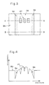
- Fig. 3 illustrates an example of a picture represented by the gray-level image data obtained by imaging the object ob using the image pick-up device 2.
- the picture is displayed on the display unit 4.
- An image OB of part of the object ob is represented on an image BG of the background.
- Images PT of the recognition pattern pt represented on the surface of the object ob also appear.
- Images SH of the shadows sh produced owing to the fact that the object ob is a solid shape appear darker than the surroundings.
- the vertical direction in Fig. 3 corresponds to the longitudinal (height) direction of the cylindrical object ob.
- the images SH of the shadows extend in a band shape along the two sides of the image OB of the object.
- Fig. 4 illustrates the density-level distribution along line A-A of the picture shown in Fig. 3.
- the horizontal axis represents the position along the line A-A
- the vertical axis represents the density level, namely image brightness.
- the portions whose density levels represent the background image BG, shadow images SH and recognition-pattern images PT in Fig. 3 also are indicated using the same characters BG, SH and PT in Fig. 4.
- the line A-A cuts across the location at which the recognition pattern pt exists, and a variation in the density level due to the pattern pt appears on the density-level distribution of Fig. 4 as well.
- the density level of the image OB of the object is high (bright) at the central portion and low (dark) at both sides.
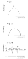
- Fig. 5 illustrates the density-level distribution along line B-B of the picture shown in Fig. 3.
- the line B-B cuts across a location at which the recognition pattern pt is absent. Accordingly, this density-level distribution indicates the distribution of brightness on the surface of the object ob.
- the image OB of the object ob is brightest at the central portion and becomes darker as both sides are approached. The portions on both sides result from the images SH of the shadows. A change in density level due to the recognition pattern pt naturally does not appear.
- Fig. 8 illustrates the operation of the image processing system, and mainly a procedure for shading correction processing executed by the CPU of the image processor 3.
- the object ob is imaged by the image pick-up device 2, the image data representing the object ob is outputted by the image pick-up device 2, and the image data is accepted by the image processor 3 and stored in the image memory (step 101).
- This image data is applied to the display unit 4 so that a picture of the kind shown in Fig. 3 is displayed (step 102).
- the operator designates the horizontal line B-B, which perpendicularly intersects the longitudinal direction of the object ob, on the picture displayed on the display unit 4 (step 103).
- the horizontal line is displayed on the screen of the display unit 4 and the operator determines the height position of the line using the mouse or keyboard of the input unit 5, whereby the line B-B is entered.
- the line B-B is set on the displayed picture at a location that the operator has determined to be one where the images PT of the recognition pattern pt are not present and the density level is uniform in the vertical direction (the density level varies in the transverse direction, as illustrated in Fig. 5).
- the designated line B-B is accepted by the image processor 3, and image data of the portion along the designated line B-B is extracted from the image data that has been stored in the image memory (step 104).
- the density-level distribution represented by the extracted image data is illustrated in Fig. 5. If the amount of image data extracted is one pixel in the vertical direction, this will suffice. It does not matter whether or not this data includes the image data representing the background BG.
- shading-pattern data is produced.
- This shading-pattern data is stored in the image memory (step 105).
- the shading pattern is obtained by expanding, in the vertical direction, the density-level distribution just as it exists along the line B-B.
- the shading pattern represents a two-dimensional distribution of brightness on the surface (excluding the images PT of the recognition pattern) of the object ob.
- An example of this shading pattern is illustrated in Fig. 6. Since the distribution of brightness on the surface of the object ob may be considered to be substantially uniform longitudinally of the object ob with the exception of the portion having the recognition pattern pt, the shading pattern can be produced by simple processing of this kind.
- a shading correction is performed by subtracting the shading-pattern data from the image data obtained as a result of imaging the object ob (step 106).
- the image data obtained by this shading correction processing also is stored in the image memory and is displayed on the display unit 4 (step 107).
- the image data obtained by the shading correction processing represents solely the recognition pattern pt.
- Such image data finally is binarized using an appropriate threshold level.
- the image data long line A-A in Fig. 3 is shown in Fig. 7.
- Portions representing the recognition pattern pt are expressed by level 0, and other portions are expressed by level 1.
- the line B-B was set at the location devoid of the recognition pattern pt on the picture of the object ob.
- the second embodiment is particularly useful in a case where the line for producing the shading pattern cannot be set on a location where no recognition pattern is present.
- Fig. 9 illustrates another example of picture obtained by imaging the cylindrical object using the image pick-up device 2.
- the images PT of the recognition pattern appear across the entire vertical direction of the image. Regardless of how a line is designated in the transverse direction, the line always cuts across the images PT of the recognition pattern.
- Fig. 10 illustrates a density-level distribution along line C-C drawn along the X axis of the image shown in Fig. 9.
- this density-level distribution also, an X-axis brightness distribution on the surface of the object ob appears. The central portion is brightest and the picture grows darker as both sides are approached. Thus, the shadows sh have an influence.
- the background is dark and the density level of the background image BG is low.
- Fig. 14 illustrates the operation of the image processing system, and mainly a procedure for shading correction processing executed by the CPU of the image processor 3.
- the image data representing the object ob imaged by the image pick-up device 2 is accepted by the image processor 3 and stored in the image memory (step 111).
- the picture shown in Fig. 9 represented by this image data is displayed on the display unit 4 (step 112).
- the operator rather than designating a line, designates representative points Q (arbitrary points are acceptable) on vertical lines (except at portions having the images PT of the recognition pattern) deemed to have a uniform brightness along the Y axis of the displayed picture and enters these points from the input unit 5 (step 113). It is desirable that the operator find as many of the vertical lines that seem to have uniform brightness along the Y axis as possible, and that the operator designate and enter as many of the points Q as possible. These points can be designated by moving a cursor on the display screen using the keyboard or mouse.
- Fig. 11 illustrates an example of the brightness distribution thus created.
- Fig. 12 illustrates the distribution of brightness after interpolation.
- Each point Q is a point on a line along the X axis having a uniform distribution along the Y axis, as mentioned above.
- a shading pattern is created by arranging, continuously in the Y direction, the image data representing the distribution of brightness in the X direction shown in Fig. 12 (step 115). This shading pattern is stored in the image memory.
- the shading pattern is a two-dimensional density distribution obtained by expanding the distribution of Fig. 12 in the Y direction as is.
- a shading correction is carried out by subtracting the created shading-pattern data from the image data captured by the image pick-up device 2, or by dividing this image data by the shading-pattern data (step 116).
- the image data obtained by this shading correction processing is stored in the image memory and is displayed on the display unit 4 (step 117).
- Fig. 13 illustrates the density-level distribution represented by the image data along line C-C of Fig. 9. This is the image data that has been subjected to the shading correction.
- This shading processing the influence of the brightness distribution containing the shadows sh on the surface of the object ob is eliminated and the variation in the density level that represents the images PT of the recognition pattern is clearly expressed.
- This image data is binarized as necessary using a threshold level SH.
- an object having a columnar shape is illustrated as the object imaged.
- the invention is applicable also to an object having a prismatic shape (any shape whose cross section is quadrangular, triangular or hexagonal).
- the above-described shading correction can be applied to each portion of equal thickness.
- a third embodiment relates to a method and apparatus capable of performing an accurate shading correction even if the position of an object to be recognized has shifted from the position of the object that served as the basis of shading-pattern creation in the visual field of the image pick-up device.
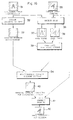
- Fig. 15 is a block diagram illustrating the configuration of an image processing system that includes the shading correction apparatus according to the third embodiment.
- a television camera 11 images an object and outputs a video signal representing the object.
- the video signal is converted into digital image data (gray-level image data) by an A/D converter 12 and the resulting image data is applied to a processing circuit 18 and to a subtracting circuit 22 for shading correction.
- the output image data from the subtracting circuit 22 is converted into an analog signal by a D/A converter 13 and the analog signal is applied to a display unit 14.
- the display unit 14 displays an image of the object imaged by the television camera 11 as well as a created shading pattern or an image resulting from the shading correction.
- the processing circuit 18 generates the shading pattern, executes edge detection processing and binarization processing, etc.
- a positional-offset correcting circuit 16 calculates the amount of positional offset of the image of the object to be recognized relative to a reference image.
- a synchronizing signal generating circuit 15 applies various timing signals to the A/D converter 12, D/A converter 13 and positional-offset correcting circuit 16.
- a CPU 19 supervises the overall operation of image processing inclusive of shading correction processing.
- An input unit 23 is used by the operator to enter various commands, designate the position of a window, etc.
- the image processing system has three image memories. These image memories are a reference-image memory 20 for storing a reference image, a shading master file 17 for storing shading-pattern data that has been created, and an offset-correction shading master file 21 for storing shading-pattern data that has been corrected for positional offset.
- image memories are a reference-image memory 20 for storing a reference image, a shading master file 17 for storing shading-pattern data that has been created, and an offset-correction shading master file 21 for storing shading-pattern data that has been corrected for positional offset.
- the operation of the image processing system roughly comprises pre-processing and shading correction processing.
- the pre-processing includes reference-image registration processing and shading-pattern registration processing. These processing procedures are illustrated in Fig. 16.
- One of a plurality of objects having the same solid shape is selected and photographed by the television camera 11.
- the image of this object is displayed on the display unit 14.
- the image data merely passes through the subtracting circuit 22 without being subjected to the subtraction (shading correction) processing.
- the operator While observing the image displayed on the display unit 14, the operator adjusts the position of the object.
- the operator enters a command from the input unit 23 to register the reference image.
- This command is applied to the CPU 19.
- the latter responds to this command by controlling the processing circuit 18 in such a manner that the image data representing the object entering the processing circuit 18 through the A/D converter 12 is stored in the reference-image memory 20 as reference-image data.
- the data representing the reference image is registered (see reference numeral 31 in Fig. 16).
- the above-mentioned reference position can be decided by the operator at will.
- the position selected is such that the object will be at the center of the visual field of the camera 11 or such that one side of the object will be parallel to one side of the square visual field of the camera 11.
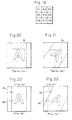
- An example of the registered reference image is illustrated in Fig. 17. Reference characters identical with those of the foregoing embodiments are used for the object, recognition pattern, shadows, etc.
- the image PT of the recognition pattern is the character "A”.
- a line B-B that perpendicularly intersects the longitudinal direction of the object is designated at a location where the image PT of the recognition pattern is absent, as shown in Fig. 17.
- the image data distribution along the line B-B is extracted from the reference-image data that has been stored in the reference-image memory 20 and the distribution is arranged continuously in memory along the longitudinal direction of the object, as a result of which a shading pattern of the kind shown in Fig. 18 is created (see reference numeral 32 in Fig. 16).
- the image data representing the shading pattern created is stored in the shading master file 17 (see reference numeral 33 in Fig. 16).
- a method using a window W instead of the line B-B also is available.
- the CPU 19 responds by controlling the processing circuit 18 so that the circuit 18 generates image data representing the window.
- the image data representing the window is applied to the display unit 14 via the subtracting circuit 22 and D/A converter 13 so that window W is displayed in a form superimposed on the reference image, as shown in Fig. 17 (the display of the line B-B is unnecessary).
- the window W which has a transverse length large enough to include the portions of the shadows SH in the image of the object, perpendicularly intersects the longitudinal direction of the image of the object.
- the operator moves the window W and positions it at a location where the recognition pattern PT is not present.
- the image data within the limits defined by the window W is read out and this data is stored in the shading master file 17.
- the image data within the limits of the window W is arranged, in the shading master file 17, longitudinally of the object in successive widths equivalent to the width of the window W.
- data representing the shading pattern shown in Fig. 18 is created and registered.
- the object to be recognized is placed within the range of the visual field of the camera 11. It does not matter if the position of this object is offset from the position of the object used to create the reference image described above.
- the image of this object is captured by the camera 11 and displayed on the display unit 14 (see reference numeral 35 in Fig. 16). If necessary, the image data obtained by imaging is stored in the image memory. It is assumed that the same recognition pattern (character "A") is represented also on the surface of this object.
- Edge detection processing (inclusive of binarization processing) regarding the reference image stored in the reference-image memory 20 and the image of the object to be recognized (referred to hereinafter as the "target image"), which image has been captured by the camera 11, is executed by the processing circuit 18 (see reference numeral 36 in Fig. 16), and binarized edge images (differentiated images) are obtained (see reference numerals 37, 38 in Fig. 16).
- the edge detection processing is carried out using the operator of a Sobel, by way of example. As shown in Fig. 19, it is assumed that a pixel P 0 is situated at the center, that pixels P 1 , P 2 and P 3 are situated respectively at the upper left, directly above and at the upper right of the center pixel, that pixels P 4 , P 5 are situated respectively at the left and right of the center pixel, and that pixels P 6 , P 7 and P 8 are situated respectively at the lower left, directly below and at the lower right of the center pixel.
- Sobel value (P 0 )
- Equation (1) The operation of Equation (1) is performed with regard to all pixels of the image of the object.
- the Sobel values obtained with regard to all pixels are binarized using an appropriate threshold value.
- edge images are obtained that are represented by one-bit data per pixel, in which data of a pixel representing an edge is 1 while data of other pixels is 0. These edge images are stored in the image memory of the processing circuit 18.
- the amount of positional offset of the target image relative to the reference image is calculated in the positional-offset correcting circuit 16 using the respective edge images of the reference image and target image thus obtained (see reference number 39 in Fig. 16).
- the amount of positional offset is represented by amounts of movement along the X and Y axes and amount of rotation. Though the X and Y axes can be determined arbitrarily, it will suffice to employ axes parallel to the two perpendicular sides of the square visual field of the camera 11.
- the amounts of movement in the X and Y directions are represented by distances in the X and Y directions between a reference point in the reference image and a reference point in the target image.
- reference points can be set on the images PT of these recognition patterns.
- these reference points can be positions of the centers of gravity of the pattern images PT (the characters "A").
- the positions of the centers of gravity serving as reference points can be obtained by setting windows W 1 and W 2 surrounding the characters "A", as shown in Figs. 20 and 21, respectively, extracting the characters "A" within these windows and calculating the centers of gravity thereof.
- Let X 1 , Y 1 represent the coordinate system of the reference image, and let X 2 , Y 2 represent the coordinate system of the target image.
- the amount of rotation can be obtained as the angle of inclination of a straight line appearing in the edge image of the target image with respect to the corresponding straight line appearing in the image of the reference image.
- the straight lines representing the boundaries of the shadows may be used as these straight lines.
- windows W a , W b are set at any two positions astride the edge of a shadow in the edge image of the reference image, and the centers of gravity a (x a ,y a ), b (x b ,y b ) of the image data within the windows W a , W b are obtained. Since the image data is such that the edge is represented by 1 and other portions by 0, the centers of gravity a, b are always on the edge of the shadow.
- windows W c , W d are set at any two positions so as to include the edge of the shadow in the target image, and the centers of gravity c (x c ,y c ), d (x d ,y d ) of the image data within the windows W c , W d are obtained. These centers of gravity c, d also are always on the edge of the shadow.
- the positional-offset correcting circuit 16 reads out shading-pattern data, which has been stored in the shading master file 17, using an address converted in dependence upon the amount of positional offset obtained, and writes this shading-pattern data in the offset-correction shading master file 21 (see reference number 34 in Fig. 16).
- shading-pattern data suitable for a shading correction of the target image having the positional offset relative to the reference image is stored in the offset-correction shading master file 21 (see reference number 40 in Fig. 16).
- a point (x 1 ,y 1 ) in the coordinate system X 1 , Y 1 of the the reference image and the corresponding point (x2, y2) in the coordinate systerr X2, Y2 of the target image are related by the following equation using the above-mentioned coordinates (x1r,y1r), (x2r,y2r) of the reference points and the rotational angle ⁇ .
- the address of the offset-correction shading master file 21 corresponds to the coordinates (x 2 ,y 2 ), and the address of the shading master filter 17 corresponds to the coordinates (x 1 ,y 1 ). Therefore, the write address of the offset-correction shading master file 21 can be converted to the read address of the shading master file 16 by Equations (4) through (7).
- the shading-pattern data that has been corrected for the positional offset is subtracted from the image data of the target image by the subtracting circuit 22 (see reference number 41 in Fig. 16) and the image that has been subjected to the shading correction (see reference numeral 42 in Fig. 16) is displayed on the display unit 14.
- gray-level image data is subjected to processing.
- the invention is applicable also to a color image. Since the color-image data can be separated into R (red), B (blue) and G (green) image data or Y, R-Y and B-Y image data, in which Y serves as luminance data, it will suffice to perform the above-described creation of shading patterns and the shading correction for each of these items of image data.
- the method and apparatus for shading correction according to the present invention is useful in correctly judging characters, figures and the like in a system that images objects and recognizes characters, figures and the like represented on the objects.
Landscapes
- Engineering & Computer Science (AREA)
- Physics & Mathematics (AREA)
- General Physics & Mathematics (AREA)
- Theoretical Computer Science (AREA)
- Computer Graphics (AREA)
- Image Input (AREA)
- Picture Signal Circuits (AREA)
- Facsimile Image Signal Circuits (AREA)
- Character Input (AREA)
- Studio Devices (AREA)
Claims (4)
- Schattierungskorrekturverfahren, bei welchem ein säulenförmiges Objekt (ob) unter Verwendung einer Bildaufnahmevorrichtung (2) zur Gewinnung von das Objekt darstellenden Bilddaten abgebildet und eine Schattierungskorrektur der das Objekt darstellenden Bilddaten unter Verwendung von Schattierungsmusterdaten durchgeführt wird, dadurch gekennzeichnet, daß das Verfahren folgende Schritte aufweist:Anzeigen (Schritt 102) des durch die Bilddaten dargestellten Objektbildes (OB) auf einer Anzeigeeinheit (4);Bezeichnen (Schritt 103), auf dem mit der Anzeigeeinheit angezeigten Objektbild, eines Abtastortes (B-B) in linearer Form über die gesamte Breite des Objekts in einer Richtung senkrecht zur Längsrichtung des Objekts, wobei der Abtastort ein solcher ist, wo keine Bilder (PT), Defekte oder andere verrauschte Bilder vorhanden sind und wo ein Dichtewert als entlang der Längsrichtung auf dem Abtastort gleichförmig beurteilt wird;Herausziehen (Schritt 104) der Bilddaten entlang des bezeichneten Abtastorts zur Bildung einer Referenzdichtewertverteilung;Ausdehnen (Schritt 105) der gebildeten Referenzdichtewertverteilung in der Längsrichtung zur Bildung von Schattierungsmusterdaten, welche die Helligkeitsverteilung auf der Oberfläche des Objekts in zwei Dimensionen darstellt; undDurchführen (Schritt 106) der Schattierungskorrektur der das Objekt darstellenden Bilddaten unter Verwendung der ausgebildeten Schattierungsmusterdaten.
- Schattierungskorrekturverfahren nach Anspruch 1, dadurch gekennzeichnet, daß der Abtastort durch die Lage einer auf dem angezeigten Objektbild gezogenen Linie bezeichnet wird.
- Schattierungskorrekturverfahren nach Anspruch 1, dadurch gekennzeichnet, daß der Abtastort durch ein auf dem Objektbild angezeigtes schlankes Fenster bezeichnet wird.
- Schattierungskorrekturverfahren, bei welchem ein säulenförmiges Objekt (ob) unter Verwendung einer Bildaufnahmevorrichtung (2) zur Gewinnung von das Objekt darstellenden Bilddaten abgebildet und eine Schattierungskorrektur der das Objekt darstellenden Bilddaten unter Verwendung von Schattierungsmusterdaten durchgeführt wird, dadurch gekennzeichnet, daß das Verfahren folgende Schritte aufweist:Anzeigen (Schritt 112) des durch die Bilddaten dargestellten Objektbilds (OB) auf einer Anzeigeeinheit (4);Bezeichnen (Schritt 103) einer Anzahl von repräsentativen Punkten (Q) auf dem mit der Anzeigeeinheit angezeigten Objektbild, wobei die bezeichnete Anzahl von Punkten Punkte auf Linien sind, auf welchen die Dichte als gleichförmig über die gesamte Länge des Objektbilds hinweg betrachtet wird, wobei die Punkte an Abschnitten ohne Bilder (PT), Defekte oder andere verrauschte Bilder liegen und wobei die Punkte so ausgewählt werden, daß eine Referenzdichtewertverteilung über die gesamte Breite des Objektbildes gewonnen wird;Herausziehen (Schritt 114) der Bilddaten an den bezeichneten repräsentativen Punkten und Erzeugen der Referenzdichtewertverteilung durch Anordnen der herausgezogenen Bilddaten der bezeichneten repräsentativen Punkte gemäß einer Koordinatenachse, die eine Längsrichtung des Objekts senkrecht schneidet;Ausdehnen (Schritt 115) der erzeugten Referenzdichtewertverteilung in der Längsrichtung zur Bildung von Schattierungsmusterdaten, welche die Helligkeitsverteilung auf der Oberfläche des Objekts in zwei Dimensionen darstellen; undDurchführen (Schritt 116) der Schattierungskorrektur der das Objekt darstellenden Bilddaten unter Verwendung der gebildeten Schattierungsmusterdaten.
Applications Claiming Priority (3)
| Application Number | Priority Date | Filing Date | Title |
|---|---|---|---|
| JP2407404A JP2893078B2 (ja) | 1990-12-06 | 1990-12-06 | シェーディング補正方法およびその装置 |
| JP407404/90 | 1990-12-06 | ||
| PCT/JP1991/001664 WO1992010810A1 (en) | 1990-12-06 | 1991-11-29 | Method of correcting shading and device therefor |
Publications (3)
| Publication Number | Publication Date |
|---|---|
| EP0568697A1 EP0568697A1 (de) | 1993-11-10 |
| EP0568697A4 EP0568697A4 (en) | 1994-05-18 |
| EP0568697B1 true EP0568697B1 (de) | 1998-07-29 |
Family
ID=18516998
Family Applications (1)
| Application Number | Title | Priority Date | Filing Date |
|---|---|---|---|
| EP91920839A Expired - Lifetime EP0568697B1 (de) | 1990-12-06 | 1991-11-29 | Verfahren zur helligkeitsverbesserung |
Country Status (8)
| Country | Link |
|---|---|
| US (1) | US5621824A (de) |
| EP (1) | EP0568697B1 (de) |
| JP (1) | JP2893078B2 (de) |
| KR (1) | KR970004112B1 (de) |
| AU (1) | AU9021391A (de) |
| CA (1) | CA2097799A1 (de) |
| DE (1) | DE69129908T2 (de) |
| WO (1) | WO1992010810A1 (de) |
Families Citing this family (15)
| Publication number | Priority date | Publication date | Assignee | Title |
|---|---|---|---|---|
| US5732147A (en) * | 1995-06-07 | 1998-03-24 | Agri-Tech, Inc. | Defective object inspection and separation system using image analysis and curvature transformation |
| GB2310557B (en) * | 1996-02-21 | 2000-05-10 | Rank Taylor Hobson Ltd | Image processing apparatus |
| JP3348167B2 (ja) * | 1996-03-26 | 2002-11-20 | シャープ株式会社 | 画像2値化装置 |
| US6192163B1 (en) * | 1996-10-29 | 2001-02-20 | Seiko Epson Corporation | Image processing method and image processing apparatus |
| JPH10222663A (ja) * | 1997-01-31 | 1998-08-21 | Yamaha Motor Co Ltd | 画像認識システム及び装置 |
| US7616198B2 (en) * | 1998-02-20 | 2009-11-10 | Mental Images Gmbh | System and computer-implemented method for modeling the three-dimensional shape of an object by shading of a two-dimensional image of the object |
| JPH11242004A (ja) * | 1997-12-26 | 1999-09-07 | Toshiba Corp | 陰極線管の蛍光面検査方法およびその装置 |
| JP2001186334A (ja) * | 1999-12-27 | 2001-07-06 | Canon Inc | 画像処理装置、画像処理システム、画像処理方法、及び記憶媒体 |
| SG103253A1 (en) | 2000-01-26 | 2004-04-29 | Kent Ridge Digital Labs | Method and apparatus for cancelling lighting variations in object recognition |
| DE10025692A1 (de) * | 2000-05-24 | 2001-11-29 | Abb Patent Gmbh | System zur Darstellung einer Lackschichtdickenverteilung |
| US7391450B2 (en) | 2002-08-16 | 2008-06-24 | Zoran Corporation | Techniques for modifying image field data |
| US7408576B2 (en) * | 2002-08-16 | 2008-08-05 | Zoran Corporation | Techniques for modifying image field data as a function of radius across the image field |
| US7388610B2 (en) * | 2002-08-16 | 2008-06-17 | Zoran Corporation | Techniques of modifying image field data by extrapolation |
| JP4338551B2 (ja) * | 2004-03-04 | 2009-10-07 | 富士フイルム株式会社 | 画像再生方法、画像再生装置及び画像再生プログラム |
| JP4476955B2 (ja) * | 2006-03-17 | 2010-06-09 | 富士通マイクロエレクトロニクス株式会社 | シェーディング補正回路とその制御方法 |
Family Cites Families (14)
| Publication number | Priority date | Publication date | Assignee | Title |
|---|---|---|---|---|
| JPS5213734A (en) * | 1975-07-23 | 1977-02-02 | Hitachi Ltd | Pattern recognition device |
| US4472736A (en) * | 1980-03-11 | 1984-09-18 | Dainippon Ink And Chemicals Incorporated | Lithographic reproduction original classification and color separation tone curve adjustment |
| JPS5823964A (ja) * | 1981-08-05 | 1983-02-12 | 住友化学工業株式会社 | ドライクリ−ニング溶剤の乳化を防止あるいは解消する方法 |
| JPS58223963A (ja) * | 1982-06-22 | 1983-12-26 | Konishiroku Photo Ind Co Ltd | シエ−デイング補正装置 |
| US4747148A (en) * | 1983-04-11 | 1988-05-24 | Kabushiki Kaisha Komatsu Seisakusho | Method of identifying objects |
| US4655349A (en) * | 1984-12-27 | 1987-04-07 | Brockway, Inc. | System for automatically inspecting transparent containers for sidewall and dimensional defects |
| US4679075A (en) * | 1985-04-29 | 1987-07-07 | Emhart Industries, Inc. | Glassware inspection using optical streak detection |
| US4691231A (en) * | 1985-10-01 | 1987-09-01 | Vistech Corporation | Bottle inspection system |
| JPS6376566A (ja) * | 1986-09-19 | 1988-04-06 | Casio Comput Co Ltd | 画像デ−タ読取り装置 |
| DE3641258A1 (de) * | 1986-12-03 | 1988-06-16 | Sick Optik Elektronik Erwin | Bildaufnahmevorrichtung |
| JPH0672770B2 (ja) * | 1988-02-01 | 1994-09-14 | 豊田工機株式会社 | ロボットの物体認識装置 |
| FR2642164B1 (fr) * | 1989-01-26 | 1991-04-12 | Saint Gobain Cinematique Contr | Controle d'objets a forte cadence |
| JPH02217968A (ja) * | 1989-02-18 | 1990-08-30 | Taiyo Eretsukusu Kk | ラベルの検査装置 |
| JPH0736004B2 (ja) * | 1990-09-19 | 1995-04-19 | 肇産業株式会社 | 検査方法及び装置 |
-
1990
- 1990-12-06 JP JP2407404A patent/JP2893078B2/ja not_active Expired - Fee Related
-
1991
- 1991-11-29 KR KR1019930701499A patent/KR970004112B1/ko not_active Expired - Fee Related
- 1991-11-29 US US08/070,360 patent/US5621824A/en not_active Expired - Fee Related
- 1991-11-29 AU AU90213/91A patent/AU9021391A/en not_active Abandoned
- 1991-11-29 DE DE69129908T patent/DE69129908T2/de not_active Expired - Fee Related
- 1991-11-29 CA CA002097799A patent/CA2097799A1/en not_active Abandoned
- 1991-11-29 EP EP91920839A patent/EP0568697B1/de not_active Expired - Lifetime
- 1991-11-29 WO PCT/JP1991/001664 patent/WO1992010810A1/ja not_active Ceased
Also Published As
| Publication number | Publication date |
|---|---|
| US5621824A (en) | 1997-04-15 |
| EP0568697A1 (de) | 1993-11-10 |
| JPH04213169A (ja) | 1992-08-04 |
| DE69129908T2 (de) | 1999-04-29 |
| KR970004112B1 (ko) | 1997-03-25 |
| AU9021391A (en) | 1992-07-08 |
| JP2893078B2 (ja) | 1999-05-17 |
| KR930702725A (ko) | 1993-09-09 |
| WO1992010810A1 (en) | 1992-06-25 |
| EP0568697A4 (en) | 1994-05-18 |
| CA2097799A1 (en) | 1992-06-07 |
| DE69129908D1 (de) | 1998-09-03 |
Similar Documents
| Publication | Publication Date | Title |
|---|---|---|
| EP0568697B1 (de) | Verfahren zur helligkeitsverbesserung | |
| US20090225180A1 (en) | Image processing method and apparatus, digital camera, and recording medium recording image processing program | |
| US7787022B2 (en) | Red-eye filter method and apparatus | |
| US6724945B1 (en) | Correcting defect pixels in a digital image | |
| JPH05236260A (ja) | 画像処理装置 | |
| KR20070008652A (ko) | 촬영된 이미지로부터 원 데이터를 추출하는 방법 | |
| JPH1019731A (ja) | 表示画面検査方法 | |
| WO2010089836A1 (ja) | 画像処理装置 | |
| JP2003167529A (ja) | 画面欠陥検出方法及び装置並びに画面欠陥検出のためのプログラム | |
| US6304672B1 (en) | Edge detecting method and edge detecting device which detects edges for each individual primary color and employs individual color weighting coefficients | |
| US7489832B2 (en) | Imaging apparatus, image processing method for imaging apparatus and recording medium | |
| US6999621B2 (en) | Text discrimination method and related apparatus | |
| US20080018951A1 (en) | Image processing apparatus and control method thereof | |
| JP4662258B2 (ja) | 画像処理方法及び装置、デジタルカメラ装置、並びに画像処理プログラムを記録した記録媒体 | |
| JPH0793535A (ja) | 画像修正処理方法 | |
| JP4852592B2 (ja) | 文字画像補正装置及び文字画像補正方法 | |
| US20070009173A1 (en) | Apparatus and method for shading correction and recording medium therefore | |
| JP3912063B2 (ja) | 画像濃淡ムラの検出方法 | |
| JPH08305785A (ja) | バーコード読み取り装置 | |
| JPH08159984A (ja) | パタンムラ検査装置 | |
| EP1018694B1 (de) | System und Verfahren zur automatischen Graphensyntaxanalyse | |
| JP2001175845A (ja) | 車両端検出装置 | |
| JPH04233402A (ja) | テレビカメラによる対象物の位置認識方式 | |
| JP2513528Y2 (ja) | 濃淡画像処理装置 | |
| JP2005142951A (ja) | 画像読取装置、および画像評価プログラム |
Legal Events
| Date | Code | Title | Description |
|---|---|---|---|
| PUAI | Public reference made under article 153(3) epc to a published international application that has entered the european phase |
Free format text: ORIGINAL CODE: 0009012 |
|
| 17P | Request for examination filed |
Effective date: 19930706 |
|
| AK | Designated contracting states |
Kind code of ref document: A1 Designated state(s): DE FR GB IT |
|
| A4 | Supplementary search report drawn up and despatched | ||
| AK | Designated contracting states |
Kind code of ref document: A4 Designated state(s): DE FR GB IT |
|
| 17Q | First examination report despatched |
Effective date: 19961028 |
|
| GRAG | Despatch of communication of intention to grant |
Free format text: ORIGINAL CODE: EPIDOS AGRA |
|
| GRAG | Despatch of communication of intention to grant |
Free format text: ORIGINAL CODE: EPIDOS AGRA |
|
| GRAG | Despatch of communication of intention to grant |
Free format text: ORIGINAL CODE: EPIDOS AGRA |
|
| GRAH | Despatch of communication of intention to grant a patent |
Free format text: ORIGINAL CODE: EPIDOS IGRA |
|
| GRAH | Despatch of communication of intention to grant a patent |
Free format text: ORIGINAL CODE: EPIDOS IGRA |
|
| GRAA | (expected) grant |
Free format text: ORIGINAL CODE: 0009210 |
|
| AK | Designated contracting states |
Kind code of ref document: B1 Designated state(s): DE FR GB IT |
|
| ITF | It: translation for a ep patent filed | ||
| REF | Corresponds to: |
Ref document number: 69129908 Country of ref document: DE Date of ref document: 19980903 |
|
| ET | Fr: translation filed | ||
| PLBE | No opposition filed within time limit |
Free format text: ORIGINAL CODE: 0009261 |
|
| STAA | Information on the status of an ep patent application or granted ep patent |
Free format text: STATUS: NO OPPOSITION FILED WITHIN TIME LIMIT |
|
| 26N | No opposition filed | ||
| REG | Reference to a national code |
Ref country code: GB Ref legal event code: IF02 |
|
| PGFP | Annual fee paid to national office [announced via postgrant information from national office to epo] |
Ref country code: FR Payment date: 20021119 Year of fee payment: 12 |
|
| PG25 | Lapsed in a contracting state [announced via postgrant information from national office to epo] |
Ref country code: FR Free format text: LAPSE BECAUSE OF NON-PAYMENT OF DUE FEES Effective date: 20040730 |
|
| REG | Reference to a national code |
Ref country code: FR Ref legal event code: ST |
|
| PGFP | Annual fee paid to national office [announced via postgrant information from national office to epo] |
Ref country code: GB Payment date: 20051114 Year of fee payment: 15 |
|
| PG25 | Lapsed in a contracting state [announced via postgrant information from national office to epo] |
Ref country code: IT Free format text: LAPSE BECAUSE OF NON-PAYMENT OF DUE FEES;WARNING: LAPSES OF ITALIAN PATENTS WITH EFFECTIVE DATE BEFORE 2007 MAY HAVE OCCURRED AT ANY TIME BEFORE 2007. THE CORRECT EFFECTIVE DATE MAY BE DIFFERENT FROM THE ONE RECORDED. Effective date: 20051129 |
|
| PGFP | Annual fee paid to national office [announced via postgrant information from national office to epo] |
Ref country code: DE Payment date: 20051130 Year of fee payment: 15 |
|
| PG25 | Lapsed in a contracting state [announced via postgrant information from national office to epo] |
Ref country code: DE Free format text: LAPSE BECAUSE OF NON-PAYMENT OF DUE FEES Effective date: 20070601 |
|
| GBPC | Gb: european patent ceased through non-payment of renewal fee |
Effective date: 20061129 |
|
| PG25 | Lapsed in a contracting state [announced via postgrant information from national office to epo] |
Ref country code: GB Free format text: LAPSE BECAUSE OF NON-PAYMENT OF DUE FEES Effective date: 20061129 |