EP0568751B1 - Vorrichtung zum Treiben von Uhrwerken - Google Patents
Vorrichtung zum Treiben von Uhrwerken Download PDFInfo
- Publication number
- EP0568751B1 EP0568751B1 EP92810324A EP92810324A EP0568751B1 EP 0568751 B1 EP0568751 B1 EP 0568751B1 EP 92810324 A EP92810324 A EP 92810324A EP 92810324 A EP92810324 A EP 92810324A EP 0568751 B1 EP0568751 B1 EP 0568751B1
- Authority
- EP
- European Patent Office
- Prior art keywords
- motors
- rotor
- motor
- rotation
- torque
- Prior art date
- Legal status (The legal status is an assumption and is not a legal conclusion. Google has not performed a legal analysis and makes no representation as to the accuracy of the status listed.)
- Expired - Lifetime
Links
Images


Classifications
-
- G—PHYSICS
- G04—HOROLOGY
- G04C—ELECTROMECHANICAL CLOCKS OR WATCHES
- G04C3/00—Electromechanical clocks or watches independent of other time-pieces and in which the movement is maintained by electric means
- G04C3/14—Electromechanical clocks or watches independent of other time-pieces and in which the movement is maintained by electric means incorporating a stepping motor
- G04C3/146—Electromechanical clocks or watches independent of other time-pieces and in which the movement is maintained by electric means incorporating a stepping motor incorporating two or more stepping motors or rotors
Definitions
- the present invention relates to a drive device for timepieces for rotating the display hands in both directions.
- French patent application No. 79 222 76 describes a two-phase stepper motor comprising a bipolar rotor and two coils arranged obliquely relative to an axis of symmetry, in order to subject the rotor to phase-shifted magnetic fields in space. While this motor offers safe operation in both directions of rotation, it has a relatively low efficiency.
- the efficiency of a watch micromotor depends, on the one hand, on its coil volume, which is generally low due to construction requirements, and on the other hand, on the flux created by the magnet and coupled with the coil.
- the arrangement of pole pieces in this engine implies a surface for the passage of the flux of the magnet limited to the thickness of the stator and over a sector of approximately 120 ° (FIG.
- pole pieces 1a and 1b which has a reduction of approximately 120 ° / 180 °, that is 2/3 compared to the coupled flow in a single-phase motor of the same dimension.
- this two-phase motor has a lower efficiency compared to a single-phase motor of the same dimension.
- the object of the present invention is to remedy these drawbacks by providing a bidirectional drive device having a wide voltage operating range in both directions and a high energy efficiency.
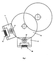
- FIG. 1 schematically shows a first embodiment of the drive device according to the invention.
- the stepping motors 1 and 2 mesh the mobile 3. These motors are arranged so that at rest, in the absence of the currents in the coils 10 and 20, no torque is exerted on the rotors 11 and 21.
- the teeth of the pinions 12 and 22 mounted on the rotors 11 and 21 are oriented at an angle ⁇ relative to the magnetic axis of the rotor magnets, as illustrated in FIG. 5
- This orientation angle ⁇ depends on the number of teeth of the pinions and of the mobile 3, as well as on the relative position of the 2 rotors.
- the angular positions of the rotors at rest are therefore determined only by the positioning notches 13a and 13b, respectively 23a and 23b located on the stator of the motors 1 and 2, as illustrated in FIGS. 2 and 3.
- the axes passing through the positioning notches form with the horizontal axis of the mutual flux between the magnet and the coil the angles ⁇ 1 and ⁇ 2.
- the asymmetrical positions of the magnets at rest give a preferential direction of rotation to each motor. In the example illustrated by Figures 2 and 3, the preferred direction of rotation of the motor 1 is clockwise and that of the motor 2 is counterclockwise. To control the rotation of the mobile 3 in one direction or the other, it suffices to supply either a motor or the other.
- FIG. 6 represents the stator torque laws of the 2 motors as a function of the angle of rotation ⁇ .
- curve 60 represents the positioning torque of each motor taken separately
- curve 61 represents the resulting positioning torque
- curve 62 the torque mutual developed by the motor 1
- curve 63 the mutual torque developed by the motor 2.
- the coil 10 is supplied which supplies the torque 62 to advance the rotor to vicinity of point I. From this moment, the supply of the coil 10 is interrupted and the coil 20 is supplied, since the torque 63 is greater than or equal to the torque 62 from this position.
- FIG. 7 represents the voltage pulses at the terminals of the coils 10 and 20 as a function of time.
- Figure 4 shows a second embodiment of the drive device according to the invention.
- the motors 1 and 2 have a common branch 40 of the stator magnetic circuit, this embodiment making it possible to reduce the total size of the 2 motors. Practical tests have shown that the use of this common branch did not cause any harmful interaction at the level of magnetic fluxes and practically did not create saturation at the level of the magnetic circuit.
Landscapes
- Physics & Mathematics (AREA)
- General Physics & Mathematics (AREA)
- Control Of Stepping Motors (AREA)
- Electromechanical Clocks (AREA)
- Permanent Magnet Type Synchronous Machine (AREA)
Claims (3)
- Vorrichtung zum Treiben von Uhrwerken, mit zwei einphasigen Schrittmotoren (1, 2) die in einen Drehteil (3) eingreifen, wobei jeder Schrittmotor einen statorseitigen Magnetkreis, eine Spule (10, 20) und einen Rotor (11, 21) aus einem Permanentmagneten umfasst, dadurch gekennzeichnet, dass jeder Schrittmotor zum Abgeben einer Rotationsbewegung in einer bevorzugten Drehrichtung eingerichtet ist und dass die bevorzugten Drehrichtungen der beiden Schrittmotoren einander entgegengesetzt sind.
- Vorrichtung nach Anspruch 1, dadurch gekennzeichnet, dass die Schrittmotoren einen Schenkel (40) des statorseitigen Magnetkreises gemeinsam haben.
- Schrittmotor verwendet in der Vorrichtung gemäss den Ansprüchen 1 und 2, dadurch gekennzeichnet, dass die Verzahnung eines Ritzels (12, 22) des Rotors zur magnetischen Achse des Magneten des Rotors ausgerichtet ist.
Priority Applications (3)
| Application Number | Priority Date | Filing Date | Title |
|---|---|---|---|
| EP92810324A EP0568751B1 (de) | 1992-05-04 | 1992-05-04 | Vorrichtung zum Treiben von Uhrwerken |
| DE69201951T DE69201951T2 (de) | 1992-05-04 | 1992-05-04 | Vorrichtung zum Treiben von Uhrwerken. |
| US08/052,627 US5400303A (en) | 1992-05-04 | 1993-04-27 | Driving device for timepieces |
Applications Claiming Priority (1)
| Application Number | Priority Date | Filing Date | Title |
|---|---|---|---|
| EP92810324A EP0568751B1 (de) | 1992-05-04 | 1992-05-04 | Vorrichtung zum Treiben von Uhrwerken |
Publications (2)
| Publication Number | Publication Date |
|---|---|
| EP0568751A1 EP0568751A1 (de) | 1993-11-10 |
| EP0568751B1 true EP0568751B1 (de) | 1995-04-05 |
Family
ID=8211915
Family Applications (1)
| Application Number | Title | Priority Date | Filing Date |
|---|---|---|---|
| EP92810324A Expired - Lifetime EP0568751B1 (de) | 1992-05-04 | 1992-05-04 | Vorrichtung zum Treiben von Uhrwerken |
Country Status (3)
| Country | Link |
|---|---|
| US (1) | US5400303A (de) |
| EP (1) | EP0568751B1 (de) |
| DE (1) | DE69201951T2 (de) |
Families Citing this family (5)
| Publication number | Priority date | Publication date | Assignee | Title |
|---|---|---|---|---|
| US6285745B1 (en) | 1994-12-05 | 2001-09-04 | Bell Atlantic Network Services, Inc. | Analog terminal internet access |
| FR2752496B1 (fr) * | 1996-08-14 | 1998-10-23 | Ebauchesfabrik Eta Ag | Transducteur electromecanique comportant deux rotors a aimants permanents |
| CH690881A5 (fr) * | 1996-12-04 | 2001-02-15 | Ebauchesfabrik Eta Ag | Transducteur électromécanique monophasé et dispositif électromécanique comprenant au moins un tel transducteur. |
| JP2001258227A (ja) * | 2000-01-06 | 2001-09-21 | Seiko Epson Corp | 発電装置、それを有する計時装置および電子機器、発電装置のコギングトルク調整方法 |
| US6932400B2 (en) * | 2003-12-02 | 2005-08-23 | Gwendolyn Gipson | Desktop bible carrying case |
Family Cites Families (3)
| Publication number | Priority date | Publication date | Assignee | Title |
|---|---|---|---|---|
| FR940059A (fr) * | 1947-01-09 | 1948-12-02 | Lepaute Henry S Ets | Réceptrice pour systèmes de distribution d'heure |
| JPS5280063A (en) * | 1975-12-26 | 1977-07-05 | Citizen Watch Co Ltd | Reversible pulse motor system and watch |
| CH653521GA3 (de) * | 1983-09-16 | 1986-01-15 |
-
1992
- 1992-05-04 DE DE69201951T patent/DE69201951T2/de not_active Expired - Fee Related
- 1992-05-04 EP EP92810324A patent/EP0568751B1/de not_active Expired - Lifetime
-
1993
- 1993-04-27 US US08/052,627 patent/US5400303A/en not_active Expired - Fee Related
Also Published As
| Publication number | Publication date |
|---|---|
| DE69201951T2 (de) | 1995-12-21 |
| US5400303A (en) | 1995-03-21 |
| DE69201951D1 (de) | 1995-05-11 |
| EP0568751A1 (de) | 1993-11-10 |
Similar Documents
| Publication | Publication Date | Title |
|---|---|---|
| EP2044490B1 (de) | Elektromechanische hemmungseinrichtung und diese einrichtung benutzender uhrenteil | |
| US6714733B2 (en) | Step motor with interpole pair stabilizing rest position | |
| FR2526993A1 (fr) | Actionneur a mouvement angulaire | |
| EP0746084B1 (de) | Mehrpoliger Zweiläufermotor | |
| EP0568751B1 (de) | Vorrichtung zum Treiben von Uhrwerken | |
| EP0143227B1 (de) | Elektromagnetischen Schrittmotor mit zwei gekuppelten Rotoren | |
| FR2555373A1 (fr) | Alternateur possedant un rotor a aimant permanent et un dispositif de poursuite du fonctionnement en cas de defaillance d'un enroulement statorique | |
| JPS6185055A (ja) | 2方向に回転するステツプモ−タ | |
| EP0509351B1 (de) | Elektromagnetischer Motor mit zwei Drehrichtungen, insbesondere für Zeitmessgerät | |
| KR910008675B1 (ko) | 스테핑 모터를 구비한 전기기계식 시계장치 | |
| JPH06205564A (ja) | 偏心分銅のない振動モータ | |
| EP0393605B1 (de) | Elektronisches Zeitmessgerät mit mindestens zwei Motoren | |
| EP0698957B1 (de) | Electromechanischer Wandler mit zwei Rotoren | |
| JP3411640B2 (ja) | 電磁トランスデューサ | |
| WO2003073599A1 (en) | 2-step bi-directional stepping motor | |
| EP0679970B1 (de) | Mehrphasiger Schrittmotor | |
| EP0790540B1 (de) | Elektromagnetischer Transdukter mit multipolaren Permanentmagneten | |
| CH690881A5 (fr) | Transducteur électromécanique monophasé et dispositif électromécanique comprenant au moins un tel transducteur. | |
| EP0848480B1 (de) | Einphase elektromechanischer Wandler und elektromechanische Einrichtung mit wenigstens einem solchen Wandler | |
| LT3558B (en) | A multipole step by step machine | |
| EP4650885A1 (de) | Schrittmotorsteuerungsvorrichtung für eine elektronische uhr | |
| CH620331B (de) | Einphasenschrittmotor. | |
| CH691016A5 (fr) | Moteur pas à pas à rotors multiples. | |
| JPH08182299A (ja) | 回転磁界型モータ | |
| JPS57153557A (en) | Miniature motor for timepiece |
Legal Events
| Date | Code | Title | Description |
|---|---|---|---|
| PUAI | Public reference made under article 153(3) epc to a published international application that has entered the european phase |
Free format text: ORIGINAL CODE: 0009012 |
|
| AK | Designated contracting states |
Kind code of ref document: A1 Designated state(s): AT BE CH DE DK ES FR GB GR IT LI LU MC NL PT SE |
|
| RBV | Designated contracting states (corrected) |
Designated state(s): CH DE FR GB IT LI NL |
|
| 17P | Request for examination filed |
Effective date: 19940413 |
|
| 17Q | First examination report despatched |
Effective date: 19940809 |
|
| GRAA | (expected) grant |
Free format text: ORIGINAL CODE: 0009210 |
|
| AK | Designated contracting states |
Kind code of ref document: B1 Designated state(s): CH DE FR GB IT LI NL |
|
| REF | Corresponds to: |
Ref document number: 69201951 Country of ref document: DE Date of ref document: 19950511 |
|
| ITF | It: translation for a ep patent filed | ||
| GBT | Gb: translation of ep patent filed (gb section 77(6)(a)/1977) |
Effective date: 19950626 |
|
| PLBE | No opposition filed within time limit |
Free format text: ORIGINAL CODE: 0009261 |
|
| 26N | No opposition filed | ||
| PGFP | Annual fee paid to national office [announced via postgrant information from national office to epo] |
Ref country code: FR Payment date: 19990412 Year of fee payment: 8 |
|
| PGFP | Annual fee paid to national office [announced via postgrant information from national office to epo] |
Ref country code: GB Payment date: 19990420 Year of fee payment: 8 |
|
| PGFP | Annual fee paid to national office [announced via postgrant information from national office to epo] |
Ref country code: DE Payment date: 19990426 Year of fee payment: 8 |
|
| PGFP | Annual fee paid to national office [announced via postgrant information from national office to epo] |
Ref country code: NL Payment date: 19990427 Year of fee payment: 9 |
|
| PG25 | Lapsed in a contracting state [announced via postgrant information from national office to epo] |
Ref country code: GB Free format text: LAPSE BECAUSE OF NON-PAYMENT OF DUE FEES Effective date: 20000504 |
|
| PG25 | Lapsed in a contracting state [announced via postgrant information from national office to epo] |
Ref country code: NL Free format text: LAPSE BECAUSE OF NON-PAYMENT OF DUE FEES Effective date: 20001201 |
|
| GBPC | Gb: european patent ceased through non-payment of renewal fee |
Effective date: 20000504 |
|
| PG25 | Lapsed in a contracting state [announced via postgrant information from national office to epo] |
Ref country code: FR Free format text: LAPSE BECAUSE OF NON-PAYMENT OF DUE FEES Effective date: 20010131 |
|
| NLV4 | Nl: lapsed or anulled due to non-payment of the annual fee |
Effective date: 20001201 |
|
| PG25 | Lapsed in a contracting state [announced via postgrant information from national office to epo] |
Ref country code: DE Free format text: LAPSE BECAUSE OF NON-PAYMENT OF DUE FEES Effective date: 20010301 |
|
| REG | Reference to a national code |
Ref country code: FR Ref legal event code: ST |
|
| PG25 | Lapsed in a contracting state [announced via postgrant information from national office to epo] |
Ref country code: IT Free format text: LAPSE BECAUSE OF NON-PAYMENT OF DUE FEES;WARNING: LAPSES OF ITALIAN PATENTS WITH EFFECTIVE DATE BEFORE 2007 MAY HAVE OCCURRED AT ANY TIME BEFORE 2007. THE CORRECT EFFECTIVE DATE MAY BE DIFFERENT FROM THE ONE RECORDED. Effective date: 20050504 |
|
| REG | Reference to a national code |
Ref country code: CH Ref legal event code: PFA Free format text: DETRA S.A.; 35, RUE SCHOLL; 2504 BIEL/BIENNE (CH) -TRANSFER TO- DETRA SA; RUE DU CORNOUILLER 4; CH-2502 BIENNE (CH) |
|
| REG | Reference to a national code |
Ref country code: CH Ref legal event code: NV Representative=s name: WILLIAM BLANC & CIE CONSEILS EN PROPRIETE INDUSTRI |
|
| REG | Reference to a national code |
Ref country code: CH Ref legal event code: PFA Owner name: DETRA SA Free format text: DETRA SA#RUE DU CORNOUILLER 4#CH-2502 BIENNE (CH) -TRANSFER TO- DETRA SA#RUE DU CORNOUILLER 4#CH-2502 BIENNE (CH) |
|
| PGFP | Annual fee paid to national office [announced via postgrant information from national office to epo] |
Ref country code: CH Payment date: 20100427 Year of fee payment: 19 |
|
| REG | Reference to a national code |
Ref country code: CH Ref legal event code: PCAR Free format text: NOVAGRAAF SWITZERLAND SA;CHEMIN DE L'ECHO 3;1213 ONEX (CH) |
|
| REG | Reference to a national code |
Ref country code: CH Ref legal event code: PL |
|
| PG25 | Lapsed in a contracting state [announced via postgrant information from national office to epo] |
Ref country code: LI Free format text: LAPSE BECAUSE OF NON-PAYMENT OF DUE FEES Effective date: 20110531 Ref country code: CH Free format text: LAPSE BECAUSE OF NON-PAYMENT OF DUE FEES Effective date: 20110531 |