EP0568936A1 - Flüssigkeitströpfchen-Erzeuger - Google Patents
Flüssigkeitströpfchen-Erzeuger Download PDFInfo
- Publication number
- EP0568936A1 EP0568936A1 EP93107059A EP93107059A EP0568936A1 EP 0568936 A1 EP0568936 A1 EP 0568936A1 EP 93107059 A EP93107059 A EP 93107059A EP 93107059 A EP93107059 A EP 93107059A EP 0568936 A1 EP0568936 A1 EP 0568936A1
- Authority
- EP
- European Patent Office
- Prior art keywords
- fluid
- housing
- piston
- manifold
- transducer
- Prior art date
- Legal status (The legal status is an assumption and is not a legal conclusion. Google has not performed a legal analysis and makes no representation as to the accuracy of the status listed.)
- Granted
Links
Images


Classifications
-
- B—PERFORMING OPERATIONS; TRANSPORTING
- B05—SPRAYING OR ATOMISING IN GENERAL; APPLYING FLUENT MATERIALS TO SURFACES, IN GENERAL
- B05B—SPRAYING APPARATUS; ATOMISING APPARATUS; NOZZLES
- B05B17/00—Apparatus for spraying or atomising liquids or other fluent materials, not covered by the preceding groups
- B05B17/04—Apparatus for spraying or atomising liquids or other fluent materials, not covered by the preceding groups operating with special methods
- B05B17/06—Apparatus for spraying or atomising liquids or other fluent materials, not covered by the preceding groups operating with special methods using ultrasonic or other kinds of vibrations
- B05B17/0607—Apparatus for spraying or atomising liquids or other fluent materials, not covered by the preceding groups operating with special methods using ultrasonic or other kinds of vibrations generated by electrical means, e.g. piezoelectric transducers
Definitions
- the present invention relates to a liquid droplet generator and, more particularly, to a high energy, acoustic droplet generator capable of creating high amplitude velocity perturbations on a stream of fluid which are sufficient to atomize the fluid into a stream of droplets.
- the atomization of a jet or sheet of liquid is a process which, in most cases, requires energy to be added to the liquid.
- the added energy is converted into an increase in surface energy in the liquid as the initial liquid mass is separated into droplets.
- the surface area of the liquid likewise increases.
- Energy may be supplied for purposes of atomization from either a decrease in kinetic energy of the liquid or from an external source.
- One prior art process for atomizing a fluid involves impinging a fast moving air stream onto a slower moving fluid, such as a fuel to be burned in a combustor of a turbine engine. With this process, the kinetic energy of the injected air serves to tear the liquid into filaments and then into drops. Thus, a portion of the kinetic energy of the injected air is converted into an increase in surface energy in the atomized fluid.
- the prior art air injection process when used to atomize a fuel to be burned in a turbine engine, is only effective when the engine is operating, since a source of high velocity air is needed for atomization. Further, higher engine operating temperatures, which result in greater engine operating efficiency, are difficult to achieve since excess air is added into the engine for purposes of atomization. Additionally atomization by use of injected air results in an inconsistent distribution of fuel spray in both time and space. As a result, the combustor is required to be longer than otherwise necessary to ensure that all the fuel is burned before the air/fuel mixture exits the combustor. The inconsistent distribution of fuel spray also results in a non-uniform combustion of the air/fuel mixture causing an increase in NOx pollutants being emitted from the engine.
- a further prior art atomization process involves the acoustic excitation of a circular liquid jet at an unstable wavelength.
- Rayleigh explained in 1878 that a circular fluid jet is unstable for azimuthally symmetric perturbations whose axial wavelength is longer than the circumference of the jet.
- This prior art process is based upon Rayleigh's theoretical work. The process involves placing small amplitude acoustic perturbations on a circular jet, wherein the perturbations have a wavelength longer than the circumference of the jet.
- the applied perturbations grow, due to an input of energy from surface tension, and break the jet into a stream of drops at the excitation frequency. This process adds little or no energy to the fluid.
- the surface area and surface energy of the fluid is lower after break-up than before.
- the size of the resulting drops produced by this process have a diameter approximately twice the diameter of the original jet.
- small nozzles or orifices must be used.
- Small nozzles can be easily obstructed by particles carried by a fluid. Consequently, this process is disadvantageous for use where small droplets are desired. Further, this process will not induce atomization of a sheet of liquid.
- an apparatus which is capable of adding energy to a liquid stream for purpose of atomization without employing high velocity air.
- a high energy, acoustic droplet generator for imparting energy into a stream of liquid in the form of velocity perturbations for purposes of atomizing the fluid into a stream of droplets. Because energy is added to the liquid stream, the surface area of the surface energy of the resulting stream of droplets is greater than that of the initial liquid stream.
- a droplet generator for breaking a fluid jet into a stream of droplets.
- the droplet generator comprises a housing having a first end, a second end, and an inner cavity.
- the second end of the housing has at least one orifice therein.
- An acoustic transducer is connected to the housing and has a first portion located within the cavity and spaced a given distance from the second end of the housing.
- the first portion of the acoustic transducer and the second end of the housing define a manifold therebetween for receiving a fluid.
- Fluid supply means are connected to either the housing or the acoustic transducer for supplying fluid under pressure to the inner cavity and into the manifold.
- the fluid passes from the manifold via the orifice as a stream of fluid.
- Drive means are provided for driving the transducer and causing the first portion of the transducer to impart acoustic energy to the fluid in the manifold, thereby creating velocity perturbations on the stream of fluid which are sufficient to atomize the fluid.
- the acoustic transducer preferably comprises: a mount fixedly connected to the first end of the housing; a piston which defines the first portion of the transducer; piezoelectric means positioned between the mount and the piston for causing the piston to oscillate relative to the second end of the housing and impart acoustic energy to the fluid in the manifold; and, connector means for connecting the mount, the piston and the piezoelectric means to one another. Further provided is sealing means for sealing the piston to the housing and thereby forming a sealed chamber for receiving the fluid. At least a portion of the piston is positioned within the chamber and a section of the chamber is defined by the manifold.
- the piezoelectric means may comprise at least two piezoelectric crystals.
- the mount includes a centrally located stepped bore.
- Each of the piezoelectric crystals includes a centrally located bore extending therethrough, while the piston includes a centrally located threaded bore which extends at least partially therethrough.
- the connector means may comprise a bolt which extends through the bores in the mount and the piezoelectric crystals and threadedly engages with the threaded bore in the piston for connecting the mount, the piezoelectric crystals, and the piston to one another.
- the bolt preferably includes a centrally located passage extending therethrough.
- the piston includes at least one additional bore extending from an outer surface thereof to communicate with the centrally located passage extending through the bolt.
- the fluid supply means communicates with the passage in the bolt for supplying fluid through the passage and the at least one additional bore in the piston to the cavity and into the manifold.
- the drive means serves to drive the transducer at a natural frequency of the transducer. This causes large amplitude oscillations of the first portion of the transducer, thereby resulting in the first portion of the transducer imparting acoustic energy to the fluid in the manifold which results in large amplitude velocity perturbations on the stream of fluid.
- the housing includes a hollow main portion having first and second ends.
- the first end of the main portion defines the first end of the housing.
- a nozzle plate is connected to the second end of the hollow main portion.
- the nozzle plate defines the second end of the housing and has the at least one orifice formed therein.
- the housing comprises a hollow main portion having first and second ends.
- the first end of the main portion defines the first end of the housing.
- An intermediate nozzle plate support is connected to the second end of the hollow main portion.
- a nozzle plate is connected to the nozzle plate support and has the one orifice formed therein. The nozzle plate and the intermediate plate define the second end of the housing.
- a method for generating droplets from a stream of liquid.
- the method comprises the steps of: providing a housing having a first end, a second end, and an inner cavity, the second end having at least one orifice; providing an acoustic transducer having a first portion located within the cavity and spaced a given distance from the second end of the housing, the first portion of the acoustic transducer and the second end of the housing defining a manifold therebetween for receiving a fluid; supplying fluid under pressure to the inner cavity and into the manifold, the fluid passing from the manifold via the orifice as a stream of fluid; and, driving the acoustic transducer and causing the first portion of the acoustic transducer to impart acoustic energy to the fluid in the manifold, thereby creating velocity perturbations on the stream of fluid which are sufficient to atomize the fluid.
- the step of providing an acoustic transducer comprises the steps of: fixedly connecting a mount to the first end of the housing; providing a piston to define the first portion of the transducer; positioning piezoelectric means between the mount and the piston for causing the piston to oscillate relative to the second end of the housing and impart acoustic energy to the fluid in the manifold; and, connecting the mount, the piston and the piezoelectric means to one another.
- the piezoelectric means may comprise at least two piezoelectric crystals.
- the mount, the piezoelectric crystals, and the piston include bores as discussed above with regard to the first aspect of the present invention.
- the step of connecting the mount, the piston and the piezoelectric means to one another is performed by passing a bolt through the bores in the mount and the piezoelectric crystals and threadedly engaging the bolt with the bore in the piston for connecting the piezoelectric crystals, the mount and the piston to one another.
- the bolt includes a centrally located passage extending therethrough.
- the piston includes an additional bore extending from an outer surface of the piston to communicate with the centrally located passage extending through the bolt.
- the step of supplying fluid to the inner cavity and into the manifold is performed by passing fluid through the passage in the bolt and the additional bore in the piston to the cavity and into the manifold.
- the step of driving the transducer is performed at a natural frequency thereof causing large amplitude oscillations of the first portion of the transducer, thereby resulting in the first portion imparting acoustic energy to the fluid in the manifold which results in large amplitude velocity perturbations on the stream of fluid.
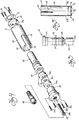
- a droplet generator constructed in accordance with the present invention is shown in Figures 1 and 2, and is generally designated by the reference numeral 10.
- the droplet generator 10 includes a housing 20 having a substantially cylindrical main body portion 22 and an exit portion 24. Upper end 22a of the main body portion 22 defines a first end of the housing 20 and exit portion 24 defines a second end of the housing 20.
- Connected to the main body portion 22 of the housing 20 is an acoustic transducer 30.
- the transducer 30 includes a piston 32 (also referred to herein as a first portion of the transducer) located within an inner cavity 26 of the housing and spaced a given distance (e.g., between .010 in.
- the piston 32 and the entrance surface 24a define a manifold 40 therebetween for receiving a fluid.
- Drive means 50 is connected to the transducer 30 for driving the transducer 30 and causing the piston 32 to impart acoustic energy to the fluid in the manifold 40, thereby creating high amplitude velocity perturbations on the outgoing stream of fluid which are sufficient to atomize the fluid into a stream of droplets 60, as shown in Figure 1. Because energy is added to the stream of droplets 60, the surface area and the surface energy of the droplets 60 is greater than that of the initial liquid mass from which the droplets are formed.
- a fluid supply 62 communicates with the acoustic transducer 30 through a fluid supply line 64 for providing pressurized fluid to the transducer 30.
- the fluid supplied to the transducer 30 passes from the transducer 30 into the inner cavity 26 and into the manifold 40.
- the fluid exits from the generator 10 via orifices or nozzles 70 formed within a nozzle plate 72, which comprises a first section of the exit portion 24 of the housing 20.
- the orifices 70 are formed in the plate 72 as a linear array of spaced apart circular openings (see Figure 7),
- the acoustic transducer 30 includes a mount 33 fixedly connected to the main body portion 22 of the housing 20 via bolts 33a. Positioned between the mount 33 and the piston 32 are two piezoelectric crystals 34 having an electrode 35 interposed therebetween. The electrode 35 extends through a slot 28 in the main body portion 22 for connecting with the drive means 50, as illustrated in Figure 1.
- the drive means serves to drive the transducer 30 for causing the piston 32 to oscillate relative to the exit portion 24 of the housing 20 and impart acoustic energy to the fluid in the manifold 40 to atomize the fluid.
- a bolt 38 (also referred to herein as connector means) is provided for connecting the piston 32, the mount 33, the piezoelectric crystals 34, and the electrode 35 to one another to form the transducer 30.
- the bolt 38 passes through a centrally located stepped bore 33b in the mount 33, a centrally located bore 34a in each of the piezoelectric crystals 34 and a bore 35a located in the electrode 35.
- the upper portion 38a of the bolt 38 seats in the stepped bore 33b in the mount 33, while the lower portion 38b threadedly engages with a centrally located threaded bore 32a in the piston 32.
- the transducer 30 further includes sealing means comprising an O-ring 39 for sealing the piston 32 to the main body portion 22 of the housing 20 and thereby forming a sealed chamber 42 for receiving the fluid. At least a portion of the piston 32 is positioned within the chamber 42 and a section of the chamber 42 is defined by the manifold 40.
- the bolt 38 includes a centrally located passage 38c extending therethrough, as shown in dotted line in Figure 2.
- the piston 32 includes an additional bore 32b extending from an outer surface 32c of the piston 32 for communicating with the centrally located passage 38c extending through the bolt 38.
- the fluid supply line 64 is connected to the mount 33 via connector 65 and communicates with the passage 38c in the bolt 38 for supplying fluid through the passage 38c and the additional bore 32b in the piston 32 to the sealed chamber 42 and into the manifold 40.
- the fluid supply means 62 preferably supplies fluid through line 64 at a pressure between 10-60 psi.
- a nozzle support plate 74 is interposed between the nozzle plate 72 and the main body portion 22 of the housing 20.
- the support plate 74 comprises a second section of the exit portion 24 of the housing 20 and its upper surface defines the entrance surface 24a of the exit portion 24 of the housing 20.
- the nozzle support plate 74 includes a centrally located opening 74a through which the fluid passes before it exits through the orifices 70 in the nozzle plate 72.
- Bolts 76 pass through corresponding openings in the plates 72 and 74 and threadedly engage with corresponding openings 22b found in the main body portion 22 of the housing 20 to secure the plates 72 and 74 to the main body portion 22.
- Adhesive (not shown), such as an epoxy, may be interposed between the nozzle support plate 74 and the nozzle plate 72 for further securing and sealing the nozzle plate 72 to the nozzle support plate 74.
- the nozzle support plate 74 acts to increase the rigidity of the nozzle plate 72.
- a more rigid nozzle plate 72 allows for a more efficient conversion of the oscillatory effects of the piston 32 to fully periodically compress the fluid thereby forming pressure perturbations in the fluid within the manifold 40.
- the nozzle plate 72 may alternatively be attached directly to the main body portion 22 of the housing 20 via bolts 76.
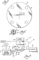
- the drive means 50 preferably comprises the driving circuit 52 shown in Figure 8, and disclosed in U.S. Patent No. 3,868,698 (entitled “Stimulation Control Apparatus for an Ink Jet Recorder,” issued February 25, 1975), the disclosure of which is incorporated herein by reference.
- the driving circuit includes a differential amplifier 53, a power amplifier 54, a load resistor 55, and negative and positive feedback loops to the negative and positive input terminals 53a and 53b of the differential amplifier 53.
- the negative feedback loop extends from output terminal 53c of differential amplifier 53 back around to the negative input terminal 53a.
- the negative feedback loop therefore includes load resistor 55 and branches out into two branches at the output side thereof.
- One of these two negative branches includes only a resistor 56, whereas the other branch comprises a peak detector 57a, a differential amplifier 57b and a voltage dependent resistance 57c.
- the positive feedback loop extends from output terminal 53c back through an R-C network to the positive input terminal 53b.
- the positive feedback loop comprises resistors 58a and 58b and capacitors 59a and 59b connected in a wien bridge arrangement.
- the circuit 52 serves to drive the transducer 30 at a natural frequency thereof and to track that frequency as it changes normally due to heating or other causes during operation of the droplet generator 10.
- the transducer 30 normally has more than one natural frequency. Consequently, it is usually possible to drive the piezoelectric crystals 34 at more than one frequency. Additionally, several frequencies may be placed on the crystals 34 at the same time.
- the amplitude of motion of the bottom surface 32d of the piston 32 is much greater than the amplitude of motion of the crystals 34 combined. Consequently, the oscillating bottom surface 32d of the piston 32 imparts sufficient acoustic energy to the fluid in the manifold 40 to create large amplitude velocity perturbations on the fluid which result in atomization of the fluid into a stream of droplets.
- a nozzle plate 80 constructed in accordance with a second embodiment of the present invention.
- the nozzle plate 80 is formed having a nozzle 82 through which fluid in the manifold 40 exits from the droplet generator 10.
- the plate 80 may be formed according to the process disclosed in U.S. Patent No. 4,528,070, the disclosure of which is incorporated herein by reference.
- the plate 80 comprises first and second layers of nickel 84 and 86, respectively, and an intermediate layer of beryllium-copper 88 interposed therebetween, see Figures 11A and 11B.
- the first layer 84 is formed with an entrance slot 84a through which the fluid first passes as it exits from the manifold 40.
- the second layer 86 is formed with an exit slot 86a through which the fluid exits from the generator 10 after passing through the entrance slot 84a.
- the entrance slot 84a is rotated from the exit slot 86a at an angle ⁇ , which is approximately 4°.
- the entrance slot 84a has a length of approximately .220 in. and a width of approximately .006 in.
- the exit slot 86a has a length of approximately .210 in. and a width of approximately .0015 in.
- the thickness of the plate 80 including the first, second and intermediate layers 84, 86 and 88, respectively, is approximately .010 in.
- a stream of droplets formed by a droplet generator 10 according to the present invention employing the nozzle plate 80 is shown in the photograph of figure 12.
- the droplet generator 10 included a nozzle support plate 74 having a thickness of approximately .25 in.
- the fluid supplied to the generator 10 comprised a formulation of water to glycerol in a weight ratio of 4:6.
- the fluid was supplied to the generator 10 at a pressure of approximately 33.6 psi.
- the drop generator transducer 30 was driven at a frequency of approximately 9.78 kHz, which was approximately equal to a natural frequency of the transducer 30.
- the fluid as it exits from the generator 10, first breaks into a plurality of horizontal filaments and then into a plurality of droplets.
- the nozzle plate 90 includes a nozzle 92 through which fluid in the manifold 40 exits from the droplet generator 10.
- the nozzle plate 90 may be formed according to the process disclosed in U.S. Patent No. 4,528,070.
- the nozzle plate 90 includes first and second layers of nickel 94 and 96, respectively, and an intermediate layer of beryllium-copper 98 interposed therebetween, see Figure 14.
- the first layer 94 is formed with an entrance slot 94a through which the fluid first passes as it exits from the manifold 40.
- the second layer 96 is formed with an exit slot 97 through which the fluid exits from the generator 10 after passing through the entrance slot 94a.
- the entrance slot 94a is rotated from the exit slot 97 at an angle ⁇ (shown exaggerated in Figure 13), which is approximately 3.4°.
- the entrance slot 94a has a length of approximately .210 in. and a width of approximately .006 in.
- the exit slot 97 is formed with a plurality of perturbations 97a, each having a length L1 equal to approximately .040 in.
- the exit slot 97 has a length of approximately .240 in. and has a first width W1 equal to .003 in. and a second width W2 equal to .0015 in.
- the thickness of the plate 90 including the first, second and intermediate layers 94, 96 and 98, respectively, is approximately .010 in
- a stream of droplets formed by a droplet generator 10 according to the present invention employing the nozzle plate 90 is shown in the photograph of Figure 15.
- the droplet generator 10 included a nozzle support plate 74 having a thickness of approximately .25 in.
- the fluid supplied to the generator 10 comprised a formulation of water to glycerol in a weight ratio of 4:6.
- the fluid was supplied to the generator 10 at a pressure of approximately 33.6 psi.
- the drop generator transducer 30 was driven at a frequency of approximately 5.55 kHz, which was approximately equal to a natural frequency of the transducer 30.
- As shown in the photograph as the fluid sheet exits from the generator 10, it breaks into horizontal filaments and then into a plurality of droplets.
- the nozzle plate 100 includes a nozzle 102 through which fluid in the manifold 40 exits from the droplet generator 10.
- the plate 100 may be formed according to the process disclosed in U.S. Patent No. 4,528,070.
- the plate 100 includes first and second layers of nickel 104 and 106, respectively, and an intermediate layer of beryllium-copper 108 interposed therebetween, see Figure 17.
- the first layer 104 is formed with an entrance slot 104a through which the fluid first passes as it exits from the manifold 40.
- the second layer 106 is formed with an exit slot 107 through which the fluid exits from.
- the entrance slot 104a has a length of approximately .210 in. and a width of approximately .0015 in.
- the exit slot 107 includes a plurality of perturbations 107a, each having a length L a equal to .010 in.
- the exit slot 107 has a length of approximately .210 in. and a first width W a approximately equal to .002 in. and a second width W b approximately equal to .0015 in.
- the entrance slot 104a is offset from the exit slot 107 by a distance D which is approximately equal to .001 in.
- the thickness of the plate 100 including the first, second and intermediate layers 104, 106 and 108, respectively, is approximately .010 in.
- a stream of droplets formed by a droplet generator 10 according to the present invention employing the nozzle plate 100 is shown in the photograph of Figure 18.
- the droplet generator 10 included a nozzle support plate 74 having a thickness of approximately .25 in.
- the fluid supplied to the generator 10 comprised a formulation of water to glycerol in a weight ratio of 4:6.
- the fluid was supplied to the generator 10 at a pressure of approximately 33.6 psi.
- the drop generator transducer 30 was driven at a frequency of approximately 9.64 kHz, which is approximately equal to a natural frequency of the transducer 30.
- the fluid breaks into a plurality of droplets as it exits from the nozzle 102 at an angle from vertical.
- a method and apparatus are provided for imparting energy into a stream of liquid in the form of velocity perturbations for purposes of atomizing the liquid into a stream of droplets. Because energy is imparted into the stream of liquid, the liquid atomizes into a stream of droplets having a surface area and surface energy greater than that of the initial stream.
- droplet generator 10 of the present application may be employed in applications such as agricultural spraying, spray drying and fuel injection.
- the transducer 30 may be driven with a high voltage so as to create large amplitude oscillations of the piston 32. It is additionally contemplated that several piezoelectric crystal pairs can be employed, and each pair may be driven at a different frequency.
Landscapes
- Special Spraying Apparatus (AREA)
- Fuel-Injection Apparatus (AREA)
Applications Claiming Priority (2)
| Application Number | Priority Date | Filing Date | Title |
|---|---|---|---|
| US880890 | 1992-05-08 | ||
| US07/880,890 US5248087A (en) | 1992-05-08 | 1992-05-08 | Liquid droplet generator |
Publications (2)
| Publication Number | Publication Date |
|---|---|
| EP0568936A1 true EP0568936A1 (de) | 1993-11-10 |
| EP0568936B1 EP0568936B1 (de) | 1998-09-16 |
Family
ID=25377341
Family Applications (1)
| Application Number | Title | Priority Date | Filing Date |
|---|---|---|---|
| EP93107059A Expired - Lifetime EP0568936B1 (de) | 1992-05-08 | 1993-04-30 | Flüssigkeitströpfchen-Erzeuger |
Country Status (4)
| Country | Link |
|---|---|
| US (1) | US5248087A (de) |
| EP (1) | EP0568936B1 (de) |
| JP (1) | JP3345459B2 (de) |
| DE (1) | DE69321025T2 (de) |
Cited By (2)
| Publication number | Priority date | Publication date | Assignee | Title |
|---|---|---|---|---|
| US5628937A (en) * | 1992-12-18 | 1997-05-13 | Imperial Chemical Industries Plc | Production of particulate materials |
| WO2017046607A1 (en) * | 2015-09-17 | 2017-03-23 | The James Hutton Institute | Atomiser assembly |
Families Citing this family (58)
| Publication number | Priority date | Publication date | Assignee | Title |
|---|---|---|---|---|
| US7628339B2 (en) | 1991-04-24 | 2009-12-08 | Novartis Pharma Ag | Systems and methods for controlling fluid feed to an aerosol generator |
| US6540154B1 (en) | 1991-04-24 | 2003-04-01 | Aerogen, Inc. | Systems and methods for controlling fluid feed to an aerosol generator |
| WO1996008373A1 (en) * | 1994-09-16 | 1996-03-21 | Videojet Systems International, Inc. | Continuous ink jet printing system for use with hot-melt inks |
| US5560543A (en) * | 1994-09-19 | 1996-10-01 | Board Of Regents, The University Of Texas System | Heat-resistant broad-bandwidth liquid droplet generators |
| US6085740A (en) | 1996-02-21 | 2000-07-11 | Aerogen, Inc. | Liquid dispensing apparatus and methods |
| US5758637A (en) | 1995-08-31 | 1998-06-02 | Aerogen, Inc. | Liquid dispensing apparatus and methods |
| US5618902A (en) * | 1995-11-03 | 1997-04-08 | General Electric Company | Vapor precipitation of polymers from solvent polymer blends by azeotropic spray drying |
| SE507519C2 (sv) * | 1996-10-16 | 1998-06-15 | Mydata Automation Ab | Anordning för att anbringa ett visköst medium på ett underlag |
| US5855323A (en) * | 1996-11-13 | 1999-01-05 | Sandia Corporation | Method and apparatus for jetting, manufacturing and attaching uniform solder balls |
| SE513527C2 (sv) * | 1998-06-11 | 2000-09-25 | Mydata Automation Ab | Anordning och förfarande för utskjutning av små droppar |
| US6135357A (en) * | 1998-11-23 | 2000-10-24 | General Electric Company | Apparatus for atomizing high-viscosity fluids |
| DE19905413A1 (de) | 1999-02-10 | 2000-08-24 | Bosch Gmbh Robert | Injektor mit Piezo-Mehrlagenaktor für Einspritzsysteme |
| US6702196B2 (en) | 1999-03-31 | 2004-03-09 | Ngk Insulators, Ltd. | Circuit for driving liquid drop spraying apparatus |
| WO2000060238A1 (fr) * | 1999-03-31 | 2000-10-12 | Ngk Insulators, Ltd. | Commande de pulverisateur et circuit a cet effet |
| FR2795348B1 (fr) * | 1999-06-22 | 2001-09-14 | Osmooze Sa | Dispositif programmable de diffusion de pics d'odeurs |
| US6235177B1 (en) | 1999-09-09 | 2001-05-22 | Aerogen, Inc. | Method for the construction of an aperture plate for dispensing liquid droplets |
| US8336545B2 (en) | 2000-05-05 | 2012-12-25 | Novartis Pharma Ag | Methods and systems for operating an aerosol generator |
| US6948491B2 (en) | 2001-03-20 | 2005-09-27 | Aerogen, Inc. | Convertible fluid feed system with comformable reservoir and methods |
| US7600511B2 (en) | 2001-11-01 | 2009-10-13 | Novartis Pharma Ag | Apparatus and methods for delivery of medicament to a respiratory system |
| US7100600B2 (en) | 2001-03-20 | 2006-09-05 | Aerogen, Inc. | Fluid filled ampoules and methods for their use in aerosolizers |
| US7971588B2 (en) | 2000-05-05 | 2011-07-05 | Novartis Ag | Methods and systems for operating an aerosol generator |
| MXPA02010884A (es) | 2000-05-05 | 2003-03-27 | Aerogen Ireland Ltd | Aparato y metodo para el suministro de medicamentos al sistema respiratorio. |
| US6474566B1 (en) * | 2000-06-20 | 2002-11-05 | Ngk Insulators, Ltd. | Drop discharge device |
| US6732944B2 (en) | 2001-05-02 | 2004-05-11 | Aerogen, Inc. | Base isolated nebulizing device and methods |
| JP4032729B2 (ja) * | 2001-12-19 | 2008-01-16 | 松下電器産業株式会社 | 流体塗布方法 |
| US7677467B2 (en) | 2002-01-07 | 2010-03-16 | Novartis Pharma Ag | Methods and devices for aerosolizing medicament |
| EP1471960B1 (de) | 2002-01-07 | 2019-03-13 | Novartis AG | Vorrichtungen zur vernebelung von flüssigkeiten zur inhalation |
| EP1474196B1 (de) | 2002-01-15 | 2016-08-17 | Novartis AG | Verfahren und systeme zum bedienen eines aerosol-erzeugers |
| AU2003256253A1 (en) * | 2002-05-20 | 2003-12-02 | Aerogen, Inc. | Aerosol for medical treatment and methods |
| MXPA05007154A (es) | 2002-12-30 | 2005-09-21 | Nektar Therapeutics | Atomizador prepeliculizacion. |
| US8616195B2 (en) | 2003-07-18 | 2013-12-31 | Novartis Ag | Nebuliser for the production of aerosolized medication |
| US7267121B2 (en) | 2004-04-20 | 2007-09-11 | Aerogen, Inc. | Aerosol delivery apparatus and method for pressure-assisted breathing systems |
| US7290541B2 (en) | 2004-04-20 | 2007-11-06 | Aerogen, Inc. | Aerosol delivery apparatus and method for pressure-assisted breathing systems |
| US7946291B2 (en) | 2004-04-20 | 2011-05-24 | Novartis Ag | Ventilation systems and methods employing aerosol generators |
| JP2008501458A (ja) * | 2004-06-07 | 2008-01-24 | インターベツト・インターナシヨナル・ベー・ベー | 生物活性組成物を送達するためのデバイス |
| US7547002B2 (en) * | 2005-04-15 | 2009-06-16 | Delavan Inc | Integrated fuel injection and mixing systems for fuel reformers and methods of using the same |
| BRPI0611198B1 (pt) | 2005-05-25 | 2018-02-06 | Aerogen, Inc. | Vibration systems and methods |
| SG128596A1 (en) * | 2005-06-13 | 2007-01-30 | Victaulic Co Of America | High velocity low pressure emitter |
| US7766251B2 (en) * | 2005-12-22 | 2010-08-03 | Delavan Inc | Fuel injection and mixing systems and methods of using the same |
| US7735751B2 (en) * | 2006-01-23 | 2010-06-15 | Kimberly-Clark Worldwide, Inc. | Ultrasonic liquid delivery device |
| US7963458B2 (en) * | 2006-01-23 | 2011-06-21 | Kimberly-Clark Worldwide, Inc. | Ultrasonic liquid delivery device |
| US8191732B2 (en) * | 2006-01-23 | 2012-06-05 | Kimberly-Clark Worldwide, Inc. | Ultrasonic waveguide pump and method of pumping liquid |
| US7810743B2 (en) * | 2006-01-23 | 2010-10-12 | Kimberly-Clark Worldwide, Inc. | Ultrasonic liquid delivery device |
| US7424883B2 (en) * | 2006-01-23 | 2008-09-16 | Kimberly-Clark Worldwide, Inc. | Ultrasonic fuel injector |
| US7744015B2 (en) * | 2006-01-23 | 2010-06-29 | Kimberly-Clark Worldwide, Inc. | Ultrasonic fuel injector |
| US7819335B2 (en) * | 2006-01-23 | 2010-10-26 | Kimberly-Clark Worldwide, Inc. | Control system and method for operating an ultrasonic liquid delivery device |
| US8028930B2 (en) * | 2006-01-23 | 2011-10-04 | Kimberly-Clark Worldwide, Inc. | Ultrasonic fuel injector |
| DE102006012389A1 (de) * | 2006-03-17 | 2007-09-20 | MAX-PLANCK-Gesellschaft zur Förderung der Wissenschaften e.V. | Verfahren und Vorrichtung zur Zerstäubung einer Flüssigkeit |
| US8074895B2 (en) * | 2006-04-12 | 2011-12-13 | Delavan Inc | Fuel injection and mixing systems having piezoelectric elements and methods of using the same |
| AR062764A1 (es) * | 2006-11-06 | 2008-12-03 | Victaulic Co Of America | Metodo y aparato para secar redes de canerias equipadas con rociadores |
| US7926467B2 (en) * | 2007-04-30 | 2011-04-19 | Caterpillar Inc. | Droplet generator for engine system |
| US7617993B2 (en) * | 2007-11-29 | 2009-11-17 | Toyota Motor Corporation | Devices and methods for atomizing fluids |
| US7533830B1 (en) * | 2007-12-28 | 2009-05-19 | Kimberly-Clark Worldwide, Inc. | Control system and method for operating an ultrasonic liquid delivery device |
| CN101713356B (zh) * | 2009-12-03 | 2012-07-18 | 雷新国 | 汽车超声波燃油雾化装置 |
| JP5060594B2 (ja) * | 2010-06-04 | 2012-10-31 | トヨタ自動車株式会社 | エアレススプレー塗装装置 |
| US10532237B2 (en) | 2010-08-05 | 2020-01-14 | Victaulic Company | Dual mode agent discharge system with multiple agent discharge capability |
| EP2613889B1 (de) * | 2010-09-07 | 2017-09-20 | University of Limerick | Flüssigkeitstropfenspender |
| CN104391403A (zh) * | 2014-12-05 | 2015-03-04 | 京东方科技集团股份有限公司 | 一种液晶泵及应用该液晶泵的滴下方法 |
Citations (2)
| Publication number | Priority date | Publication date | Assignee | Title |
|---|---|---|---|---|
| US4138687A (en) * | 1977-07-18 | 1979-02-06 | The Mead Corporation | Apparatus for producing multiple uniform fluid filaments and drops |
| EP0361480A1 (de) * | 1988-09-29 | 1990-04-04 | Siemens Aktiengesellschaft | Für Verbrennungskraftmaschine vorgesehene Kraftstoff-Einspritzdüse mit steuerbarer Charakteristik des Kraftstoffstrahls |
Family Cites Families (14)
| Publication number | Priority date | Publication date | Assignee | Title |
|---|---|---|---|---|
| US3868698A (en) * | 1973-10-24 | 1975-02-25 | Mead Corp | Stimulation control apparatus for an ink jet recorder |
| SU556577A1 (ru) * | 1975-12-01 | 1986-06-30 | Предприятие П/Я В-2346 | Ультразвуковой распылитель жидкости |
| JPS53143019A (en) * | 1977-05-18 | 1978-12-13 | Matsushita Electric Ind Co Ltd | Ultra sonic liquid atomizer supporting device |
| US4257799A (en) * | 1979-07-26 | 1981-03-24 | The United States Of America As Represented By The United States Department Of Energy | Method for producing small hollow spheres |
| US4541564A (en) * | 1983-01-05 | 1985-09-17 | Sono-Tek Corporation | Ultrasonic liquid atomizer, particularly for high volume flow rates |
| US4528070A (en) * | 1983-02-04 | 1985-07-09 | Burlington Industries, Inc. | Orifice plate constructions |
| US4587528A (en) * | 1983-05-19 | 1986-05-06 | The Mead Corporation | Fluid jet print head having resonant cavity |
| US4554558A (en) * | 1983-05-19 | 1985-11-19 | The Mead Corporation | Fluid jet print head |
| SU1140838A2 (ru) * | 1983-08-22 | 1985-02-23 | Харьковское Высшее Военное Командно-Инженерное Училище Им.Маршала Советского Союза Н.И.Крылова | Вибрационный распылитель жидкости |
| US4635849A (en) * | 1984-05-03 | 1987-01-13 | Nippon Soken, Inc. | Piezoelectric low-pressure fuel injector |
| JPS61138558A (ja) * | 1984-12-11 | 1986-06-26 | Toa Nenryo Kogyo Kk | 超音波噴射ノズル用振動子 |
| US4930701A (en) * | 1987-09-08 | 1990-06-05 | Mcdonnell Douglas Corporation | Confluent nozzle |
| JPH01274859A (ja) * | 1988-04-27 | 1989-11-02 | Kanegafuchi Chem Ind Co Ltd | 加振装置 |
| JP2802943B2 (ja) * | 1989-08-17 | 1998-09-24 | ティーディーケイ株式会社 | 超音波噴霧器 |
-
1992
- 1992-05-08 US US07/880,890 patent/US5248087A/en not_active Expired - Lifetime
-
1993
- 1993-04-30 EP EP93107059A patent/EP0568936B1/de not_active Expired - Lifetime
- 1993-04-30 DE DE69321025T patent/DE69321025T2/de not_active Expired - Fee Related
- 1993-05-10 JP JP10821993A patent/JP3345459B2/ja not_active Expired - Fee Related
Patent Citations (2)
| Publication number | Priority date | Publication date | Assignee | Title |
|---|---|---|---|---|
| US4138687A (en) * | 1977-07-18 | 1979-02-06 | The Mead Corporation | Apparatus for producing multiple uniform fluid filaments and drops |
| EP0361480A1 (de) * | 1988-09-29 | 1990-04-04 | Siemens Aktiengesellschaft | Für Verbrennungskraftmaschine vorgesehene Kraftstoff-Einspritzdüse mit steuerbarer Charakteristik des Kraftstoffstrahls |
Cited By (3)
| Publication number | Priority date | Publication date | Assignee | Title |
|---|---|---|---|---|
| US5628937A (en) * | 1992-12-18 | 1997-05-13 | Imperial Chemical Industries Plc | Production of particulate materials |
| WO2017046607A1 (en) * | 2015-09-17 | 2017-03-23 | The James Hutton Institute | Atomiser assembly |
| US10888891B2 (en) | 2015-09-17 | 2021-01-12 | The James Hutton Institute | Atomiser assembly |
Also Published As
| Publication number | Publication date |
|---|---|
| JP3345459B2 (ja) | 2002-11-18 |
| JPH0642426A (ja) | 1994-02-15 |
| US5248087A (en) | 1993-09-28 |
| DE69321025D1 (de) | 1998-10-22 |
| DE69321025T2 (de) | 1999-05-12 |
| EP0568936B1 (de) | 1998-09-16 |
Similar Documents
| Publication | Publication Date | Title |
|---|---|---|
| US5248087A (en) | Liquid droplet generator | |
| EP1205640B1 (de) | Kombiniertes System zur Wassereinspritzung zum Kühlen und zum Waschen eines Gasturbinenkompressors | |
| KR101514704B1 (ko) | 초음파 액체 전달 장치 및 그 제어 방법 | |
| US2949900A (en) | Sonic liquid sprayer | |
| DE3524701A1 (de) | Ultraschallzerstaeuberduese | |
| JPH04501153A (ja) | 制御可能な燃料噴射ビーム特性を有する燃料噴射ノズル | |
| US4106459A (en) | Ultrasonic wave carburetor | |
| JPS61259780A (ja) | 超音波霧化用振動子 | |
| DE3912524A1 (de) | Vorrichtung zur periodischen erzeugung von tropfen kleinster abmessungen | |
| US3474967A (en) | Sprayer | |
| JPH0118785B2 (de) | ||
| RU2013634C1 (ru) | Ультразвуковой распылитель жидкого топлива системы питания двигателя внутреннего сгорания | |
| JPS6246224B2 (de) | ||
| JPS58180259A (ja) | 霧化装置 | |
| KR100329990B1 (ko) | 난방기기의 연료분사장치 | |
| JPS6477548A (en) | Ultrasonic wave generating apparatus of ink jet printing head | |
| SU892129A1 (ru) | Ультразвукова топливна форсунка | |
| JPS646827B2 (de) | ||
| JPS5912776A (ja) | 霧化装置 | |
| JPS59354A (ja) | 霧化装置 | |
| RU1773496C (ru) | Устройство дл нанесени полимерных покрытий | |
| KR900003969B1 (ko) | 초음파 분사용 진동자 | |
| JPS6311063B2 (de) | ||
| JPS58200068A (ja) | 超音波気化器 | |
| JPS5987067A (ja) | 霧化装置 |
Legal Events
| Date | Code | Title | Description |
|---|---|---|---|
| PUAI | Public reference made under article 153(3) epc to a published international application that has entered the european phase |
Free format text: ORIGINAL CODE: 0009012 |
|
| AK | Designated contracting states |
Kind code of ref document: A1 Designated state(s): DE DK FR GB |
|
| 17P | Request for examination filed |
Effective date: 19940719 |
|
| 17Q | First examination report despatched |
Effective date: 19960131 |
|
| GRAG | Despatch of communication of intention to grant |
Free format text: ORIGINAL CODE: EPIDOS AGRA |
|
| GRAG | Despatch of communication of intention to grant |
Free format text: ORIGINAL CODE: EPIDOS AGRA |
|
| GRAH | Despatch of communication of intention to grant a patent |
Free format text: ORIGINAL CODE: EPIDOS IGRA |
|
| GRAH | Despatch of communication of intention to grant a patent |
Free format text: ORIGINAL CODE: EPIDOS IGRA |
|
| GRAA | (expected) grant |
Free format text: ORIGINAL CODE: 0009210 |
|
| AK | Designated contracting states |
Kind code of ref document: B1 Designated state(s): DE DK FR GB |
|
| REF | Corresponds to: |
Ref document number: 69321025 Country of ref document: DE Date of ref document: 19981022 |
|
| PG25 | Lapsed in a contracting state [announced via postgrant information from national office to epo] |
Ref country code: DK Free format text: LAPSE BECAUSE OF FAILURE TO SUBMIT A TRANSLATION OF THE DESCRIPTION OR TO PAY THE FEE WITHIN THE PRESCRIBED TIME-LIMIT Effective date: 19981216 |
|
| ET | Fr: translation filed | ||
| REG | Reference to a national code |
Ref country code: FR Ref legal event code: CA |
|
| PLBE | No opposition filed within time limit |
Free format text: ORIGINAL CODE: 0009261 |
|
| 26N | No opposition filed | ||
| REG | Reference to a national code |
Ref country code: GB Ref legal event code: IF02 |
|
| REG | Reference to a national code |
Ref country code: FR Ref legal event code: TP |
|
| PGFP | Annual fee paid to national office [announced via postgrant information from national office to epo] |
Ref country code: DE Payment date: 20060428 Year of fee payment: 14 |
|
| PG25 | Lapsed in a contracting state [announced via postgrant information from national office to epo] |
Ref country code: DE Free format text: LAPSE BECAUSE OF NON-PAYMENT OF DUE FEES Effective date: 20071101 |
|
| PGFP | Annual fee paid to national office [announced via postgrant information from national office to epo] |
Ref country code: GB Payment date: 20100325 Year of fee payment: 18 |
|
| PGFP | Annual fee paid to national office [announced via postgrant information from national office to epo] |
Ref country code: FR Payment date: 20100521 Year of fee payment: 18 |
|
| GBPC | Gb: european patent ceased through non-payment of renewal fee |
Effective date: 20110430 |
|
| REG | Reference to a national code |
Ref country code: FR Ref legal event code: ST Effective date: 20111230 |
|
| PG25 | Lapsed in a contracting state [announced via postgrant information from national office to epo] |
Ref country code: FR Free format text: LAPSE BECAUSE OF NON-PAYMENT OF DUE FEES Effective date: 20110502 |
|
| PG25 | Lapsed in a contracting state [announced via postgrant information from national office to epo] |
Ref country code: GB Free format text: LAPSE BECAUSE OF NON-PAYMENT OF DUE FEES Effective date: 20110430 |