EP0569830A1 - Méthode et vanne pour le prélèvement de lait et bouteille pour tel prélèvement - Google Patents
Méthode et vanne pour le prélèvement de lait et bouteille pour tel prélèvement Download PDFInfo
- Publication number
- EP0569830A1 EP0569830A1 EP93107253A EP93107253A EP0569830A1 EP 0569830 A1 EP0569830 A1 EP 0569830A1 EP 93107253 A EP93107253 A EP 93107253A EP 93107253 A EP93107253 A EP 93107253A EP 0569830 A1 EP0569830 A1 EP 0569830A1
- Authority
- EP
- European Patent Office
- Prior art keywords
- bottle
- piston
- valve
- neck
- sampling
- Prior art date
- Legal status (The legal status is an assumption and is not a legal conclusion. Google has not performed a legal analysis and makes no representation as to the accuracy of the status listed.)
- Granted
Links
Images

Classifications
-
- G—PHYSICS
- G01—MEASURING; TESTING
- G01N—INVESTIGATING OR ANALYSING MATERIALS BY DETERMINING THEIR CHEMICAL OR PHYSICAL PROPERTIES
- G01N1/00—Sampling; Preparing specimens for investigation
- G01N1/02—Devices for withdrawing samples
- G01N1/10—Devices for withdrawing samples in the liquid or fluent state
- G01N1/20—Devices for withdrawing samples in the liquid or fluent state for flowing or falling materials
- G01N1/2035—Devices for withdrawing samples in the liquid or fluent state for flowing or falling materials by deviating part of a fluid stream, e.g. by drawing-off or tapping
-
- G—PHYSICS
- G01—MEASURING; TESTING
- G01N—INVESTIGATING OR ANALYSING MATERIALS BY DETERMINING THEIR CHEMICAL OR PHYSICAL PROPERTIES
- G01N35/00—Automatic analysis not limited to methods or materials provided for in any single one of groups G01N1/00 - G01N33/00; Handling materials therefor
- G01N35/00584—Control arrangements for automatic analysers
- G01N35/00722—Communications; Identification
- G01N35/00732—Identification of carriers, materials or components in automatic analysers
- G01N2035/00742—Type of codes
- G01N2035/00762—Type of codes magnetic code
-
- G—PHYSICS
- G01—MEASURING; TESTING
- G01N—INVESTIGATING OR ANALYSING MATERIALS BY DETERMINING THEIR CHEMICAL OR PHYSICAL PROPERTIES
- G01N33/00—Investigating or analysing materials by specific methods not covered by groups G01N1/00 - G01N31/00
- G01N33/02—Food
- G01N33/04—Dairy products
Definitions
- the present invention relates to a method for sampling milk by draining milk from a farm tank to a tank lorry and comprising that the sample bottle is inserted into a sampling valve, which is connected with a drain pipe, which is used for transporting the milk from the farm tank into the tank of the tank lorry.
- Two systems are used for draining farm tanks, viz. a vacuum system or a pressure system.
- a vacuum system is meant a system, in which the tank of the tank lorry is subjected to a vacuum, thus a suction occurs through the drain pipe.
- a pressure system is meant a system, in which a pump is inserted into the drain pipe so that the drain pipe contains a pressure side leading to the tank of the tank lorry and a suction side leading to the farm tank.
- this is obtained by a method, which is characterized in that a sample bottle is connected with the discharge opening of the sampling valve in which it is secured during the sampling, that the sample is taken by means of a cylindrical piston, which in its cylinder surface has an annular groove, which within the cylinder surface defines a given capacity, that the piston is displaced a number of times defined in advance between a first position, in which the annular groove is connected with the drain pipe past a cylindrical lining, which delimits the axial extension of the annular groove, to a second position, in which the annular groove is connected with the discharge opening of the valve for supplying milk into the bottle, that the number of piston strokes is evenly distributed over the entire draining and is determined by a control and data processing unit based on pre-entered data concerning the actual content of the farm tank, and that the sample bottle afterwards is removed from the sampling valve.
- the method makes a precise sample possible, irrespective of a vacuum system or a pressure system is used, and irrespective of the sample being taken at the first supplier, where the tank lorry is empty, or at a final supplier, where the tank lorry is approximately entirely full. This is possible as the sampling only is defined by the encircling capacity, which is located in the annular groove of the piston and the number of reciprocal movements which the piston carries out.
- the bottle may be sealed in advance while it is sterilized. After the piston with its first stroke has broken through the film or the membrane covering the opening of the neck of the bottle, the bottle can be filled. When the bottle is full it may only be removed from the sampling valve after it is closed by pressing a propper, preferably in the shape of a ball, in the neck of the bottle. As the neck of the bottle is deformed by the pressing of the ball, the ball may only be removed by cutting off the neck. This precludes unintended or inadmissible manipulation of a sample.
- the invention also relates to a valve for use in sampling milk.
- the valve having the features mentioned in claim 5 will be characterized in that the sampling as mentioned above, may be determined very precisely, irrespective of the valve being used in a pressure system or a vacuum system.
- the piston is preferably oriented concentrically around an axis through the bottle, as the piston hereby may be displaced into the opening of the neck of the bottle and may be used for breaking the membrane at incipient filling and pressing a ball at the final stroke of the piston.
- the suspending of the bottle and the securing may occur in a very simple way, only by using a plate provided with a recess, which engages in the annular groove of the neck of the bottle.
- a reliable positioning of the bottle is obtained in relation to the discharge opening of the valve so that the subsequent placing in sealing engagement is easily obtained.
- the collar like a truncated cone-shaped solid shell, partly a wedging action is obtained which ensures a correct placing in the discharge opening, at the same time as a large support surface is obtained, which makes a reliable securing possible with the bottle pressed against the discharge opening.
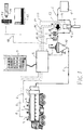
- Figure 1 shows a system for sampling milk by a method according to the invention.
- 1 indicates a farm tank
- 2 indicates a tank lorry
- 3 indicates a sample bottle
- 4 indicates a sampling valve
- 5 indicates a drain pipe, which transports the milk from the farm tank 1 to the tank lorry 2.
- the system comprises a control and data processing unit 6, which is connected with a keyboard 7.
- the unit 6 is via pipes 8 connected with sensors 9 on the tank lorry 2 in order to monitor the level in the tank.
- the unit 6 is via a pipe 10 connected with a bar code reader 11 for reading a bar code 15, which is positioned on the sample bottle 3.
- the unit 6 is also made for recording a magnetic card 12, which is individual for each and single supplier.
- the unit 6 is given information about the individual supplier just as it is ensured that the sample bottle in question belongs to the supplier in question.
- the system may via the keyboard 7 or via the magnetic card 12 be provided with information about the amount of milk to be fetched from the farm tank 1.
- the system shown is a pressure system and comprises a pump 13, which is inserted in the drain pipe 5.
- the pump 13 is via the control wires 14 connected with the unit 6.
- the drain pipe 5 is provided with sensors 16, which measure the different parametres in the milk, and transmit the signals about this to the unit 6 via wires 17.
- a well-known air trap 18 is inserted in the drain pipe 5.
- the sampling valve 4 is inserted into a branching pipe 19 parallel to the pump 13.
- the branching pipe 19 connects the pressure side of the pump and the suction side of the pump for establishing a flow through the valve 4.
- the valve 4 is via a control wire 20 connected with the unit 6.
- valve 4 shown schematically in Figure 1 may be of the type illustrated in Figure 2 or of the type illustrated in Figures 3-6.
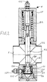
- FIG 2 illustrates a first embodiment of a valve 4.
- the valve comprises a valve casing 21, in which a cylinder piston 22 may be displaced backwards and forwards for a reciprocal movement.
- the piston 22 is provided with an annular groove 23 in the vicinity of its free end.
- the piston 22 passes through the drain pipe 5, which may be intended for a vacuum system or a pressure system as illustrated in Figure 1.
- the piston 22 has such a travel that the lowest end 24, which contains the annular groove 23, may be displaced past a lining 25, which is located between the drain pipe 5 and a discharge opening 26 for the valve 4.
- the annular groove 23 may be cut off completely by the lining 25.
- the piston may be led all the way down to a chamber 27 in connection with the discharge opening 26. Consequently, the milk may now run freely out of the discharge opening, irrespective of the drain pipe 5 being subjected to vacuum or to pressure. This is possible as the annular groove 23 is disconnected with the drain pipe 5.
- the piston 22 has, in an area 128 adjacent to the annular groove, a diameter which fits tightly in the diameter of the lining 24.
- the valve When the piston 22 has carried out a desired number of movements and has drained a desired amount of milk to a sample bottle, which is connected with the discharge opening 26 of the valve, the valve may be blown clean by means of an air supply 129, which via an annular passage 130 and radial passages 131 is in connection with the chamber 27. By inserting a sample bottle milk leftovers from a previous supplier will not exist.
- the piston 22 in the valve 4 is operated pneumatically and is activated for a downwardly directed stroke by air supply via an inlet connecting piece 132.
- the return movement of the piston is established by means of a spring 133. It is noted that alternative methods for operating the piston 22 are possible. It is solely to be ensured that the piston in its first outer position as illustrated in Figure 2, is in connection with the drain pipe 5, and that the annular groove 23 in the second outer position of the piston is in connection with the discharge opening 26.
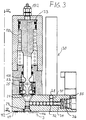
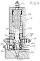
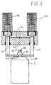
- FIGs 3-6 illustrate an alternative embodiment of a valve according to the invention. As several parts are repeated in the two embodiments, only a specific explanation will be given of the elements, which differentiate the two embodiments.
- This valve may also be used in a pressure system or a vacuum system.
- the situtation illustrated corresponds to Figure 1 as the valve is not inserted directly via a drain pipe 5 as shown in Figure 2.
- the valve 4 is connected with a branching wire 19, which because of the pump 13 fills a chamber 34 with milk.
- This chamber will be in connection with the annular groove 23 in the first outer position of the piston 22, which is shown with full-drawn lines.
- the annular groove 23 has an axial extension which also here, is less than the axial extension of the lining 25.
- the groove 23 may, at its downwardly directed stroke towards the second outer position which is shown with thin lines, pass by the lining 25, which delimits a well-defined capacity in the groove 23.
- the annular groove 23 will, as illustrated with thin lines, be in connection with the chamber 27 above the discharge opening 26. Consequently, the milk may run down into the sample bottle 3.
- Figures 3 and 4 illustrate the final stroke of the piston 22, where a ball 28 has been pressed into the neck 29 of the bottle 3.
- the ball comes from a storage 30 for balls, which is connected with the valve 4. From the bottom of the storage 30 for balls, balls are led through a vertical passage 31 to a horizontal passage 32, which is located substantially perpendicular to an axis 33, which extends through the piston 22 and the neck 29 of the bottle.
- a row of balls are placed, or merely a single ball 28, depending on the length of the passage 32.
- a piston 34 is positioned, which by activating through a compressed air pipe 35, may press a ball into the discharge opening 26 beneath the outermost end part 24 of the piston 22.
- the piston 34 is returned by means of a spring 36.
- the piston 34 is activated as a result of a signal from the unit 6.
- the balls 28 are preferably steel balls, which have an oversize in relation to the diameter of the neck 29 of the bottle, which is of plastic. After the pressing, the ball will thus deform the neck of the bottle. Because of the form of the neck of the bottle having a collar in the form of an annular shell 37 ( Figure 5), there is no risk of breaking the neck of the bottle.
- Figure 5 illustrates the two pistons 39, which support a plate 40, provided with a recess 41.
- the bottle 3 may be positioned in the recess 41, and will be aligned with the discharge opening 26 as an annular groove 42 (see Figure 4), which is formed below the collar 37, is positioned in the recess 41.
- the pistons 39 are subsequently activated by compressed air via a passage 43. Consequently, the neck 29 of the bottle is pressed up into the discharge opening 26 in a sealing engagement.
- the return movement of the pistons 39 is ensured by means of springs 44.
- the bottle 3 is provided with a membrane 45, which covers the opening of the neck of the bottle, and which will be broken by the first piston stroke as the outermost end part 24 of the piston 22 penetrates into the neck of the bottle.
- the bottle 3 will be secured during the entire filling and during the above described sealing with the ball 29. As the entire process is controlled and monitored by the unit 6, an unintended or inadmissible manipulating with the sampling will be prevented.
- the engaging mean may quite simply be constituted of the plane plate 40, in which the bottle 3 in a safe way is suspended in the recess 41.
- the collar 37 is truncated cone-shaped a large support surface 46 is obtained, which rests on the top side of the plate 40. This gives a stable support so the bottle does not turn over when it is pressed into the discharge opening 26.
- the large support surface is simultaneously advantageous for a safe securing of the bottle below the pressing of the ball 28 into the neck of the bottle. Consequently, the ball may be pressed with great force which causes a deforming of the neck of the bottle.
- the material in the neck will resiliently be restored to its original position so that the ball cannot be removed.
- the neck may quite simply be cut off together with the steel ball by cutting in the bottom of the annular groove 42.
- Figure 6 illustrates the valve seen from above.
- the placing of the storage 30 for balls and the placing of two casings 48 are seen, said casings containing the pistons 39 and the springs 44.
- a connection arrangement 49 is shown through which the valve 4 is connected with the unit 6.
Landscapes
- Life Sciences & Earth Sciences (AREA)
- Hydrology & Water Resources (AREA)
- Physics & Mathematics (AREA)
- Health & Medical Sciences (AREA)
- Chemical & Material Sciences (AREA)
- Analytical Chemistry (AREA)
- Biochemistry (AREA)
- General Health & Medical Sciences (AREA)
- General Physics & Mathematics (AREA)
- Immunology (AREA)
- Pathology (AREA)
- Sampling And Sample Adjustment (AREA)
- Dairy Products (AREA)
Applications Claiming Priority (3)
| Application Number | Priority Date | Filing Date | Title |
|---|---|---|---|
| DK062892A DK171066B1 (da) | 1992-05-13 | 1992-05-13 | Fremgangsmåde samt ventil til udtagning af mælkeprøver samt flaske til brug ved en sådan prøveudtagning |
| DK628/92 | 1992-05-13 | ||
| DK62892 | 1992-05-13 |
Publications (2)
| Publication Number | Publication Date |
|---|---|
| EP0569830A1 true EP0569830A1 (fr) | 1993-11-18 |
| EP0569830B1 EP0569830B1 (fr) | 1999-06-23 |
Family
ID=8095740
Family Applications (1)
| Application Number | Title | Priority Date | Filing Date |
|---|---|---|---|
| EP93107253A Expired - Lifetime EP0569830B1 (fr) | 1992-05-13 | 1993-05-05 | Méthode et vanne pour le prélèvement de lait et bouteille pour tel prélèvement |
Country Status (4)
| Country | Link |
|---|---|
| EP (1) | EP0569830B1 (fr) |
| AT (1) | ATE181591T1 (fr) |
| DE (1) | DE69325414T2 (fr) |
| DK (1) | DK171066B1 (fr) |
Cited By (3)
| Publication number | Priority date | Publication date | Assignee | Title |
|---|---|---|---|---|
| FR2882822A1 (fr) * | 2005-03-01 | 2006-09-08 | Magyar Sa Ets | Dispositif de prelevement d'un echantillon "global" de liquide |
| DE102009009552A1 (de) * | 2009-02-19 | 2010-09-02 | Gea Diessel Gmbh | Verfahren und Vorrichtung für eine Probennahme an Produkten |
| FR2997501A1 (fr) * | 2012-10-29 | 2014-05-02 | Jean Mainguet | Dispositif de prelevement confine de liquide, notamment de lait |
Citations (5)
| Publication number | Priority date | Publication date | Assignee | Title |
|---|---|---|---|---|
| DE1065187B (de) * | 1959-09-10 | Rendsburg Heinrich Kortum | Vorrichtung zum Abzweigen eines proportionalen Teilstromes aus einer flüssigkeitsdurchströmten Rohrleitung | |
| CH544302A (de) * | 1971-10-18 | 1973-11-15 | Ciba Geigy Ag | Vorrichtung zur Entnahme von Proben |
| DE2453473A1 (de) * | 1974-11-12 | 1976-05-13 | Schwarte Gmbh Alfons | Geraet zur entnahme von milchproben |
| DE8701550U1 (de) * | 1987-02-02 | 1987-03-19 | Röhm GmbH, 6100 Darmstadt | Probennehmer für durchströmte Rohrleitungen |
| US4744255A (en) * | 1987-03-23 | 1988-05-17 | Jaeger Ben E | Sampler and metering pump |
-
1992
- 1992-05-13 DK DK062892A patent/DK171066B1/da not_active IP Right Cessation
-
1993
- 1993-05-05 EP EP93107253A patent/EP0569830B1/fr not_active Expired - Lifetime
- 1993-05-05 DE DE69325414T patent/DE69325414T2/de not_active Expired - Fee Related
- 1993-05-05 AT AT93107253T patent/ATE181591T1/de not_active IP Right Cessation
Patent Citations (5)
| Publication number | Priority date | Publication date | Assignee | Title |
|---|---|---|---|---|
| DE1065187B (de) * | 1959-09-10 | Rendsburg Heinrich Kortum | Vorrichtung zum Abzweigen eines proportionalen Teilstromes aus einer flüssigkeitsdurchströmten Rohrleitung | |
| CH544302A (de) * | 1971-10-18 | 1973-11-15 | Ciba Geigy Ag | Vorrichtung zur Entnahme von Proben |
| DE2453473A1 (de) * | 1974-11-12 | 1976-05-13 | Schwarte Gmbh Alfons | Geraet zur entnahme von milchproben |
| DE8701550U1 (de) * | 1987-02-02 | 1987-03-19 | Röhm GmbH, 6100 Darmstadt | Probennehmer für durchströmte Rohrleitungen |
| US4744255A (en) * | 1987-03-23 | 1988-05-17 | Jaeger Ben E | Sampler and metering pump |
Cited By (4)
| Publication number | Priority date | Publication date | Assignee | Title |
|---|---|---|---|---|
| FR2882822A1 (fr) * | 2005-03-01 | 2006-09-08 | Magyar Sa Ets | Dispositif de prelevement d'un echantillon "global" de liquide |
| DE102009009552A1 (de) * | 2009-02-19 | 2010-09-02 | Gea Diessel Gmbh | Verfahren und Vorrichtung für eine Probennahme an Produkten |
| DE102009009552B4 (de) * | 2009-02-19 | 2011-06-22 | GEA Diessel GmbH, 31135 | Verfahren und Vorrichtung für eine Probennahme an Produkten |
| FR2997501A1 (fr) * | 2012-10-29 | 2014-05-02 | Jean Mainguet | Dispositif de prelevement confine de liquide, notamment de lait |
Also Published As
| Publication number | Publication date |
|---|---|
| DE69325414D1 (de) | 1999-07-29 |
| ATE181591T1 (de) | 1999-07-15 |
| DE69325414T2 (de) | 2000-01-13 |
| EP0569830B1 (fr) | 1999-06-23 |
| DK62892D0 (da) | 1992-05-13 |
| DK62892A (da) | 1993-11-14 |
| DK171066B1 (da) | 1996-05-13 |
Similar Documents
| Publication | Publication Date | Title |
|---|---|---|
| KR100568527B1 (ko) | 캡슐 포장기용 검사 및 제어 장치 | |
| AU692222B2 (en) | System to facilitate recycling goods from defective packages on a blister packaging machine | |
| US8211381B2 (en) | Device for performing analyses on biological fluids and related method | |
| US20100162548A1 (en) | Device and method for mounting a needle guard on a syringe body | |
| CN101541262B (zh) | 用精液填充人工受精吸管的机器 | |
| CN88103285A (zh) | 使混合后饮料分配器的碳酸化器之充碳酸气作用得到改进的系统 | |
| EP0569830B1 (fr) | Méthode et vanne pour le prélèvement de lait et bouteille pour tel prélèvement | |
| GB2203496B (en) | Process for filling a container, a device for this purpose and a method for its operation. | |
| CN114137242A (zh) | 一种全自动检测污水中微量毒品的装置 | |
| US20050005968A1 (en) | Automated vacuum waste handling system | |
| EP0273108B1 (fr) | Dispositif de contrôle de niveau de remplissage | |
| GB2352035A (en) | Liquid sampling | |
| US4476534A (en) | Fixed-cycle-controlled filling machine | |
| GB2385010A (en) | Device for fully automated solid phase extraction | |
| EP0157437A2 (fr) | Dispositif pour aérer ou désaérer des liquides circulant dans un conduit | |
| EP0410332A2 (fr) | Méthode et appareil pour charger un liquide | |
| CN218487686U (zh) | 一种气动电磁阀内部卡圈压装机构 | |
| DE102009009552B4 (de) | Verfahren und Vorrichtung für eine Probennahme an Produkten | |
| US5551312A (en) | Device for sampling and pumping liquids contained in a chemical reaction vessel, drum or storage tank | |
| CA1308542C (fr) | Dispositif de mise en place d'un robinet sur une boite d'aerosol | |
| EP0982265A3 (fr) | Procédé et dispositif pour le transvasement de liquide | |
| EP1929447B1 (fr) | Dispositif de stockage et de traction et procédé de manipulation correspondant | |
| EP0370369B1 (fr) | Système de transport de caillé | |
| SU1645239A1 (ru) | Разливочна машина | |
| CS222837B1 (cs) | Zařízení pro středění lahví vůči plnicímu ventilu lahvové plničky |
Legal Events
| Date | Code | Title | Description |
|---|---|---|---|
| PUAI | Public reference made under article 153(3) epc to a published international application that has entered the european phase |
Free format text: ORIGINAL CODE: 0009012 |
|
| AK | Designated contracting states |
Kind code of ref document: A1 Designated state(s): AT BE CH DE ES FR GB IT LI NL PT SE |
|
| 17P | Request for examination filed |
Effective date: 19940518 |
|
| 17Q | First examination report despatched |
Effective date: 19950425 |
|
| GRAG | Despatch of communication of intention to grant |
Free format text: ORIGINAL CODE: EPIDOS AGRA |
|
| GRAG | Despatch of communication of intention to grant |
Free format text: ORIGINAL CODE: EPIDOS AGRA |
|
| GRAH | Despatch of communication of intention to grant a patent |
Free format text: ORIGINAL CODE: EPIDOS IGRA |
|
| GRAH | Despatch of communication of intention to grant a patent |
Free format text: ORIGINAL CODE: EPIDOS IGRA |
|
| GRAA | (expected) grant |
Free format text: ORIGINAL CODE: 0009210 |
|
| AK | Designated contracting states |
Kind code of ref document: B1 Designated state(s): AT BE CH DE ES FR GB IT LI NL PT SE |
|
| PG25 | Lapsed in a contracting state [announced via postgrant information from national office to epo] |
Ref country code: SE Free format text: THE PATENT HAS BEEN ANNULLED BY A DECISION OF A NATIONAL AUTHORITY Effective date: 19990623 Ref country code: NL Free format text: LAPSE BECAUSE OF FAILURE TO SUBMIT A TRANSLATION OF THE DESCRIPTION OR TO PAY THE FEE WITHIN THE PRESCRIBED TIME-LIMIT Effective date: 19990623 Ref country code: LI Free format text: LAPSE BECAUSE OF FAILURE TO SUBMIT A TRANSLATION OF THE DESCRIPTION OR TO PAY THE FEE WITHIN THE PRESCRIBED TIME-LIMIT Effective date: 19990623 Ref country code: IT Free format text: LAPSE BECAUSE OF FAILURE TO SUBMIT A TRANSLATION OF THE DESCRIPTION OR TO PAY THE FEE WITHIN THE PRE;WARNING: LAPSES OF ITALIAN PATENTS WITH EFFECTIVE DATE BEFORE 2007 MAY HAVE OCCURRED AT ANY TIME BEFORE 2007. THE CORRECT EFFECTIVE DATE MAY BE DIFFERENT FROM THE ONE RECORDED.SCRIBED TIME-LIMIT Effective date: 19990623 Ref country code: FR Free format text: LAPSE BECAUSE OF FAILURE TO SUBMIT A TRANSLATION OF THE DESCRIPTION OR TO PAY THE FEE WITHIN THE PRESCRIBED TIME-LIMIT Effective date: 19990623 Ref country code: ES Free format text: THE PATENT HAS BEEN ANNULLED BY A DECISION OF A NATIONAL AUTHORITY Effective date: 19990623 Ref country code: CH Free format text: LAPSE BECAUSE OF FAILURE TO SUBMIT A TRANSLATION OF THE DESCRIPTION OR TO PAY THE FEE WITHIN THE PRESCRIBED TIME-LIMIT Effective date: 19990623 Ref country code: BE Free format text: LAPSE BECAUSE OF FAILURE TO SUBMIT A TRANSLATION OF THE DESCRIPTION OR TO PAY THE FEE WITHIN THE PRESCRIBED TIME-LIMIT Effective date: 19990623 Ref country code: AT Free format text: LAPSE BECAUSE OF FAILURE TO SUBMIT A TRANSLATION OF THE DESCRIPTION OR TO PAY THE FEE WITHIN THE PRESCRIBED TIME-LIMIT Effective date: 19990623 |
|
| REF | Corresponds to: |
Ref document number: 181591 Country of ref document: AT Date of ref document: 19990715 Kind code of ref document: T |
|
| REG | Reference to a national code |
Ref country code: CH Ref legal event code: EP |
|
| REF | Corresponds to: |
Ref document number: 69325414 Country of ref document: DE Date of ref document: 19990729 |
|
| PG25 | Lapsed in a contracting state [announced via postgrant information from national office to epo] |
Ref country code: PT Free format text: LAPSE BECAUSE OF FAILURE TO SUBMIT A TRANSLATION OF THE DESCRIPTION OR TO PAY THE FEE WITHIN THE PRESCRIBED TIME-LIMIT Effective date: 19990923 |
|
| EN | Fr: translation not filed | ||
| NLV1 | Nl: lapsed or annulled due to failure to fulfill the requirements of art. 29p and 29m of the patents act | ||
| REG | Reference to a national code |
Ref country code: CH Ref legal event code: PL |
|
| PLBE | No opposition filed within time limit |
Free format text: ORIGINAL CODE: 0009261 |
|
| PG25 | Lapsed in a contracting state [announced via postgrant information from national office to epo] |
Ref country code: GB Free format text: LAPSE BECAUSE OF NON-PAYMENT OF DUE FEES Effective date: 20000505 |
|
| 26N | No opposition filed | ||
| GBPC | Gb: european patent ceased through non-payment of renewal fee |
Effective date: 20000505 |
|
| PGFP | Annual fee paid to national office [announced via postgrant information from national office to epo] |
Ref country code: DE Payment date: 20010731 Year of fee payment: 9 |
|
| PG25 | Lapsed in a contracting state [announced via postgrant information from national office to epo] |
Ref country code: DE Free format text: LAPSE BECAUSE OF NON-PAYMENT OF DUE FEES Effective date: 20021203 |