EP0569836A1 - Dispositif tracteur équipé d'au moins un outil monté pivotant - Google Patents
Dispositif tracteur équipé d'au moins un outil monté pivotant Download PDFInfo
- Publication number
- EP0569836A1 EP0569836A1 EP93107268A EP93107268A EP0569836A1 EP 0569836 A1 EP0569836 A1 EP 0569836A1 EP 93107268 A EP93107268 A EP 93107268A EP 93107268 A EP93107268 A EP 93107268A EP 0569836 A1 EP0569836 A1 EP 0569836A1
- Authority
- EP
- European Patent Office
- Prior art keywords
- cylinder
- vehicle
- working position
- working
- vehicle according
- Prior art date
- Legal status (The legal status is an assumption and is not a legal conclusion. Google has not performed a legal analysis and makes no representation as to the accuracy of the status listed.)
- Granted
Links
Images


Classifications
-
- A—HUMAN NECESSITIES
- A01—AGRICULTURE; FORESTRY; ANIMAL HUSBANDRY; HUNTING; TRAPPING; FISHING
- A01D—HARVESTING; MOWING
- A01D34/00—Mowers; Mowing apparatus of harvesters
- A01D34/01—Mowers; Mowing apparatus of harvesters characterised by features relating to the type of cutting apparatus
- A01D34/412—Mowers; Mowing apparatus of harvesters characterised by features relating to the type of cutting apparatus having rotating cutters
- A01D34/42—Mowers; Mowing apparatus of harvesters characterised by features relating to the type of cutting apparatus having rotating cutters having cutters rotating about a horizontal axis, e.g. cutting-cylinders
- A01D34/43—Mowers; Mowing apparatus of harvesters characterised by features relating to the type of cutting apparatus having rotating cutters having cutters rotating about a horizontal axis, e.g. cutting-cylinders mounted on a vehicle, e.g. a tractor, or drawn by an animal or a vehicle
- A01D34/44—Mowers; Mowing apparatus of harvesters characterised by features relating to the type of cutting apparatus having rotating cutters having cutters rotating about a horizontal axis, e.g. cutting-cylinders mounted on a vehicle, e.g. a tractor, or drawn by an animal or a vehicle with two or more cutters
-
- A—HUMAN NECESSITIES
- A01—AGRICULTURE; FORESTRY; ANIMAL HUSBANDRY; HUNTING; TRAPPING; FISHING
- A01D—HARVESTING; MOWING
- A01D67/00—Undercarriages or frames specially adapted for harvesters or mowers; Mechanisms for adjusting the frame; Platforms
-
- A—HUMAN NECESSITIES
- A01—AGRICULTURE; FORESTRY; ANIMAL HUSBANDRY; HUNTING; TRAPPING; FISHING
- A01D—HARVESTING; MOWING
- A01D34/00—Mowers; Mowing apparatus of harvesters
- A01D34/01—Mowers; Mowing apparatus of harvesters characterised by features relating to the type of cutting apparatus
- A01D34/412—Mowers; Mowing apparatus of harvesters characterised by features relating to the type of cutting apparatus having rotating cutters
- A01D34/42—Mowers; Mowing apparatus of harvesters characterised by features relating to the type of cutting apparatus having rotating cutters having cutters rotating about a horizontal axis, e.g. cutting-cylinders
- A01D34/62—Other details
-
- A—HUMAN NECESSITIES
- A01—AGRICULTURE; FORESTRY; ANIMAL HUSBANDRY; HUNTING; TRAPPING; FISHING
- A01D—HARVESTING; MOWING
- A01D75/00—Accessories for harvesters or mowers
- A01D75/30—Arrangements for trailing two or more mowers
-
- A—HUMAN NECESSITIES
- A01—AGRICULTURE; FORESTRY; ANIMAL HUSBANDRY; HUNTING; TRAPPING; FISHING
- A01D—HARVESTING; MOWING
- A01D75/00—Accessories for harvesters or mowers
- A01D75/30—Arrangements for trailing two or more mowers
- A01D75/306—Arrangements for trailing two or more mowers for lawn mowers positioned one behind the other or side by side
-
- Y—GENERAL TAGGING OF NEW TECHNOLOGICAL DEVELOPMENTS; GENERAL TAGGING OF CROSS-SECTIONAL TECHNOLOGIES SPANNING OVER SEVERAL SECTIONS OF THE IPC; TECHNICAL SUBJECTS COVERED BY FORMER USPC CROSS-REFERENCE ART COLLECTIONS [XRACs] AND DIGESTS
- Y10—TECHNICAL SUBJECTS COVERED BY FORMER USPC
- Y10S—TECHNICAL SUBJECTS COVERED BY FORMER USPC CROSS-REFERENCE ART COLLECTIONS [XRACs] AND DIGESTS
- Y10S56/00—Harvesters
- Y10S56/22—Underslung yieldable rotary mower
Definitions
- the invention relates to a vehicle with at least one work tool pivotally connected to the vehicle via a support arm, which is guided in a working position on the floor surface, can perform vertical relative movements in relation to the vehicle in the working position and has a hydraulically actuatable cylinder. or is directly connected, which can be pressurized in a first direction such that the working tool can be lifted out of its working position into a transport position.
- Such a vehicle (US-A-5 042 236) is equipped with two front optionally drivable wheels, in front of which three spindle mowing units are arranged vertically pivotably in a row via the support arms.
- Each spindle mower unit is assigned a hydraulically actuated cylinder, all three of which are articulated to a frame of the vehicle and connected to the support arms via an elongated hole connection.
- the spindle mowing units can be adjusted from a working position in which they can perform vertical relative movements as a result of the elongated hole connection when they hit uneven ground, into a transport position.
- Such lawnmowers are preferably used on golf courses where a precise lawn cut is important.
- the object to be achieved with the invention is seen in making the connection device for the one or more height-adjustable work tools connected to the vehicle and guided on the ground in use.
- This object is achieved in that, in the working position of the working tool, the cylinder can be pressurized in a second direction opposite to the first direction and is arranged such that this pressure can be transmitted to the working tool. In this way, the ground pressure is created by the cylinder.
- the springs can thus be completely dispensed with, and the cylinder or cylinders which are present anyway can, in addition to their lifting function, also take on the task of pressing the working tool or tools onto the ground surface.
- the cylinder is designed such that it can be pressurized in the second direction even when the working tool is moved from its transport position into its working position.
- the lowering process can thus be controlled from the transport position and is not solely dependent on the weight of the work tool.
- the piston of the hydraulically actuatable cylinder is moved into the cylinder when it is acted upon in the first direction, it can be provided according to the invention that the piston-side end of the cylinder can be additionally pressurized in the working position of the working tool.
- the invention further provides that the pressure acting on the piston in the second direction when pressure is applied is adjustable. This can be done easily by hand.
- Such vehicles are equipped with at least one pump and a collecting container, which is why it can be proposed according to the invention that for the pressure in the second direction one end of the cylinder is connected to the pump via a line, from which a branch line connected to the collecting container branches, in which an adjustable relief valve is provided in front of the collecting container.
- the pump can be identical to the pump that causes the work tool to be lifted.
- the limiting valve is then advantageously infinitely adjustable.
- the invention further provides that the piston-side ends of the cylinders are connected to a pump supplying a consumer with pressure medium and the piston rod-side ends of the cylinders are connected to a further pump.
- One or more or all drive motors of the preferably hydraulically driven spindle mowing units can serve as consumers.
- a vehicle 10 in the form of a cylinder mower for lawn care is shown schematically, which has two drivable front wheels 12 and two rear steerable wheels 14.
- a rigid support structure or a single, preferably T-shaped frame 16 extends laterally between the two front wheels 12 and rearward in the longitudinal direction of the vehicle between the front and rear wheels 12 and 14.
- a plurality of arms 18 extending horizontally in the working position , 20, 22, 24 and 26 has a Z-shape in the exemplary embodiment and is equipped with inner and outer sections 28 and 30.
- the inner portions 28 are pivotally connected to the frame 16, for which purpose they are rotatably received in sleeves or bushings 32 are, which are firmly connected to the frame 16 via U-bracket 34.
- the outer sections 30 are connected to spindle mowing units 36 which, in their working position shown in FIG. 1, are guided on the floor surface via rollers or rollers, not shown, and which can be pivoted hydraulically from their position in FIG. 1 by approximately 90 ° into a raised transport position .
- spindle mowing units 36 which, in their working position shown in FIG. 1, are guided on the floor surface via rollers or rollers, not shown, and which can be pivoted hydraulically from their position in FIG. 1 by approximately 90 ° into a raised transport position .
- Fig. 1 three front and in front of the front wheels 12 and two rear and arranged between the axes spindle mowing units 36 can be seen.
- lever parts 38 in the form of vertically directed tabs, to which hydraulically actuated cylinders are connected for vertical pivoting.
- three cylinders 40, 42 and 44 are provided, the first cylinder 40 being connected to the lever parts 38 of the front arms 18 and 22 located on the outside on the right and on the left outside.
- its piston rod is provided with a corresponding extension in order to be able to bridge the distance between the two lever parts 38.
- the left and upward lever part 38 is articulated to the extension, while the right upward lever part is also articulated to the housing of the cylinder.
- the second cylinder 42 is articulated with its cylinder housing to the frame 16 and, with its piston rod, articulates against the downwardly directed lever part 38 of the central front arm 20.
- the third cylinder 44 is connected to the two rear arms 24, 26 or their lever parts 38, as will be explained in more detail below. If the piston rods of the cylinders 40 to 44 are retracted, the arms 18 to 26 and the spindle mowing units 36 connected to them are rotated upwards into their transport position. When the piston rods are extended, the spindle mowing units 36 return to their working position. In the working position, the individual spindle mowing units 36 are pressed against the ground surface by means of hydraulic pressure, as will also be explained below. At work on uneven ground, the individual spindle mower units always remain in contact with the ground surface, even when working at higher working speeds.
- FIG. 1 also shows how the third cylinder 44 is connected to the rear arms 24 and 26 or to the associated lever parts 38.
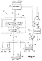
- 4 shows a hydraulic circuit 46 for actuating the individual cylinders 40 to 44, each having a piston rod-side and a piston-side end 54, 56, a first consumer, such as a steering cylinder, which can be actuated via a steering valve 48 (not shown in detail) and a second Consumers 50, such as one or more of the hydraulic drive motors of the spindle mowing units 36, a control valve 52 and a limit valve 58, which will be discussed in more detail later.
- a pair of rail parts is first pivotally connected on both sides of the rear cylinder 44 to the upward-pointing lever part 38 of the rear right arm 24.
- a pin 64 is received, which is provided on the end of the cylinder 44 remote from the piston rod.
- a further pair of rails 66 which are also provided with elongated holes, are connected to the lever part 38 of the left rear arm 26.
- a pin 70 is received therein and is attached to the end of the piston rod of the rear cylinder 44. From the drawing it can also be seen that the rail parts 60 are also provided with two further elongated holes. Now, when the third cylinder 44 is extended in the extending sense, the pins 64 and 70 move away from each other, and the rail parts 60 and the rails 66 cause, if the spindle mower units are in their working position, they are pressed onto the floor surface. On the other hand, if the third cylinder 44 is retracted, the pins 64, 70 move towards one another, and the rail parts 60 and rails 66 pivot the lever parts 38 against one another, the rear arms 24 and 26 with the spindle units 36 engaging them in their raised transport position be pivoted.
- the third cylinder is connected via a lost motion connection, and the movement of the retracting or extending piston rod is transmitted to the rail parts and rails with a time delay, so that the rear spindle mower units 36 are somewhat later than the front spindle mower units dig out.
- the control valve 52 When the operator operates the control valve 52 to raise the spindle mowers, the front mowers are raised immediately and the rear mowers only when the pins 64 and 70 have moved against the ends of their elongated holes.
- the operator switches the control valve 52 to lift, the front spindle mower units immediately starting the lifting process and the rear spindle mower units still in their working position when the vehicle 10 continues to travel can continue to mow.
- This meadow leaves no or only a small amount of uncut grass in the cutting path.
- the elongated holes provided in the rail parts 60 and rails 66 also help to keep the rear cylinder in a horizontal position during its actuation.
- the cylinders 40 to 44 are in their retracted position, in which the spindle mowing units 36 are fixed in their folded-up transport positions.
- the control valve 52 is shifted from its position shown in FIG. 4 to the left, so that hydraulic fluid delivered by a pump 76 via a pressure line 78 into one provided in the control valve Channel 80 and thus to the right side of a valve spool 82, which has a check valve 84 and another free passage 86, can reach.
- the valve spool 82 is thereby moved into its position for free flow, so that a feed line 88 leading to the ends 54 of the cylinders 40 to 46 and having a throttle is connected to a collecting container 90 via a return line 92. Liquid in the ends 54 of the cylinders 40 to 44 on the side of the piston rod can thus flow into the collecting container 90 by extending the piston rods.
- the extension takes place under the weight of the spindle mowing units 36 and can be supported by a pressure building up on the piston-side end 56 of the cylinders 40 to 44 if the motors of the spindle mowing units belonging to the second consumer 50 are driven at this time.
- the piston-side ends 56 of the cylinders 40 to 44 are connected to the outlet of the second consumer 50 via a line 94, in which there is a throttle 96 and a check valve 98.
- the line 94 is still connected via a branch line, in which the limiting valve 58 is located, to the collecting tank 90 or to the return line 92.
- the through opening in the limiting valve 58 which is pilot-controlled against the action of a spring, can be adjusted manually, as a result of which the pressure acting on the pistons of the cylinders 40 to 44 at the piston end can be changed.
- the control valve 52 For the working position, the control valve 52 remains in its position described above, in which the control valve 52 has therefore been shifted to the left from its position shown in FIG. 4.
- the ends 54 of the cylinders 40 to 44 on the piston rod side are thus connected to the collecting container 90, and the bottom pressure of the spindle mowing units 36 is determined by the pressure on the end 56 of the cylinders on the piston side.
- the motors of the spindle mowing units 36 are also driven, and liquid flowing out of the second consumer reaches the ends 56 on the piston side, depending on how the limiting valve is 58 is set, a more or less large force builds up, which determines the ground pressure of all spindle mowing units.
- Excess liquid can flow out into the collection container 90 through the limit valve 58. If one or more or all of the spindle mower units hit uneven ground, the set ground pressure is not reduced either. For example, when hitting a floor recess, the corresponding piston rod is extended, since the corresponding spindle mowing unit lowers and liquid located at the end 54 on the piston rod side can flow out into the collecting container 90. At the same time, the pressure set by the limiting valve 58 continues to act on the piston-side end 56. When it encounters ground elevations, the piston rod of the corresponding cylinder or cylinders is retracted.
- the control valve 52 is shifted from the position shown in FIG. 4 to the right, as a result of which the valve slide is returned to its position according to FIG. 4 and the pressure line 78 is connected to the feed line 88, so that the piston rod ends 54 of the cylinders 40 to 44 are pressurized and the associated piston rods are retracted. Liquid still located in the piston-side ends 56 is pressed into the collection container 90 by the limiting valve 58. Since the motors of the spindle mowing units are no longer driven during this process, the liquid at the ends 56 is also no longer under a corresponding pressure.
- the inlet of the second consumer 50 is still connected to a second pump 104 which, like the pump 76, always delivers pressure fluid as long as an internal combustion engine of the vehicle is running.
- the second consumer 50 can be switched off, so that the pressure medium delivered by the pump 104 then reaches the line 94. In such a case, pressure always builds up in the piston-side ends 56 of the cylinders 40 to 44. When the spindle mowing units are raised, the pressure in the piston-side end 56 is then overcome.
- the hydraulic drives for the spindle mowing units 36 can also be controlled by the control valve in such a way that they are automatically switched off when the spindle mower units are lifted out and in their transport position and when the Spindle mower units in the working position and in the working position are automatically switched on.
- the pressures can be adjusted continuously.
- the operator can set the ground pressure required for the individual application very precisely. Even when driving over uneven ground, the set ground pressure remains more or less constant.
- the individual cylinders are connected to one another or connected in parallel in the present exemplary embodiment in such a way that a single limit valve 58 can be used. Regardless of whether the hydraulic system works with one pump or with two pumps, the limit valve 58 should always be arranged as the last unit before the collection container 90.
- the cylinders also act transversely or at an angle of 90 ° on the associated arms, which is why the forces for swinging up the arms or for generating the desired ground pressure can be kept relatively small.
- the corresponding lever parts 38 on the arms 18 to 26 are also not adjusted significantly.
- the lever arms remain cheap and relatively small cylinders with short travel can be used, which of course makes the entire system cheaper. This also contributes to the fact that the five spindle units 36 can be actuated via only three cylinders. Instead of the three cylinders, four or five cylinders can be provided.
- Every spindle mower unit is one Assigned its own cylinder, then one end of the cylinder is pivotally connected to the frame 16 of the vehicle, as is done, for example, for the cylinder 42. Likewise, it is not excluded that the soil pressures can be individually adjusted. In such a case, a limit valve would then have to be assigned to each cylinder.
- the cylinders 40 to 44 are associated with spindle mowing units 36 for mowing large lawn areas. Instead of the spindle mowing units, other ground devices can also be used if it is important to change the ground pressure with simple means.
Landscapes
- Life Sciences & Earth Sciences (AREA)
- Environmental Sciences (AREA)
- Harvester Elements (AREA)
- Lifting Devices For Agricultural Implements (AREA)
Applications Claiming Priority (2)
| Application Number | Priority Date | Filing Date | Title |
|---|---|---|---|
| US882340 | 1992-05-13 | ||
| US07/882,340 US5297378A (en) | 1992-05-13 | 1992-05-13 | Suspension mechanism for reel mowers |
Publications (2)
| Publication Number | Publication Date |
|---|---|
| EP0569836A1 true EP0569836A1 (fr) | 1993-11-18 |
| EP0569836B1 EP0569836B1 (fr) | 1998-08-26 |
Family
ID=25380384
Family Applications (1)
| Application Number | Title | Priority Date | Filing Date |
|---|---|---|---|
| EP93107268A Expired - Lifetime EP0569836B1 (fr) | 1992-05-13 | 1993-05-05 | Dispositif tracteur équipé d'au moins un outil monté pivotant |
Country Status (5)
| Country | Link |
|---|---|
| US (1) | US5297378A (fr) |
| EP (1) | EP0569836B1 (fr) |
| JP (1) | JPH0622621A (fr) |
| CA (1) | CA2094744C (fr) |
| DE (1) | DE59308910D1 (fr) |
Cited By (1)
| Publication number | Priority date | Publication date | Assignee | Title |
|---|---|---|---|---|
| EP0856247A1 (fr) * | 1997-02-03 | 1998-08-05 | Ransomes America Corporation | Tondeuse rotative à dispositifs faucheurs disposés par groupe |
Families Citing this family (34)
| Publication number | Priority date | Publication date | Assignee | Title |
|---|---|---|---|---|
| US5628169A (en) * | 1995-01-20 | 1997-05-13 | Stiller; Daniel G. | Method and apparatus for supporting a turf mower cutting unit |
| US6052973A (en) * | 1997-01-21 | 2000-04-25 | Kubota Corporation | Lift mechanism for reel-type cutting units |
| US6336312B1 (en) | 1997-02-03 | 2002-01-08 | Textron Inc. | Gang-Type rotary lawn mower with multiple rear rollers |
| US5865016A (en) * | 1997-02-07 | 1999-02-02 | Ransomes America Corporation | Release mechanism for cutting head of a gang mower |
| US5970690A (en) * | 1997-10-24 | 1999-10-26 | Ransomes America Corporation | Leveling apparatus for a cutting head of a mower |
| US6044631A (en) * | 1998-01-30 | 2000-04-04 | Deere & Company | Cutting unit stabilizing mechanism |
| JP3474103B2 (ja) * | 1998-05-26 | 2003-12-08 | 株式会社クボタ | 芝刈機のモーア吊設装置 |
| GB2366356B (en) * | 2000-09-01 | 2004-12-01 | Ransomes Jacobsen Ltd | A turf-care apparatus |
| DE10121014A1 (de) | 2001-04-28 | 2002-11-21 | Deere & Co | Mähvorrichtung |
| CA2352993A1 (fr) * | 2001-07-13 | 2003-01-13 | Solarbear Corporation | Vehicule electrique et train de faucheuse a rouleaux |
| FR2837347B1 (fr) * | 2002-03-21 | 2004-07-30 | Kuhn Sa | Faucheuse agricole comportant un vehicule porteur et plusieurs unites de travail |
| US20050034438A1 (en) * | 2003-02-12 | 2005-02-17 | Burke Steven A. | Towable rotary mowing apparatus |
| US7287363B2 (en) * | 2004-04-20 | 2007-10-30 | Deere & Company | Riding mower having multiple cutting units |
| US20060070365A1 (en) * | 2004-09-30 | 2006-04-06 | Jeff Laskowski | Articulating deck mower with inverted "V" cutter deck arrangement |
| US7089722B2 (en) * | 2004-09-30 | 2006-08-15 | Wood-Mizer Products, Inc. | Articulating deck mower with deck height adjuster |
| US7331166B2 (en) | 2005-01-28 | 2008-02-19 | Deere & Company | Coupling mechanism for mower cutting units |
| USD536709S1 (en) * | 2005-11-22 | 2007-02-13 | Paul A. Kullhem | Gang type rotary lawnmower |
| US7631478B2 (en) | 2006-05-05 | 2009-12-15 | Deere & Company | Electric implement lift system for mower cutting units |
| US7654065B2 (en) | 2006-09-12 | 2010-02-02 | Deere & Company | Offsetting cutting units for a grass mowing machine |
| US7971417B2 (en) | 2006-12-05 | 2011-07-05 | Deere & Company | Elective down pressure system for cutting units of grass mowing machine |
| US7971415B2 (en) * | 2008-05-28 | 2011-07-05 | Deere & Company | Grass mowing machine having adjustable width toolbar for mounting cutting units |
| US8109069B2 (en) * | 2009-04-30 | 2012-02-07 | The Toro Company | Proportional counterbalance system for mower cutting units |
| US8136334B2 (en) | 2010-02-17 | 2012-03-20 | Deere & Company | Reel mower cutting unit with gauge wheels |
| US8769916B2 (en) * | 2011-05-09 | 2014-07-08 | Marloo Equipment, Llc | Farm implement for harvesting and mowing that is relesably couplable to and powered by a tractor |
| US8745838B2 (en) | 2011-06-23 | 2014-06-10 | Deere & Company | Ball joint assembly for attaching cutting unit to yoke |
| US8777508B2 (en) | 2011-06-23 | 2014-07-15 | Deere & Company | Cutting unit mounting device |
| DE102011051981A1 (de) * | 2011-07-20 | 2013-01-24 | Cnh Belgium Nv | Modulares landwirtschaftliches Schneidwerk für eine Arbeitsmaschine |
| JP5968772B2 (ja) * | 2012-12-12 | 2016-08-10 | 株式会社共栄社 | 多連モアのモアユニット昇降油圧回路 |
| US20140223878A1 (en) * | 2013-02-08 | 2014-08-14 | Robert Sassone | Lawn Mower Assemblies |
| JP5940623B2 (ja) * | 2014-10-21 | 2016-06-29 | 株式会社Ihiシバウラ | 芝刈り車両 |
| JP6786097B2 (ja) * | 2015-07-31 | 2020-11-18 | 伊東電機株式会社 | 草刈り機 |
| US10136579B2 (en) * | 2017-01-20 | 2018-11-27 | David D. Button | Mower for attachment to an agricultural vehicle |
| US10390488B2 (en) | 2017-08-08 | 2019-08-27 | Deere & Company | Triplex greensmower lift system |
| US12616094B2 (en) | 2020-06-30 | 2026-05-05 | Cnh Industrial America Llc | Gauge wheel control system for an agricultural system |
Citations (6)
| Publication number | Priority date | Publication date | Assignee | Title |
|---|---|---|---|---|
| GB1601738A (en) * | 1978-05-31 | 1981-11-04 | Ahi Whimpway Ltd | Implement trailer |
| US4370846A (en) * | 1980-10-17 | 1983-02-01 | Brouwer Turf Equipment Limited | Gang mower with single cylinder lifting mechanism |
| GB2151446A (en) * | 1983-12-20 | 1985-07-24 | Kidd Farm Machinery | Mower |
| US4864805A (en) * | 1987-09-04 | 1989-09-12 | The Toro Company | System for supporting a working unit |
| US5042236A (en) * | 1990-02-08 | 1991-08-27 | The Toro Company | Cutting reel suspension with adjustable spring downloading |
| US5146733A (en) * | 1991-03-05 | 1992-09-15 | Klaeger Joseph H | Wide swath mower and method of mowing |
Family Cites Families (5)
| Publication number | Priority date | Publication date | Assignee | Title |
|---|---|---|---|---|
| US1900726A (en) * | 1930-12-20 | 1933-03-07 | Toro Mfg Company | Lawn mower |
| NL159259B (nl) * | 1950-02-14 | Ransomes Sims & Jefferies Ltd | Maaimachine. | |
| US3824772A (en) * | 1972-01-25 | 1974-07-23 | Hahn Inc | Turf maintenance machine |
| US4178741A (en) * | 1978-08-17 | 1979-12-18 | The Toro Company | Safety system for riding mower |
| US4769976A (en) * | 1987-02-11 | 1988-09-13 | The Toro Company | Method and apparatus for supporting a reel unit |
-
1992
- 1992-05-13 US US07/882,340 patent/US5297378A/en not_active Expired - Lifetime
-
1993
- 1993-04-23 CA CA002094744A patent/CA2094744C/fr not_active Expired - Fee Related
- 1993-05-05 DE DE59308910T patent/DE59308910D1/de not_active Expired - Fee Related
- 1993-05-05 EP EP93107268A patent/EP0569836B1/fr not_active Expired - Lifetime
- 1993-05-10 JP JP5108356A patent/JPH0622621A/ja active Pending
Patent Citations (6)
| Publication number | Priority date | Publication date | Assignee | Title |
|---|---|---|---|---|
| GB1601738A (en) * | 1978-05-31 | 1981-11-04 | Ahi Whimpway Ltd | Implement trailer |
| US4370846A (en) * | 1980-10-17 | 1983-02-01 | Brouwer Turf Equipment Limited | Gang mower with single cylinder lifting mechanism |
| GB2151446A (en) * | 1983-12-20 | 1985-07-24 | Kidd Farm Machinery | Mower |
| US4864805A (en) * | 1987-09-04 | 1989-09-12 | The Toro Company | System for supporting a working unit |
| US5042236A (en) * | 1990-02-08 | 1991-08-27 | The Toro Company | Cutting reel suspension with adjustable spring downloading |
| US5146733A (en) * | 1991-03-05 | 1992-09-15 | Klaeger Joseph H | Wide swath mower and method of mowing |
Cited By (1)
| Publication number | Priority date | Publication date | Assignee | Title |
|---|---|---|---|---|
| EP0856247A1 (fr) * | 1997-02-03 | 1998-08-05 | Ransomes America Corporation | Tondeuse rotative à dispositifs faucheurs disposés par groupe |
Also Published As
| Publication number | Publication date |
|---|---|
| JPH0622621A (ja) | 1994-02-01 |
| EP0569836B1 (fr) | 1998-08-26 |
| CA2094744C (fr) | 1995-07-25 |
| US5297378A (en) | 1994-03-29 |
| DE59308910D1 (de) | 1998-10-01 |
Similar Documents
| Publication | Publication Date | Title |
|---|---|---|
| EP0569836B1 (fr) | Dispositif tracteur équipé d'au moins un outil monté pivotant | |
| EP0168665B1 (fr) | Dispositif à andains montée à l'arrière d'une moissonneuse | |
| DE2922355C3 (de) | Aus Ackerschlepper mit Dreipunktanhängung und Kraftheber sowie einem Anbaugerät bestehende Geräteeinheit | |
| EP0234585A2 (fr) | Moissonneuse-batteuse | |
| DE102005046552A1 (de) | Landwirtschaftliche Kolbenpresse | |
| DE10026500A1 (de) | Erntegerät | |
| EP1179293B1 (fr) | Dispositif de commande pour un timon d'attelage | |
| EP1142467B1 (fr) | Dispositif de cueillette de céréales | |
| EP1051895A2 (fr) | Contrôle pour machine de travail agricole | |
| EP0388801A2 (fr) | Dispositif de levage hydraulique | |
| EP1169907A1 (fr) | Dispositif inverseur pour machine agricole de récolte | |
| DE9112331U1 (de) | Mähmaschine | |
| DE2262922A1 (de) | Traktor | |
| DE2632002C2 (de) | Mähmaschine | |
| DE10206507A1 (de) | Einrichtung zum Bewegen einer Arbeitseinheit | |
| DE69205209T2 (de) | Mähmaschine. | |
| CH719870A2 (de) | Mähvorrichtung für ein Trägerfahrzeug. | |
| WO2016110290A1 (fr) | Engin agricole à châssis de roulement supplémentaire | |
| EP1378157B1 (fr) | Dispositif pour faucher et/ou couper | |
| DE102011111251B4 (de) | Landmaschine | |
| DE3116984C2 (fr) | ||
| AT501973B1 (de) | Landmaschine | |
| DE60007685T2 (de) | Böschungsmäher | |
| EP4252503B1 (fr) | Faucheuse agricole pouvant fonctionner en poussée | |
| EP3598882A1 (fr) | Accessoire agricole |
Legal Events
| Date | Code | Title | Description |
|---|---|---|---|
| PUAI | Public reference made under article 153(3) epc to a published international application that has entered the european phase |
Free format text: ORIGINAL CODE: 0009012 |
|
| AK | Designated contracting states |
Kind code of ref document: A1 Designated state(s): DE FR GB IT SE |
|
| 17P | Request for examination filed |
Effective date: 19930930 |
|
| 17Q | First examination report despatched |
Effective date: 19951023 |
|
| GRAG | Despatch of communication of intention to grant |
Free format text: ORIGINAL CODE: EPIDOS AGRA |
|
| GRAG | Despatch of communication of intention to grant |
Free format text: ORIGINAL CODE: EPIDOS AGRA |
|
| GRAH | Despatch of communication of intention to grant a patent |
Free format text: ORIGINAL CODE: EPIDOS IGRA |
|
| GRAH | Despatch of communication of intention to grant a patent |
Free format text: ORIGINAL CODE: EPIDOS IGRA |
|
| GRAA | (expected) grant |
Free format text: ORIGINAL CODE: 0009210 |
|
| AK | Designated contracting states |
Kind code of ref document: B1 Designated state(s): DE FR GB IT SE |
|
| REF | Corresponds to: |
Ref document number: 59308910 Country of ref document: DE Date of ref document: 19981001 |
|
| ET | Fr: translation filed | ||
| GBT | Gb: translation of ep patent filed (gb section 77(6)(a)/1977) |
Effective date: 19981026 |
|
| PLBE | No opposition filed within time limit |
Free format text: ORIGINAL CODE: 0009261 |
|
| 26N | No opposition filed | ||
| REG | Reference to a national code |
Ref country code: GB Ref legal event code: IF02 |
|
| PGFP | Annual fee paid to national office [announced via postgrant information from national office to epo] |
Ref country code: DE Payment date: 20080421 Year of fee payment: 16 |
|
| PGFP | Annual fee paid to national office [announced via postgrant information from national office to epo] |
Ref country code: IT Payment date: 20080529 Year of fee payment: 16 |
|
| PGFP | Annual fee paid to national office [announced via postgrant information from national office to epo] |
Ref country code: SE Payment date: 20080529 Year of fee payment: 16 |
|
| REG | Reference to a national code |
Ref country code: FR Ref legal event code: ST Effective date: 20100129 |
|
| PG25 | Lapsed in a contracting state [announced via postgrant information from national office to epo] |
Ref country code: FR Free format text: LAPSE BECAUSE OF NON-PAYMENT OF DUE FEES Effective date: 20090602 |
|
| PGFP | Annual fee paid to national office [announced via postgrant information from national office to epo] |
Ref country code: FR Payment date: 20080519 Year of fee payment: 16 |
|
| PG25 | Lapsed in a contracting state [announced via postgrant information from national office to epo] |
Ref country code: DE Free format text: LAPSE BECAUSE OF NON-PAYMENT OF DUE FEES Effective date: 20091201 |
|
| PG25 | Lapsed in a contracting state [announced via postgrant information from national office to epo] |
Ref country code: IT Free format text: LAPSE BECAUSE OF NON-PAYMENT OF DUE FEES Effective date: 20090505 |
|
| PG25 | Lapsed in a contracting state [announced via postgrant information from national office to epo] |
Ref country code: SE Free format text: LAPSE BECAUSE OF NON-PAYMENT OF DUE FEES Effective date: 20090506 |
|
| PGFP | Annual fee paid to national office [announced via postgrant information from national office to epo] |
Ref country code: GB Payment date: 20120525 Year of fee payment: 20 |
|
| REG | Reference to a national code |
Ref country code: GB Ref legal event code: PE20 Expiry date: 20130504 |
|
| PG25 | Lapsed in a contracting state [announced via postgrant information from national office to epo] |
Ref country code: GB Free format text: LAPSE BECAUSE OF EXPIRATION OF PROTECTION Effective date: 20130504 |