EP0569855A1 - Installation et procédé pour le coulage sous pression de produits en céramique, en particulier de cuvettes de W.C. - Google Patents
Installation et procédé pour le coulage sous pression de produits en céramique, en particulier de cuvettes de W.C. Download PDFInfo
- Publication number
- EP0569855A1 EP0569855A1 EP93107373A EP93107373A EP0569855A1 EP 0569855 A1 EP0569855 A1 EP 0569855A1 EP 93107373 A EP93107373 A EP 93107373A EP 93107373 A EP93107373 A EP 93107373A EP 0569855 A1 EP0569855 A1 EP 0569855A1
- Authority
- EP
- European Patent Office
- Prior art keywords
- clamping
- side parts
- cores
- axial
- transverse
- Prior art date
- Legal status (The legal status is an assumption and is not a legal conclusion. Google has not performed a legal analysis and makes no representation as to the accuracy of the status listed.)
- Granted
Links
Images



Classifications
-
- B—PERFORMING OPERATIONS; TRANSPORTING
- B28—WORKING CEMENT, CLAY, OR STONE
- B28B—SHAPING CLAY OR OTHER CERAMIC COMPOSITIONS; SHAPING SLAG; SHAPING MIXTURES CONTAINING CEMENTITIOUS MATERIAL, e.g. PLASTER
- B28B1/00—Producing shaped prefabricated articles from the material
- B28B1/26—Producing shaped prefabricated articles from the material by slip-casting, i.e. by casting a suspension or dispersion of the material in a liquid-absorbent or porous mould, the liquid being allowed to soak into or pass through the walls of the mould; Moulds therefor ; specially for manufacturing articles starting from a ceramic slip; Moulds therefor
- B28B1/265—Producing shaped prefabricated articles from the material by slip-casting, i.e. by casting a suspension or dispersion of the material in a liquid-absorbent or porous mould, the liquid being allowed to soak into or pass through the walls of the mould; Moulds therefor ; specially for manufacturing articles starting from a ceramic slip; Moulds therefor pressure being applied on the slip in the filled mould or on the moulded article in the mould, e.g. pneumatically, by compressing slip in a closed mould
- B28B1/266—Means for counteracting the pressure being applied on the slip or on the moulded article in the mould, e.g. means for clamping the moulds parts together in a frame-like structure
Definitions
- a system of this type known from DE 24 45 005 C3 has a longitudinal guide in the form of a runway with carriages arranged one behind the other, of which every second carries a foot part of a casting mold, while on the remaining carriages two side parts belonging to adjacent casting molds are arranged back to back are.
- Each mold also has a rear wall core which is inserted transversely to the axial direction of the longitudinal guide between the associated side parts and fastened to them with a central lock as soon as the side parts have been clamped together by a common axial clamping device. After the casting and subsequent solidification of moldings, the central lock must be released on each casting mold so that the back wall core is removed can be.
- This process is difficult to automate and is therefore usually carried out with a hand-controlled auxiliary device, with which the rear wall cores are successively removed from the individual casting molds and are also inserted one after the other into the individual casting molds in order to prepare a further casting process.
- the invention has for its object to facilitate the insertion and removal of cores, for example water-edge cores and / or back-wall cores, in a system for die-casting ceramic moldings, in particular toilet bowls, bidets or the like. It should be taken into account that the side parts of the molds can be deformed by the closing forces of the axial clamping device by several millimeters, so that the exact position that each individual mold occupies in the clamped state of all molds is not known from the outset.
- cores for example water-edge cores and / or back-wall cores
- the cores which can be moved out transversely to the axial direction, for example upwards and / or backwards, can be handled together, and if desired simultaneously, safely, the couplings according to the invention ensuring that the elastic deformations which the side parts underneath the action of the axial clamping device suffer, neither damage nor inaccuracies when inserting the cores.
- transverse clamping devices can rest against the casting molds without pressure.
- transverse clamping devices can also be completely withdrawn from the casting molds.
- the system is used for the die casting of moldings 10 - toilet bowls are shown - made of ceramic mass.
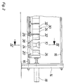
- the system includes two plate-shaped stands 12 and 14, which are firmly connected to one another by two pairs of horizontal, parallel tie rods 16 arranged one above the other.
- the right-hand stand 14 in FIGS. 1 and 2 carries an axial clamping device 18 with a hydraulic piston-cylinder unit, the axis of which is arranged parallel to the tie rods 16 and to the axis A of a longitudinal guide 20.
- the longitudinal guide 20 is formed by a pair of rails which extends between the two stands 12 and 14 and is fastened at regular intervals to the lower pair of tie rods 16 by cross members 22 (FIG. 6).
- Long carriages 24 and short carriages 26 are arranged alternately one behind the other on the longitudinal guide 20.
- the long carriages 24 each have a downward projection 28 for supporting purposes, which will be explained later.
- Casting molds 30 are arranged on the carriages 24 and 26, each of which has two mutually symmetrical side parts 32 and 34, a foot part composed of a foot core 36 and foot ring 38, an upper core 40 (water edge core) and a rear core 42 (rear wall core).
- the base parts 36, 38 each rest on a long carriage 24.
- Side parts 32 and 34 which belong to adjacent molds 30, are fastened in pairs back to back on a short carriage 26; The only exceptions to this are the carriage 26 closest to the stand 12, which only carries a left side part 32, and the carriage 26 closest to the stand 14, which only carries a right side part 34.
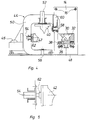
- All casting molds 30 are assigned a common clamping cage 44 which can be moved back and forth by means of its own drive 46 on a horizontal transverse guide 48 at right angles to the axis A between its working position shown in FIG. 3 and its rest position shown in FIGS. 4 and 6 .
- the clamping cage 44 has a plurality of clamping frames 50, each arranged in a plane normal to the axis A, that is to say perpendicular, and firmly connected to one another by longitudinal struts (not shown).
- Each of the casting molds 30 is assigned to one of the clamping frames 50 in such a way that, in the working position of the clamping cage 44, it encompasses the associated casting mold, as shown in FIG. 3.
- each clamping frame 50 Four cross-clamping devices are arranged on each clamping frame 50, namely an upper 52, a rear 54, a lower 56 and a front 58. All cross-clamping devices 52, 54, 56 and 58 each have a hydraulic piston-cylinder unit.
- the purpose of the upper cross-clamping device 52 is to press the upper core 40 downwards during casting and to pull it out after the cast molding 10 has solidified.
- the rear transverse tensioning device 54 acts on the rear core 42 in a corresponding manner.
- the two remaining transverse clamping devices 56 and 58 generate the necessary counterforces by pressing against the shoulder 28 from below or against the side parts 32 and 34 from the front, as long as the associated casting mold 30 is to be held firmly together.
- the front transverse tensioning device 58 is on a leg 60 attached, which is guided vertically displaceably on the associated clamping frame 50 and can be raised and lowered by means of a drive, not shown.
- a leg 60 In the upper end position of the leg 60 (FIGS. 4 and 6) of all the clamping frames 50, the clamping cage 44 can be moved back and forth between its working and its rest position.
- the casting molds 30 consist essentially of porous plastic; however, the upper core 40 and the rear core 42 of each casting mold each have a steel plate on their top and rear sides, which cooperates with an electromagnetic clutch 62 fastened to the associated transverse clamping device 52 and 54, respectively.
- the couplings 62 each have a permanent magnet which is constantly striving to establish a firm connection between the relevant transverse tensioning device 52 and 54 and the associated core 40 and 42 by magnetic attraction of the adjacent steel plate.
- the couplings 62 each have an electromagnet which is polarized so that it cancels the effect of the permanent magnet when excited and thus releases the associated transverse tensioning device 52 or 54 from the core 40 or 42 assigned to it.
- the two stands 12 and 14 are additionally connected to one another by an upper crane runway 64 parallel to the longitudinal guide 20, on which a removal device 66 can be moved.
- the removal device 66 is essentially of a known type and has the task of transferring the moldings 10 produced in the casting molds 30 to a conveyor arranged parallel to the longitudinal guide.
Landscapes
- Engineering & Computer Science (AREA)
- Chemical & Material Sciences (AREA)
- Ceramic Engineering (AREA)
- Dispersion Chemistry (AREA)
- Manufacturing & Machinery (AREA)
- Mechanical Engineering (AREA)
- Moulds, Cores, Or Mandrels (AREA)
- Casting Devices For Molds (AREA)
- Producing Shaped Articles From Materials (AREA)
Applications Claiming Priority (2)
| Application Number | Priority Date | Filing Date | Title |
|---|---|---|---|
| DE4216212A DE4216212C1 (fr) | 1992-05-15 | 1992-05-15 | |
| DE4216212 | 1992-05-15 |
Publications (2)
| Publication Number | Publication Date |
|---|---|
| EP0569855A1 true EP0569855A1 (fr) | 1993-11-18 |
| EP0569855B1 EP0569855B1 (fr) | 1995-09-20 |
Family
ID=6459041
Family Applications (1)
| Application Number | Title | Priority Date | Filing Date |
|---|---|---|---|
| EP93107373A Expired - Lifetime EP0569855B1 (fr) | 1992-05-15 | 1993-05-06 | Installation et procédé pour le coulage sous pression de produits en céramique, en particulier de cuvettes de W.C. |
Country Status (2)
| Country | Link |
|---|---|
| EP (1) | EP0569855B1 (fr) |
| DE (2) | DE4216212C1 (fr) |
Cited By (1)
| Publication number | Priority date | Publication date | Assignee | Title |
|---|---|---|---|---|
| DE19725942A1 (de) * | 1997-06-19 | 1998-12-24 | Sama Maschinenbau Gmbh | Druckgießanlage für Sanitärartikel |
Families Citing this family (4)
| Publication number | Priority date | Publication date | Assignee | Title |
|---|---|---|---|---|
| DE9312232U1 (de) * | 1993-08-16 | 1993-10-28 | Dorst - Maschinen- und Anlagen-Bau Otto Dorst u. Dipl. Ing. Walter Schlegel GmbH & Co, 82431 Kochel | Presse zum Druckgießen keramischer Formlinge |
| IT1268829B1 (it) * | 1994-06-02 | 1997-03-13 | Ideal Standard | Banco automatico di colatura a pressione |
| ITUA20162529A1 (it) * | 2016-04-12 | 2017-10-12 | Siti B & T Group Spa | Linea per la produzione di articoli sanitari |
| IT201900016451A1 (it) * | 2019-09-17 | 2021-03-17 | Siti B & T Group Spa | Attrezzatura per la produzione di articoli sanitari |
Citations (4)
| Publication number | Priority date | Publication date | Assignee | Title |
|---|---|---|---|---|
| DE2065945A1 (de) * | 1969-10-13 | 1977-09-01 | Mansfield Sanitary Inc | Verfahren und eine greifvorrichtung zum wenden einer form fuer keramische gussstuecke |
| EP0332896A1 (fr) * | 1988-03-02 | 1989-09-20 | Toto Ltd. | Dispositif de coulée en bartotine sous pression pour articles céramiques |
| US5083911A (en) * | 1989-08-03 | 1992-01-28 | Toto Ltd. | Pressure slip casting apparatus for producing sanitary ware |
| DE4206279C1 (fr) * | 1992-02-28 | 1993-04-22 | Erich Netzsch Gmbh & Co Holding Kg, 8672 Selb, De |
Family Cites Families (1)
| Publication number | Priority date | Publication date | Assignee | Title |
|---|---|---|---|---|
| DE2445005C3 (de) * | 1974-09-20 | 1980-02-14 | Duravit-Hornberg Sanitaer-Keramisches Werk Gmbh, 7746 Hornberg | Vorrichtung zum Schlickergießen von keramischen Formungen |
-
1992
- 1992-05-15 DE DE4216212A patent/DE4216212C1/de not_active Expired - Fee Related
-
1993
- 1993-05-06 EP EP93107373A patent/EP0569855B1/fr not_active Expired - Lifetime
- 1993-05-06 DE DE59300617T patent/DE59300617D1/de not_active Expired - Fee Related
Patent Citations (4)
| Publication number | Priority date | Publication date | Assignee | Title |
|---|---|---|---|---|
| DE2065945A1 (de) * | 1969-10-13 | 1977-09-01 | Mansfield Sanitary Inc | Verfahren und eine greifvorrichtung zum wenden einer form fuer keramische gussstuecke |
| EP0332896A1 (fr) * | 1988-03-02 | 1989-09-20 | Toto Ltd. | Dispositif de coulée en bartotine sous pression pour articles céramiques |
| US5083911A (en) * | 1989-08-03 | 1992-01-28 | Toto Ltd. | Pressure slip casting apparatus for producing sanitary ware |
| DE4206279C1 (fr) * | 1992-02-28 | 1993-04-22 | Erich Netzsch Gmbh & Co Holding Kg, 8672 Selb, De |
Cited By (2)
| Publication number | Priority date | Publication date | Assignee | Title |
|---|---|---|---|---|
| DE19725942A1 (de) * | 1997-06-19 | 1998-12-24 | Sama Maschinenbau Gmbh | Druckgießanlage für Sanitärartikel |
| DE19725942C2 (de) * | 1997-06-19 | 2001-02-08 | Sama Maschb Gmbh | Druckgießanlage für Sanitärartikel |
Also Published As
| Publication number | Publication date |
|---|---|
| DE59300617D1 (de) | 1995-10-26 |
| EP0569855B1 (fr) | 1995-09-20 |
| DE4216212C1 (fr) | 1993-04-29 |
Similar Documents
| Publication | Publication Date | Title |
|---|---|---|
| EP0557995B1 (fr) | Installation pour le coulage sous pression d'objets en céramique, en particulier de cuvettes de W.C. | |
| EP0569855B1 (fr) | Installation et procédé pour le coulage sous pression de produits en céramique, en particulier de cuvettes de W.C. | |
| DE69729375T2 (de) | Anlage zum Druckgiessen von Sanitärartikeln | |
| EP0666156A1 (fr) | Procédé et dispositif pour séparer les unes des autres des tranches de blocs parallélépipèdiques en béton poreux à l'état encore plastique | |
| EP0896866B1 (fr) | Procédé et dispositif pour la fabrication d'éléments moulés | |
| DE1558281B1 (de) | Druckgiessmaschine | |
| EP0139215B1 (fr) | Coffrage à éléments mobiles pour pièces préfabriquées en béton | |
| DE10242905B4 (de) | Formgusssysteme und -maschinen sowie Kernentnahmeverfahren bei Formgusssystemen und -maschinen | |
| DE2648296A1 (de) | Halte- und tragevorrichtung fuer die giessbleche einer schokoladengiessanlage | |
| DE29801197U1 (de) | Anlage zum Druckgießen keramischer Artikel | |
| DE19725942C2 (de) | Druckgießanlage für Sanitärartikel | |
| DE2166661A1 (de) | Vorrichtung zum herstellen von poren- oder gasbetonbloecken | |
| DE2727257C3 (de) | Niederdruckgießmaschine | |
| DE9010277U1 (de) | Gießformpresse und Modellträger zur Verwendung mit einer solchen Presse | |
| DE2806587C2 (de) | Vorrichtung zum Schlickergießen von keramischen Formungen | |
| DE102023211659A1 (de) | Steinpressmaschine und Verfahren zur Herstellung von Formlingen | |
| DE20022711U1 (de) | Vorrichtung zum Gießen eines Formteils | |
| EP4474077A1 (fr) | Machine de coulée et procédé de coulée d'un produit | |
| DE194432C (fr) | ||
| DE4416182C2 (de) | Spritzgießform zum Herstellen von rohrförmigen Spritzteilen mit Hinterschneidungen | |
| DE19959438B4 (de) | Formmaschine für eine Formherstellung in Formkästen unterschiedlicher Größen | |
| DE3314703C1 (de) | Formrahmenhaltevorrichtung an einer Formmaschine zum Herstellen von kastenlosen Gießformen | |
| DE9204055U1 (de) | Befestigungsklammer | |
| DE1268320B (de) | Einrichtung fuer vertikalen Gussstueckausbau aus Niederdruckgiesswerkzeugen | |
| DE1558281C (fr) |
Legal Events
| Date | Code | Title | Description |
|---|---|---|---|
| PUAI | Public reference made under article 153(3) epc to a published international application that has entered the european phase |
Free format text: ORIGINAL CODE: 0009012 |
|
| AK | Designated contracting states |
Kind code of ref document: A1 Designated state(s): DE ES FR GB IT |
|
| 17P | Request for examination filed |
Effective date: 19931214 |
|
| 17Q | First examination report despatched |
Effective date: 19950224 |
|
| GRAA | (expected) grant |
Free format text: ORIGINAL CODE: 0009210 |
|
| ITF | It: translation for a ep patent filed | ||
| AK | Designated contracting states |
Kind code of ref document: B1 Designated state(s): DE ES FR GB IT |
|
| PG25 | Lapsed in a contracting state [announced via postgrant information from national office to epo] |
Ref country code: FR Effective date: 19950920 Ref country code: ES Free format text: THE PATENT HAS BEEN ANNULLED BY A DECISION OF A NATIONAL AUTHORITY Effective date: 19950920 |
|
| REF | Corresponds to: |
Ref document number: 59300617 Country of ref document: DE Date of ref document: 19951026 |
|
| GBT | Gb: translation of ep patent filed (gb section 77(6)(a)/1977) |
Effective date: 19950928 |
|
| EN | Fr: translation not filed | ||
| PLBE | No opposition filed within time limit |
Free format text: ORIGINAL CODE: 0009261 |
|
| 26N | No opposition filed | ||
| REG | Reference to a national code |
Ref country code: GB Ref legal event code: 732E |
|
| PGFP | Annual fee paid to national office [announced via postgrant information from national office to epo] |
Ref country code: GB Payment date: 20010426 Year of fee payment: 9 |
|
| PGFP | Annual fee paid to national office [announced via postgrant information from national office to epo] |
Ref country code: DE Payment date: 20010613 Year of fee payment: 9 |
|
| REG | Reference to a national code |
Ref country code: GB Ref legal event code: IF02 |
|
| PG25 | Lapsed in a contracting state [announced via postgrant information from national office to epo] |
Ref country code: GB Free format text: LAPSE BECAUSE OF NON-PAYMENT OF DUE FEES Effective date: 20020506 |
|
| PG25 | Lapsed in a contracting state [announced via postgrant information from national office to epo] |
Ref country code: DE Free format text: LAPSE BECAUSE OF NON-PAYMENT OF DUE FEES Effective date: 20021203 |
|
| GBPC | Gb: european patent ceased through non-payment of renewal fee |
Effective date: 20020506 |
|
| PG25 | Lapsed in a contracting state [announced via postgrant information from national office to epo] |
Ref country code: IT Free format text: LAPSE BECAUSE OF NON-PAYMENT OF DUE FEES;WARNING: LAPSES OF ITALIAN PATENTS WITH EFFECTIVE DATE BEFORE 2007 MAY HAVE OCCURRED AT ANY TIME BEFORE 2007. THE CORRECT EFFECTIVE DATE MAY BE DIFFERENT FROM THE ONE RECORDED. Effective date: 20050506 |