EP0569895A1 - Wischer-Antriebsvorrichtung - Google Patents
Wischer-Antriebsvorrichtung Download PDFInfo
- Publication number
- EP0569895A1 EP0569895A1 EP93107514A EP93107514A EP0569895A1 EP 0569895 A1 EP0569895 A1 EP 0569895A1 EP 93107514 A EP93107514 A EP 93107514A EP 93107514 A EP93107514 A EP 93107514A EP 0569895 A1 EP0569895 A1 EP 0569895A1
- Authority
- EP
- European Patent Office
- Prior art keywords
- electric conductor
- clutch member
- driving apparatus
- wiper driving
- movable contact
- Prior art date
- Legal status (The legal status is an assumption and is not a legal conclusion. Google has not performed a legal analysis and makes no representation as to the accuracy of the status listed.)
- Granted
Links
Images



Classifications
-
- B—PERFORMING OPERATIONS; TRANSPORTING
- B60—VEHICLES IN GENERAL
- B60S—SERVICING, CLEANING, REPAIRING, SUPPORTING, LIFTING, OR MANOEUVRING OF VEHICLES, NOT OTHERWISE PROVIDED FOR
- B60S1/00—Cleaning of vehicles
- B60S1/02—Cleaning windscreens, windows or optical devices
- B60S1/04—Wipers or the like, e.g. scrapers
- B60S1/06—Wipers or the like, e.g. scrapers characterised by the drive
- B60S1/16—Means for transmitting drive
-
- B—PERFORMING OPERATIONS; TRANSPORTING
- B60—VEHICLES IN GENERAL
- B60S—SERVICING, CLEANING, REPAIRING, SUPPORTING, LIFTING, OR MANOEUVRING OF VEHICLES, NOT OTHERWISE PROVIDED FOR
- B60S1/00—Cleaning of vehicles
- B60S1/02—Cleaning windscreens, windows or optical devices
- B60S1/04—Wipers or the like, e.g. scrapers
- B60S1/06—Wipers or the like, e.g. scrapers characterised by the drive
- B60S1/08—Wipers or the like, e.g. scrapers characterised by the drive electrically driven
Definitions
- This invention relates to a wiper driving apparatus, and more particularly to improvements in a device for stopping a wiper at a predetermined position, effectively utilized, for example, in a wiper driving apparatus mounted on vehicles such as automobiles which may run in an area of snowfall.
- a device for stopping a wiper at a predetermined position by which a wiper blade is moved to a bottom corner of a window and stopped thereat, even when a switch at hand is turned off at random.
- a conventional device of this type for stopping a wiper at a predetermined position is constructed such that an electric conductor plate including a non-conductive portion in part has been attached to an end face of a drive gear, and a contact is provided in a housing, so as to slide on the electric conductor plate in accordance with rotation of the drive gear, the contact and the electric conductor plate constituting a switch for turning on and off an electric circuit for a motor.
- the wiper driving apparatus having the above-described device for stopping the wiper blade at a predetermined position
- an external force is applied in a direction opposite to the normal rotation of the drive gear, for example, in the case where snow is scraped together to the bottom of the window
- the chattering phenomenon in which conduction and non-conduction are repeated between the electric conductor plate and the contact, occurs.
- the wiper driving apparatus is heated to a considerably high temperature, and is thereby damaged in quality and durability. This is a problem inherent in the conventional wiper driving apparatus.
- a clutch member is rotatably provided for rotating together with a drive gear in a direction that the drive gear is biased to.
- a switch mechanism for turning on and off the electric circuit of the motor which consists of electric conductor plates and the contacts, is interposed between the clutch member and a housing.
- an insulator is used in the clutch member and the clutch member is rotatably provided on a supporting axle of the housing, so that the housing must be formed to increase its height.
- the electric conductor plates are disposed coaxially around a clutch plate, so that the housing must be increased in diameter and in height in order to constitute therein the switch turning on and off the electric circuit of the motor.
- An object of the present invention is to provide a wiper driving apparatus which can facilitate downsizing of the apparatus.
- a wiper driving apparatus comprising: a drive gear rotated by a motor to drive a wiper; a clutch member engageable with said drive gear; a pair of electric conductor plates constituting a switch for turning on and off an electric circuit of said motor; a pair of movable contacts relatively rotatable with said electric conductor plates in sliding contact with said electric conductor plates respectively, said movable contacts being arranged on said clutch member for rotation together with said clutch member; and a housing formed of insulating materials, said housing rotatably supporting said clutch member with an axle, and having said electric conductor plates provided concentrically about said axle, is characterized in that: one of said electric conductor plates which is provided on the inner peripheral side is formed in circular shape and provided adjacently to and around the axle; said clutch member is formed as a conductive member; and one of said movable contacts is formed integrally on said clutch member and said movable contact is sliding contact with said electric conductor plate on the inner peripheral side.
- the clutch member is formed as the conductive member not as the insulator, and therefore, the clutch member is formed integrally with the movable contact.
- the electric conductor plate on the inner peripheral side is provided around the axle of the housing and is in sliding contact with the clutch member. Therefore, it is not necessary to electrically separate the clutch member from the electric conductor plate on the inner peripheral side, so that the respective electric conductor plates can be reduced in diameter.
- the housing can be made decreasing in its thickness by the decrease in the thickness of the clutch member. Accordingly, it is possible to downsize the housing containing therein the switch mechanism for turning on and off the electric circuit of the motor.
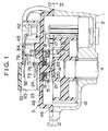
- this wiper driving apparatus comprises a housing 1.
- the housing 1 has a lid member 3 for covering an opening of a main body 2 which forms a gear box, whereby the housing 1 forms therein a tightly closed chamber.
- a driveshaft 4 is rotatably supported at the substantially central portion of the main body 2. As shown in Fig. 5, a link 5 is integrally rotated with the driveshaft 4, and an end of a rod 7 is rotatably connected to a free end of the link 5 through a ball joint 6. The other end of the rod 7 is rotatably connected to a free end of a linkage 8.
- the other end of the linkage 8 is fastened to a shaft 9 which is rotatably supported at a lower position in a window frame of an automobile.
- a wiper arm 10 holding a wiper blade 11 at a free end thereof is supported on the shaft 9 in a manner to be rotatable integrally therewith.
- a drive gear 12 is integrally formed of rigid synthetic resin and coupled to an end portion of the driveshaft 4 in the chamber of the housing 1 in a manner to be rotated integrally with the driveshaft 4.
- An driving engageable portion 13 is projected from an end face on the side of the lid member 3 (hereinafter referred to as the "upper side") of the drive gear 12.
- the lid member 3 is made of an insulating material such as rigid synthetic resin, and integrally formed in a generally triangular dish shape.
- a supporting axle 14 is integrally formed with a ceiling surface of the lid member 3. The supporting axle 14 is projected vertically downwardly in a manner to be aligned in shaft axis with the driveshaft 4.
- a central shaft hole 15a of a clutch member 15 is coupled to the supporting axle 14 to mount the clutch member 15 to the axle 14. Further, a wave washer 20, a flat washer 21 and a stopper ring 22 are coupled successively to the supporting axle 14, whereby the clutch member 15 is positioned between the under surface of the lid member 3 around the supporting axle 14 and the washers 20, 21. Then, in this state, the clutch member 15 is rotatably supported on the supporting axle 14.
- the clutch member 15 is made of a conductive material such as copper.
- the clutch member 15 is integrally formed generally in a short cylindrical shape, in which one end of the cylinder is closed.
- First movable contact 16 is formed to be bulged outwardly in the axial direction of the clutch member 15 around the outer periphery portion of the closed wall of the clutch member 15.
- the first movable contact 16 is formed in a pan shape with hemisphere cross-section, and is urged against an electric conductor plate to be described hereunder, i.e., first electric conductor plate 24 through a suitable resilient force of the first movable contact 16 itself and the wave washer 20.
- a movable contact piece 17 is secured to the clutch member 15 with one end of the movable contact piece 17 being fixed thereto, so as to integrally rotate with the clutch member 15. Then, the movable contact piece 17 and the first movable contact 16 are electrically connected to each other through the clutch member 15 itself.
- the movable contact piece 17 is made of a conductive and suitably resilient plate material such as brass, and punchedly formed to provide a rectangular form in a plane shape. Furthermore, the movable contact piece 17 is somewhat warped in the thicknesswise direction. Because of this warp in cooperation with the resiliency of the movable contact piece 17 itself, second movable contact 18 projected on a free end of the movable contact piece 17 is urged against an electric conductor plate to be described hereunder, i.e., second electric conductor plate 25 through a suitable biasing force.
- An driven engageable portion 19 is vertically downwardly projected toward the drive gear 12 at an end portion of the clutch member 15 on the side of the opening.
- the driven engageable portion 19 is engaged with the driving engageable portion 13 only when the drive gear 12 is normally rotated.
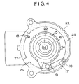
- the first electric conductor plate 24 and the second electric conductor plate 25 are provided to form circles concentrically with the center axis of the supporting axle 14.
- the first and second electric conductor plates are secured to the ceiling surface by a suitable method such as implanting.
- the first electric conductor plate 24 provided at the inner side is formed in a circular shape.
- the first movable contact 16 bulgedly formed on the clutch member 15 is constantly urged to the first electric conductor plate 24 through the resilient force of the first movable contact 16 itself and the wave washer 20 as described above.
- the second electric conductor plate 25 provided at the outer side is formed in a generally C-letter shape, and a cut-away portion thereof forms substantially a non-conductive portion 26.
- a stop position member 27 is formed to provide a generally segmental shape by an electric conductor plate material and disposed in a concentrical circle.
- the second movable contact 18 projected from the clutch member 15 is constantly urged to circular loci drawn by the second electric conductor plate 25, the nonconductive portion 26 and the stop position member 27.
- the motor 31 is provided on one side of the housing 1 in connection therewith.
- a rotary shaft 32 of the motor 31 is inserted into the housing 1 through the main body 2 in a direction perpendicular to the axis of the driveshaft 4.
- a pair of worms (hereinafter may be referred to a "right torsion worm” and a “left torsion worm”) 33 and 34 with torsions opposite to each other are formed on the outer periphery of the inserted portion of the rotary shaft 32 integrally therewith.
- a pair of supporting shafts 35 and 36 are projected in parallel to the driveshaft 4 and located at positions opposed to the worms 33 and 34 respectively, and then at opposite sides of the rotary shaft 32 with each other.
- Worm wheels 37 and 38 are coupled onto and rotatably supported on the supporting shafts 35 and 36 respectively, and are meshed with the worms 33 and 34 respectively.
- Intermediate gears 39 and 40 are center-aligned with the worm wheels 37 and 38 respectively being contiguously and integrally provided thereto. Both of the intermediate gears 39 and 40 are meshed with the drive gear 12.
- the rotation of the motor 31 is transmitted to the drive gear 12 through both of the worms 33 and 34 of the rotary shaft 32, both of the worm wheels 37 and 38, and the intermediate gears 39 and 40.
- the driving engageable portion 13 is engaged with the driven engageable portion 19, to rotate the clutch member 15 together with the drive gear 12.
- the first movable contact 16 and the second movable contact 18, both of which are formed on the clutch member 15 to rotate integrally, are slidably moved along the first electric conductor plate 24 and the second electric conductor plate 25 respectively.
- the first and second movable contacts 16 and 18 remain in contact with the first and second electric conductor plates 24 and 25 as indicated by hypothetical lines in Fig. 5 for example. Namely, current is passed through the power source 29, motor 31, OFF contact of the wiper switch 30, first electric conductor plate 24, first movable contact 16, clutch member 15, movable contact piece 17, second movable contact 18, second electric conductor plate 25 and ground, so that the motor 31 continues to rotate.
- the second movable contact 18 is moved to the stop position member 27 and comes into contact therewith, and a closed circuit is formed through the second movable contact 18, stop position member 27, motor 31, OFF contact of the wiper switch 30, first electric conductor plate 24, first movable contact 16, clutch member 15, movable contact piece 17 and second movable contact 18, so that electric braking is effected to immediately stop the rotation of the motor 31.
- An interrelation of respective component parts is preset so that the wiper blade 11 comes to an home position at the bottom corner of the window when the motor 31 is immediately stopped as described above. Namely, even if the wiper switch 30 is turned off at random, the wiper blade 11 can be always returned to its home position.
- the second electric conductor plate 25 or the second movable contact 18 is arranged to constantly rotate together with the drive gear 12 as in the conventional example, the second movable contact 18, which has been relatively moved to the non-conductive portion 26 due to the normal rotation of the drive gear 12, is relatively returned to the prior position and comes into recontact with the second electric conductor plate 25 because the drive gear 12 is rotated in the reverse direction by a reversely turning force P.
- the clutch member 15 is interposed between the drive gear 12 and the second movable contact 18, so that the above-described chattering phenomenon can be prevented from occurring.
- the drive gear 12 is rotated in the reverse direction because the drive gear 12 is integral with the driveshaft 4.
- the driving engageable portion 13 and the driven engageable portion 19 of the present invention are arranged to disengage from each other when the drive gear 12 is rotated in the reverse direction. Therefore, even when the drive gear 12 is rotated in the reverse direction, the clutch member 15 is not rotated in the reverse direction.
- the clutch member 15 is formed as the conductive member, not as the insulator, and one 16 of the movable contacts is formed integrally on the clutch member 15, so that the first electric conductor plate 24 can be provided adjacently to and around the supporting axle 14. Accordingly, the housing 1 as well as lid member 3 can be produced in small size. Furthermore, the number of parts can be reduced and the number of man-hours to assemble it can be decreased.
- the first movable contact 16 formed on the clutch member 15 itself is arranged to slide on the first electric conductor plate 24, so that, as compared with the conventional apparatus wherein the clutch member 15 is formed of the insulator, the thickness of the lid member 3 of the present invention can be decreased by the thickness of the insulator.
- the lid member 3 is integrally formed with the resin, and the electric conductor plates 24, 25 and 27 are integrally implanted in the lid member 3, so that the thickness of the lid member 3 can be further decreased.
- the number of parts can be reduced and the number of man-hours can be decreased.
- the dimensions of the housing in the diametrical direction and the thicknesswise direction (axial direction) can be reduced, so that a whole size of the wiper driving apparatus can be produced in small size. Further, the number of parts and the number of man-hours can be decreased, thereby enabling to decrease manufacturing costs.
Landscapes
- Engineering & Computer Science (AREA)
- Mechanical Engineering (AREA)
- Connection Of Motors, Electrical Generators, Mechanical Devices, And The Like (AREA)
- Transmission Devices (AREA)
Applications Claiming Priority (2)
| Application Number | Priority Date | Filing Date | Title |
|---|---|---|---|
| JP1992038001U JP2590581Y2 (ja) | 1992-05-11 | 1992-05-11 | ワイパ駆動装置 |
| JP38001/92U | 1992-05-11 |
Publications (2)
| Publication Number | Publication Date |
|---|---|
| EP0569895A1 true EP0569895A1 (de) | 1993-11-18 |
| EP0569895B1 EP0569895B1 (de) | 1996-09-11 |
Family
ID=12513344
Family Applications (1)
| Application Number | Title | Priority Date | Filing Date |
|---|---|---|---|
| EP93107514A Expired - Lifetime EP0569895B1 (de) | 1992-05-11 | 1993-05-07 | Wischer-Antriebsvorrichtung |
Country Status (5)
| Country | Link |
|---|---|
| US (1) | US5422449A (de) |
| EP (1) | EP0569895B1 (de) |
| JP (1) | JP2590581Y2 (de) |
| CA (1) | CA2095310C (de) |
| DE (1) | DE69304598T2 (de) |
Cited By (3)
| Publication number | Priority date | Publication date | Assignee | Title |
|---|---|---|---|---|
| FR2720704A1 (fr) * | 1994-06-07 | 1995-12-08 | Jidosha Denki Kogyo Kk | Interrupteur d'arrêt automatique monté dans un moteur d'essuie-glace. |
| EP1170182A3 (de) * | 2000-07-04 | 2004-04-07 | Asmo Co., Ltd. | Drehpositionssensor und Scheibenwischervorrichtung damit |
| EP2184515A3 (de) * | 2008-11-10 | 2013-06-12 | Robert Bosch GmbH | Getriebe |
Families Citing this family (7)
| Publication number | Priority date | Publication date | Assignee | Title |
|---|---|---|---|---|
| JPH09229666A (ja) * | 1996-02-27 | 1997-09-05 | Asmo Co Ltd | 移動体の位置検出装置 |
| DE19609973A1 (de) * | 1996-03-14 | 1997-09-18 | Teves Gmbh Alfred | Antriebsvorrichtung für Scheibenwischer mit einem Parkstellungsschalter |
| JP3886298B2 (ja) * | 1999-07-12 | 2007-02-28 | 自動車電機工業株式会社 | ワイパモータ |
| US6351088B1 (en) | 2000-03-09 | 2002-02-26 | Valeo Electrical Systems, Inc. | Non-reversing wiper park switch for wiper drive apparatus |
| US6737593B1 (en) | 2000-07-28 | 2004-05-18 | Valeo Electrical Systems, Inc. | Non-reversing windshield wiper motor park switch |
| KR100761056B1 (ko) * | 2006-05-24 | 2007-09-21 | 동양기전 주식회사 | 자동차용 와이퍼 구동장치 |
| CN203410424U (zh) * | 2013-08-20 | 2014-01-29 | 博世汽车部件(长沙)有限公司 | 雨刮电驱动装置及其输出齿轮组件 |
Citations (3)
| Publication number | Priority date | Publication date | Assignee | Title |
|---|---|---|---|---|
| FR2367952A1 (fr) * | 1976-10-16 | 1978-05-12 | Bosch Gmbh Robert | Unite de commande pour dispositifs auxiliaires electriques de vehicules automobiles |
| GB2175493A (en) * | 1985-05-24 | 1986-12-03 | Mitsuba Electric Mfg Co | Wiper drive/switch arrangement |
| EP0359227A2 (de) * | 1988-09-16 | 1990-03-21 | Mitsuba Electric Manufacturing Co., Ltd. | Wischer-Antriebsvorrichtung |
Family Cites Families (8)
| Publication number | Priority date | Publication date | Assignee | Title |
|---|---|---|---|---|
| US3693119A (en) * | 1970-09-25 | 1972-09-19 | Katuhiko Nakama | Electrical timing device |
| JPS59103575U (ja) * | 1982-12-27 | 1984-07-12 | アスモ株式会社 | ワイパモ−タの回転摺動板 |
| JPS6121657A (ja) * | 1984-07-10 | 1986-01-30 | Oki Electric Ind Co Ltd | 回線接続用アダプタ |
| US4613733A (en) * | 1984-10-02 | 1986-09-23 | United Technologies Automotive, Inc. | Delay wiper switch |
| JPS61191960A (ja) * | 1985-02-20 | 1986-08-26 | Sumitomo Light Metal Ind Ltd | 管材または棒材の超音波検査方法 |
| JPS62176068A (ja) * | 1986-01-29 | 1987-08-01 | Showa Denko Kk | 円筒状ポリマ−電池 |
| JPH0513659Y2 (de) * | 1986-04-28 | 1993-04-12 | ||
| JPH074744B2 (ja) * | 1988-07-29 | 1995-01-25 | 株式会社グリーン・システム | 複数作業における適正作業時期決定方法及び装置 |
-
1992
- 1992-05-11 JP JP1992038001U patent/JP2590581Y2/ja not_active Expired - Fee Related
-
1993
- 1993-04-30 CA CA002095310A patent/CA2095310C/en not_active Expired - Fee Related
- 1993-05-07 DE DE69304598T patent/DE69304598T2/de not_active Expired - Fee Related
- 1993-05-07 EP EP93107514A patent/EP0569895B1/de not_active Expired - Lifetime
- 1993-05-11 US US08/060,279 patent/US5422449A/en not_active Expired - Lifetime
Patent Citations (3)
| Publication number | Priority date | Publication date | Assignee | Title |
|---|---|---|---|---|
| FR2367952A1 (fr) * | 1976-10-16 | 1978-05-12 | Bosch Gmbh Robert | Unite de commande pour dispositifs auxiliaires electriques de vehicules automobiles |
| GB2175493A (en) * | 1985-05-24 | 1986-12-03 | Mitsuba Electric Mfg Co | Wiper drive/switch arrangement |
| EP0359227A2 (de) * | 1988-09-16 | 1990-03-21 | Mitsuba Electric Manufacturing Co., Ltd. | Wischer-Antriebsvorrichtung |
Cited By (3)
| Publication number | Priority date | Publication date | Assignee | Title |
|---|---|---|---|---|
| FR2720704A1 (fr) * | 1994-06-07 | 1995-12-08 | Jidosha Denki Kogyo Kk | Interrupteur d'arrêt automatique monté dans un moteur d'essuie-glace. |
| EP1170182A3 (de) * | 2000-07-04 | 2004-04-07 | Asmo Co., Ltd. | Drehpositionssensor und Scheibenwischervorrichtung damit |
| EP2184515A3 (de) * | 2008-11-10 | 2013-06-12 | Robert Bosch GmbH | Getriebe |
Also Published As
| Publication number | Publication date |
|---|---|
| CA2095310C (en) | 2001-12-04 |
| DE69304598D1 (de) | 1996-10-17 |
| DE69304598T2 (de) | 1997-01-23 |
| EP0569895B1 (de) | 1996-09-11 |
| US5422449A (en) | 1995-06-06 |
| CA2095310A1 (en) | 1993-11-12 |
| JPH0589121U (ja) | 1993-12-03 |
| JP2590581Y2 (ja) | 1999-02-17 |
Similar Documents
| Publication | Publication Date | Title |
|---|---|---|
| US4700026A (en) | Wiper home position stop device | |
| US4918272A (en) | Wiper motor driving device for automotive vehicles | |
| US3688332A (en) | Mechanism for opening and closing a cover for a concealed windshield wiper system | |
| US5422449A (en) | Wiper driving apparatus | |
| US4494421A (en) | Windshield wiper driving device | |
| JPH0742889Y2 (ja) | ワイパ駆動装置 | |
| US3881076A (en) | Steering column vehicle switch assembly having rotary and lineal movement | |
| GB2056119A (en) | Wiper device | |
| CA1130063A (en) | Crank arm for a windshield wiper drive mechanism | |
| US3808629A (en) | Actuating mechanism for a depressed park windshield wiper system | |
| JP2000502971A (ja) | ウインドシールドワイパ用ドライブ機構 | |
| DE3606651C2 (de) | ||
| US3059264A (en) | Windshield wiper parking switch | |
| WO2001066388A1 (en) | Non-reversing wiper park switch for wiper drive apparatus | |
| JPH0513659Y2 (de) | ||
| JPH0312603Y2 (de) | ||
| US3132366A (en) | Windshield wiper system | |
| US3691443A (en) | Windshield wiper mechanism | |
| JPH09226526A (ja) | ワイパモータ | |
| JP2004026036A (ja) | 車両用ワイパ装置 | |
| JPS643209Y2 (de) | ||
| DE9414174U1 (de) | Baugruppe für den Antrieb und die Steuerung eines Scheibenwischers in Kraftfahrzeugen | |
| US2670492A (en) | Electric windshield wiper | |
| EP0053425A3 (de) | Aufstellen eines Rückspiegels für Fahrzeuge | |
| JP2607872Y2 (ja) | ワイパモータのオートストップスイッチ |
Legal Events
| Date | Code | Title | Description |
|---|---|---|---|
| PUAI | Public reference made under article 153(3) epc to a published international application that has entered the european phase |
Free format text: ORIGINAL CODE: 0009012 |
|
| AK | Designated contracting states |
Kind code of ref document: A1 Designated state(s): DE FR GB |
|
| 17P | Request for examination filed |
Effective date: 19931123 |
|
| 17Q | First examination report despatched |
Effective date: 19941122 |
|
| GRAG | Despatch of communication of intention to grant |
Free format text: ORIGINAL CODE: EPIDOS AGRA |
|
| GRAH | Despatch of communication of intention to grant a patent |
Free format text: ORIGINAL CODE: EPIDOS IGRA |
|
| GRAH | Despatch of communication of intention to grant a patent |
Free format text: ORIGINAL CODE: EPIDOS IGRA |
|
| RAP1 | Party data changed (applicant data changed or rights of an application transferred) |
Owner name: MITSUBA ELECTRIC MANUFACTURING CO., LTD. |
|
| GRAA | (expected) grant |
Free format text: ORIGINAL CODE: 0009210 |
|
| AK | Designated contracting states |
Kind code of ref document: B1 Designated state(s): DE FR GB |
|
| ET | Fr: translation filed | ||
| REF | Corresponds to: |
Ref document number: 69304598 Country of ref document: DE Date of ref document: 19961017 |
|
| PLBE | No opposition filed within time limit |
Free format text: ORIGINAL CODE: 0009261 |
|
| 26N | No opposition filed | ||
| REG | Reference to a national code |
Ref country code: GB Ref legal event code: IF02 |
|
| PGFP | Annual fee paid to national office [announced via postgrant information from national office to epo] |
Ref country code: GB Payment date: 20040505 Year of fee payment: 12 |
|
| PG25 | Lapsed in a contracting state [announced via postgrant information from national office to epo] |
Ref country code: GB Free format text: LAPSE BECAUSE OF NON-PAYMENT OF DUE FEES Effective date: 20050507 |
|
| GBPC | Gb: european patent ceased through non-payment of renewal fee |
Effective date: 20050507 |
|
| PGFP | Annual fee paid to national office [announced via postgrant information from national office to epo] |
Ref country code: FR Payment date: 20090515 Year of fee payment: 17 Ref country code: DE Payment date: 20090429 Year of fee payment: 17 |
|
| REG | Reference to a national code |
Ref country code: FR Ref legal event code: ST Effective date: 20110131 |
|
| PG25 | Lapsed in a contracting state [announced via postgrant information from national office to epo] |
Ref country code: DE Free format text: LAPSE BECAUSE OF NON-PAYMENT OF DUE FEES Effective date: 20101201 |
|
| PG25 | Lapsed in a contracting state [announced via postgrant information from national office to epo] |
Ref country code: FR Free format text: LAPSE BECAUSE OF NON-PAYMENT OF DUE FEES Effective date: 20100531 |