EP0571093A2 - Tête d'impression à circuit intégré pour imprimante à jet d'encre comprenant un circuit intégré d'identification - Google Patents
Tête d'impression à circuit intégré pour imprimante à jet d'encre comprenant un circuit intégré d'identification Download PDFInfo
- Publication number
- EP0571093A2 EP0571093A2 EP93303399A EP93303399A EP0571093A2 EP 0571093 A2 EP0571093 A2 EP 0571093A2 EP 93303399 A EP93303399 A EP 93303399A EP 93303399 A EP93303399 A EP 93303399A EP 0571093 A2 EP0571093 A2 EP 0571093A2
- Authority
- EP
- European Patent Office
- Prior art keywords
- circuit
- coupled
- resistor
- programmable
- array
- Prior art date
- Legal status (The legal status is an assumption and is not a legal conclusion. Google has not performed a legal analysis and makes no representation as to the accuracy of the status listed.)
- Granted
Links
Images


Classifications
-
- B—PERFORMING OPERATIONS; TRANSPORTING
- B41—PRINTING; LINING MACHINES; TYPEWRITERS; STAMPS
- B41J—TYPEWRITERS; SELECTIVE PRINTING MECHANISMS, i.e. MECHANISMS PRINTING OTHERWISE THAN FROM A FORME; CORRECTION OF TYPOGRAPHICAL ERRORS
- B41J2/00—Typewriters or selective printing mechanisms characterised by the printing or marking process for which they are designed
- B41J2/005—Typewriters or selective printing mechanisms characterised by the printing or marking process for which they are designed characterised by bringing liquid or particles selectively into contact with a printing material
- B41J2/01—Ink jet
- B41J2/17—Ink jet characterised by ink handling
- B41J2/175—Ink supply systems ; Circuit parts therefor
- B41J2/17503—Ink cartridges
- B41J2/17543—Cartridge presence detection or type identification
- B41J2/17546—Cartridge presence detection or type identification electronically
-
- B—PERFORMING OPERATIONS; TRANSPORTING
- B41—PRINTING; LINING MACHINES; TYPEWRITERS; STAMPS
- B41J—TYPEWRITERS; SELECTIVE PRINTING MECHANISMS, i.e. MECHANISMS PRINTING OTHERWISE THAN FROM A FORME; CORRECTION OF TYPOGRAPHICAL ERRORS
- B41J2/00—Typewriters or selective printing mechanisms characterised by the printing or marking process for which they are designed
- B41J2/005—Typewriters or selective printing mechanisms characterised by the printing or marking process for which they are designed characterised by bringing liquid or particles selectively into contact with a printing material
- B41J2/01—Ink jet
- B41J2/015—Ink jet characterised by the jet generation process
- B41J2/04—Ink jet characterised by the jet generation process generating single droplets or particles on demand
- B41J2/045—Ink jet characterised by the jet generation process generating single droplets or particles on demand by pressure, e.g. electromechanical transducers
- B41J2/04501—Control methods or devices therefor, e.g. driver circuits, control circuits
- B41J2/04506—Control methods or devices therefor, e.g. driver circuits, control circuits aiming at correcting manufacturing tolerances
-
- B—PERFORMING OPERATIONS; TRANSPORTING
- B41—PRINTING; LINING MACHINES; TYPEWRITERS; STAMPS
- B41J—TYPEWRITERS; SELECTIVE PRINTING MECHANISMS, i.e. MECHANISMS PRINTING OTHERWISE THAN FROM A FORME; CORRECTION OF TYPOGRAPHICAL ERRORS
- B41J2/00—Typewriters or selective printing mechanisms characterised by the printing or marking process for which they are designed
- B41J2/005—Typewriters or selective printing mechanisms characterised by the printing or marking process for which they are designed characterised by bringing liquid or particles selectively into contact with a printing material
- B41J2/01—Ink jet
- B41J2/015—Ink jet characterised by the jet generation process
- B41J2/04—Ink jet characterised by the jet generation process generating single droplets or particles on demand
- B41J2/045—Ink jet characterised by the jet generation process generating single droplets or particles on demand by pressure, e.g. electromechanical transducers
- B41J2/04501—Control methods or devices therefor, e.g. driver circuits, control circuits
- B41J2/04541—Specific driving circuit
-
- B—PERFORMING OPERATIONS; TRANSPORTING
- B41—PRINTING; LINING MACHINES; TYPEWRITERS; STAMPS
- B41J—TYPEWRITERS; SELECTIVE PRINTING MECHANISMS, i.e. MECHANISMS PRINTING OTHERWISE THAN FROM A FORME; CORRECTION OF TYPOGRAPHICAL ERRORS
- B41J2/00—Typewriters or selective printing mechanisms characterised by the printing or marking process for which they are designed
- B41J2/005—Typewriters or selective printing mechanisms characterised by the printing or marking process for which they are designed characterised by bringing liquid or particles selectively into contact with a printing material
- B41J2/01—Ink jet
- B41J2/015—Ink jet characterised by the jet generation process
- B41J2/04—Ink jet characterised by the jet generation process generating single droplets or particles on demand
- B41J2/045—Ink jet characterised by the jet generation process generating single droplets or particles on demand by pressure, e.g. electromechanical transducers
- B41J2/04501—Control methods or devices therefor, e.g. driver circuits, control circuits
- B41J2/04543—Block driving
-
- B—PERFORMING OPERATIONS; TRANSPORTING
- B41—PRINTING; LINING MACHINES; TYPEWRITERS; STAMPS
- B41J—TYPEWRITERS; SELECTIVE PRINTING MECHANISMS, i.e. MECHANISMS PRINTING OTHERWISE THAN FROM A FORME; CORRECTION OF TYPOGRAPHICAL ERRORS
- B41J2/00—Typewriters or selective printing mechanisms characterised by the printing or marking process for which they are designed
- B41J2/005—Typewriters or selective printing mechanisms characterised by the printing or marking process for which they are designed characterised by bringing liquid or particles selectively into contact with a printing material
- B41J2/01—Ink jet
- B41J2/015—Ink jet characterised by the jet generation process
- B41J2/04—Ink jet characterised by the jet generation process generating single droplets or particles on demand
- B41J2/045—Ink jet characterised by the jet generation process generating single droplets or particles on demand by pressure, e.g. electromechanical transducers
- B41J2/04501—Control methods or devices therefor, e.g. driver circuits, control circuits
- B41J2/04563—Control methods or devices therefor, e.g. driver circuits, control circuits detecting head temperature; Ink temperature
-
- B—PERFORMING OPERATIONS; TRANSPORTING
- B41—PRINTING; LINING MACHINES; TYPEWRITERS; STAMPS
- B41J—TYPEWRITERS; SELECTIVE PRINTING MECHANISMS, i.e. MECHANISMS PRINTING OTHERWISE THAN FROM A FORME; CORRECTION OF TYPOGRAPHICAL ERRORS
- B41J2/00—Typewriters or selective printing mechanisms characterised by the printing or marking process for which they are designed
- B41J2/005—Typewriters or selective printing mechanisms characterised by the printing or marking process for which they are designed characterised by bringing liquid or particles selectively into contact with a printing material
- B41J2/01—Ink jet
- B41J2/015—Ink jet characterised by the jet generation process
- B41J2/04—Ink jet characterised by the jet generation process generating single droplets or particles on demand
- B41J2/045—Ink jet characterised by the jet generation process generating single droplets or particles on demand by pressure, e.g. electromechanical transducers
- B41J2/04501—Control methods or devices therefor, e.g. driver circuits, control circuits
- B41J2/0458—Control methods or devices therefor, e.g. driver circuits, control circuits controlling heads based on heating elements forming bubbles
-
- B—PERFORMING OPERATIONS; TRANSPORTING
- B41—PRINTING; LINING MACHINES; TYPEWRITERS; STAMPS
- B41J—TYPEWRITERS; SELECTIVE PRINTING MECHANISMS, i.e. MECHANISMS PRINTING OTHERWISE THAN FROM A FORME; CORRECTION OF TYPOGRAPHICAL ERRORS
- B41J2/00—Typewriters or selective printing mechanisms characterised by the printing or marking process for which they are designed
- B41J2/005—Typewriters or selective printing mechanisms characterised by the printing or marking process for which they are designed characterised by bringing liquid or particles selectively into contact with a printing material
- B41J2/01—Ink jet
- B41J2/17—Ink jet characterised by ink handling
- B41J2/175—Ink supply systems ; Circuit parts therefor
-
- G—PHYSICS
- G06—COMPUTING OR CALCULATING; COUNTING
- G06K—GRAPHICAL DATA READING; PRESENTATION OF DATA; RECORD CARRIERS; HANDLING RECORD CARRIERS
- G06K19/00—Record carriers for use with machines and with at least a part designed to carry digital markings
- G06K19/06—Record carriers for use with machines and with at least a part designed to carry digital markings characterised by the kind of the digital marking, e.g. shape, nature, code
- G06K19/067—Record carriers with conductive marks, printed circuits or semiconductor circuit elements, e.g. credit or identity cards also with resonating or responding marks without active components
- G06K19/07—Record carriers with conductive marks, printed circuits or semiconductor circuit elements, e.g. credit or identity cards also with resonating or responding marks without active components with integrated circuit chips
-
- B—PERFORMING OPERATIONS; TRANSPORTING
- B41—PRINTING; LINING MACHINES; TYPEWRITERS; STAMPS
- B41J—TYPEWRITERS; SELECTIVE PRINTING MECHANISMS, i.e. MECHANISMS PRINTING OTHERWISE THAN FROM A FORME; CORRECTION OF TYPOGRAPHICAL ERRORS
- B41J2202/00—Embodiments of or processes related to ink-jet or thermal heads
- B41J2202/01—Embodiments of or processes related to ink-jet heads
- B41J2202/17—Readable information on the head
Definitions
- This invention relates generally to ink jet printers and, more particularly, to an integrated circuit for the printhead of the ink jet printer, wherein the integrated circuit contains a resistor array and an identification circuit.
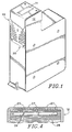
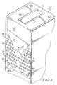
- the print cartridge 10 for an ink jet printer.
- the print cartridge 10 contains ink reservoirs and the integrated circuit (neither are shown in FIG. 1), a printhead 12, a printhead opening or "orifice plate” 11 having a plurality of nozzles for passing a plurality of ink jets, and a flexible "tab" circuit 20 that allows for electrical connection of the printhead 12 to the ink jet printer in which the cartridge 10 is installed.
- Thin film resistors in the integrated circuit resistor array selectively boil ink in the ink reservoir to produce a predetermined ink jet pattern. The placement of the integrated circuit resistor array is best seen in FIG. 3 and is described below.
- the tab circuit 20 is a lead frame type of flexible (“flex") circuit that generally comprises a flexible planar dielectric substrate or film having a metalization pattern formed on one surface thereof by, for example, sputter deposition and photolithographic etching.
- the back side of the flex tab circuit 20 that contains the metalization pattern is bonded to the integrated circuit in the print cartridge 10 using integrated circuit fabrication techniques.
- the front side of the flex tab circuit 20 contains ground pads 25 and interconnect pads 17 for electrical connection to the ink jet printer.
- FIG. 2 is further detail of the orifice plate 11, which is surrounded by insulating adhesive beads 35 for encapsulating the interconnect conductive traces to the integrated circuit in the printhead 12.
- the back side of the flex tab circuit 20 is shown in greater detail in FIG. 3.
- the metalization pattern on the back side of circuit 20 includes conductive traces 13 separated and insulated by predetermined spaces 21.
- the conductive traces 13 connect the integrated circuit (shown generally at 15) to the back side of the interconnect pads 17.
- the printhead 12 of the print cartridge 10 is shown in greater detail in FIG. 4 along perspective lines 4-4 of FIG. 2.
- the simplified cross-sectional of view of FIG. 4 reveals the placement of the integrated circuit 26, which includes the thin film resistor array, in the ink reservoir 28.
- the ink immediately above the integrated circuit 26 is boiled and forced through nozzles 27, forming a pattern of ink jets.
- each print cartridge 10 In an ink jet printer as described above and shown in FIGS. 1-4, it is desirable to have several characteristics of each print cartridge 10 easily identifiable by a controller in the printer. Ideally the data should be supplied directly by the print cartridge 10.
- the "identification data” provides feedback to the controller that adjusts the operation of the printer and ensures correct operation.
- the identified printer characteristics include, but are not limited to, ink color, architecture revision, resolution, number of nozzles 27 in the orifice plate 11, spacing between the nozzles 27, among others.
- Another principal object of the invention is to improve the performance of an integrated circuit printhead in an ink jet printer.
- an integrated circuit for use in the printhead of an ink jet printer includes an array circuit for heating an ink reservoir to produce a pattern of ink jets, the array circuit including a plurality of resistor cells arranged into rows and columns. A corresponding number of row and column lines are coupled to the integrated circuit array for selecting and energizing the resistor cells according to the desired printing pattern.
- An identification circuit integrated into the same substrate as the array circuit includes one or more programmable paths, the programmable paths corresponding and coupled to each row line. The programmable paths each include the serial combination of a programmable fuse and an active device.
- the opposite end of the programmable paths are coupled together at a common node, which in turn is coupled to an output circuit for providing a single serial output signal in response to a sequential polling of the row lines.
- the single serial output can be multiplexed onto an existing interconnect pad in order that the total number of interconnect pads on the print cartridge is not increased.
- the identification signal is multiplexed onto an interconnection pad that is coupled to a thermal resistor divider, which provides analog printhead temperature information.
- the interconnect pad provides analog temperature information within a first voltage range and provides an identification signal in response to the polling of the row lines within a second voltage range.
- the identification circuit provides information to the printer that reveals the type of printhead being used and, with appropriate programming, the type of manufacturing tolerances or defects in the printhead. Programming the identification circuit and polling the row lines does not adversely affect the resistor array or cause the resistor array to heat the ink reservoir and produce ink jets.
- the identification circuit is permanently coupled to the row lines and provides an identification output signal without increasing the number of interconnect pads on the print cartridge.
- FIGS. 1-2 are perspective views of an ink jet print cartridge including a flexible interconnect flex tab circuit.
- FIG. 3 is a plan view of the back side of the flex tab circuit showing a metalization pattern.
- FIG. 4 is a cross-sectional view of a printhead along perspective lines 4-4 of FIG. 2.
- FIG. 5 is a block diagram of the ink jet printer showing the identification circuit according to the present invention and the key electrical blocks in communication with the identification.
- FIG. 6 is a block diagram of the resistor array circuit.
- FIG. 7 is a schematic diagram of one of the resistor cells in the array circuit.
- FIG. 8 is a plot of the controller bus and drive line waveforms.
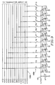
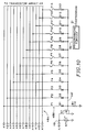
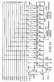
- FIGS. 9-11 are schematic diagrams of three embodiments of the identification circuit of the present invention.
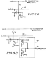
- FIGS. 9A and 9B are schematic diagrams of pulldown and programming circuits suitable for use in the embodiment of FIG. 9.
- the identification circuit 45 and key electrical circuits 42, 43, 44, and 46 are shown in block diagram form.
- a microprocessor controller 42 such as a Motorola MC 68000 sends digital data to the head drive circuitry 43 over digital busses 47A-47C.
- digital bus 47A is an encoded four bit address bus that contains the row addresses for selecting a row of resistor cells in the array circuit 44.
- Digital busses 47B and 47C are encoded eight bit "primitive" busses that contain the column addresses and timing information for selecting a particular resistor cell within a particular row of resistor cells.
- busses 47A-47C The number of row and column addresses handled by busses 47A-47C is related to the total number of resistors in the array circuit 44 that must be individually addressed. When decoded, the number must be equal to or greater than the total number of resistors in the array circuit 44.
- the digital information carried by the digital busses 47A-47C is converted into analog pulses on drive lines 48A by the head drive circuitry 43. Only the address (row) drive lines 48A are shown in FIG. 5.
- the head drive circuitry 43 includes demultiplexing, level shifting, and output buffering to generate the appropriate analog pulses.
- the analog pulses are of sufficient duration and energy to heat the resistor cells in the array circuit 44 and boil the ink between the array circuit 44 and orifice plate 11.
- the time and voltage of the pulses varies and is matched to the design of the printhead used.
- the waveforms for the digital busses 47A-47C and the drive lines 48A are shown in FIG. 8.
- the address and primitive bus waveforms are typical digital signals, switching between zero and five volts.
- the address bus waveform is stable for a fixed time before and after the primitive bus waveform, typically between one and seven microseconds.
- the row and column drive signals are typically between eight and sixteen volts, the exact voltage being dependent upon the type of resistor array circuit used.
- the printhead 41 includes the resistor array circuit 44, an integrated identification circuit 45, and a temperature sense circuit 46.
- the analog drive pulses are received by the resistor array circuit 44 through drive lines 48A to initiate the printing action described above.
- Also coupled to the address drive lines 48A are corresponding input lines 48B, which are in turn coupled to the inputs of the identification circuit 45.
- An integrated temperature sense circuit 46 is also integrated onto the same integrated circuit as the array and identification circuits 44 and 45, in order to supply temperature data to the controller 42.
- the output of the identification circuit 45 and the temperature sense circuit are multiplexed together, thus sharing a single, existing interconnection pad.
- the single output containing the identification and temperature data is supplied to the controller 42 through data output line 49.
- the structure of the array circuit 44 is shown in greater detail in FIG. 6.
- the integrated array circuit 44 for heating the ink reservoir includes a plurality of resistor cells 39 arranged in a predetermined number of rows and columns, depending upon the desired resolution of the ink jet printer.
- a plurality of row lines (address lines A0 through A5) and column lines (primitive lines P0 through P5) are coupled to the integrated circuit array 44 for selecting one of the resistor cells 39. Again, the total number of row and column lines is selected for illustration purposes, only. The actual number can be more or less depending upon the application. In some cases, the number of primitive lines is seven.
- a resistor cell 39 is shown in greater detail in FIG. 7.
- Each resistor cell includes a field-effect transistor 34 for controlling current flow through the resistor 33.
- the resistor 33 is desirably a thin film resistor such as Tantalum Aluminum (TaAl).
- the resistor 33 is sized to provide sufficient thermal energy to boil the ink in the ink reservoir.
- the field-effect transistor is coupled between one end of the resistor 33 and ground, with the gate being coupled to a representative row line A N .
- the other end of the resistor 33 is coupled to a representative column line P M .
- the address drive lines 48A are shown including individual drive lines A1 through A13.
- the number of drive lines is, of course, dependent upon the number of rows of resistor cells 39 in the array circuit 44.
- the exact number in FIG. 9 is for illustration only.
- the identification circuit 45 further includes a plurality of programmable paths corresponding and coupled to each address (row) line 48A through input lines 48B.
- the programmable paths each include the serial combination of a programmable fuse and an active device.
- the programmable fuse is either mask programmable, a fusible link, or other type of fuse in series with the gate of a field-effect transistor.
- Fuses F1-F5 are typically mask programmed at the time the print cartridge 10 is manufactured.
- Programmable fuses F6-F13 are fabricated out of polysilicon or other suitable materials and are typically programmed by a programming circuit (seen in FIG. 9B and discussed below) after the cartridge is manufactured.
- the active device is a typically a field-effect transistor (Q1-Q13).
- the programmable path in series with the gates of transistors Q1-Q13 are programmed to make a connection to the address lines 48A to establish a digital code.
- the digital code generated by transistors Q1-Q13 provides information to the ink jet printer as to the type of print cartridge that is installed and other information related to manufacturing tolerances and defects.
- fuses F1-F5 are depicted in an undefined (either logic one or zero) logic state
- fuses F6-F13 are depicted in an unprogrammed state (either all logic one or logic zero, depending upon the convention chosen.)
- the second end of the programmable paths (in FIG. 9 the second end of the programmable paths is the drain of transistors Q1-Q13) are coupled together at node 49.
- Node 49 forms a single output signal in response to a polling of the address lines 48A.
- Node 49 is a coupled to an output circuit, which is simply a pull-up resistor (not shown in FIG. 9) coupled to a positive power supply in the ink jet printer.
- FIG. 9A a pulldown transistor QPD1 is shown having a shorted drain and gate coupled to the gate corresponding transistor Q1.
- the source of transistor QPD1 is coupled to ground. While only one such pulldown transistor is shown, each transistor Q1 through Q13 includes a corresponding pulldown transistor.
- the pulldown transistor is necessary to pulldown the gate of transistor Q1 through Q13 if the corresponding fuse is opened. If the pulldown transistor is omitted, the gate of transistors Q1 through Q13 will float, placing the transistor, and A/D 49 node, in an indeterminate logic state.
- Figure 9B shows additional circuit detail for programming fuses F6 through F13. Since fuses F6 through F13 are not mask-programmable, an additional current pulse from a programming circuit is used to program the fuse.
- Programming circuit 50 has an input 51 designated PROGRAM and an output coupled to the gate of transistor Q6.
- Programming circuit 50 includes a programming transistor QPROG6 and a pulldown transistor QPPD. The drain of transistor QPROG6 forms the output of the programming circuit 50.
- the gate of transistor QPROG6 is coupled to the drain and gate of transistor QPPD to form the input 51 of programming circuit 50. The sources of both transistors are coupled to ground.
- the programming circuit will have eight outputs and eight programming transistors QPROG6 through QPROG13.
- the gates of each of the programming transistors is coupled to the common input line 51 for receiving the PROGRAM input signal. Only one pulldown transistor QPPD, however, need be used, regardless of the number of outputs. The pulldown transistor QPPD assures that the all outputs of the programming circuit 50 are off when the PROGRAM input signal is low or an open circuit.
- the programming circuit 50 is activated by supplying a logic high PROGRAM signal on input line 51.
- a particular address line A N By selecting a particular address line A N , an extra current flows through the corresponding programming transistor sufficient to program (open) the fuse. Fuses coupled to unselected address lines remain unprogrammed (short circuited).
- input line 51 represents an extra input pin for the printhead, it is not necessary that input line 51 be grouped with the existing printer connector pads (best seen in FIG. 2).
- the extra input line connector pad can be placed anywhere on the printhead.
- a special programming fixture can be built to interface with the extra connector pad. It may desirable to place the programming connector pad away from the main group of printer connector pads to avoid an inadvertent entry into the programming mode.
- a polling of the address line turns on the transistor and pulls node 49 low.
- a polling of the address line has no effect on the turned off transistor, since the gate is pulled low, and node 49 remains high.
- the signal on node 49 is a serial data output corresponding to the data code formed polling the address lines coupled to the programmable paths of the identification circuit 45.
- the identification signal output at node 49 is coupled to a thermal resistor RT1, which forms a resistor divider with a pull-up resistor (not shown in FIG. 9) between V cc and ground.
- the value of the thermal resistor is set to provide a suitable voltage ratio, as explained below.
- a typical example of desirable values for the thermal resistor and pull-up resistor are 422 ohms each.
- the 422 ohm value is standard for a 1% resistor, but other values can be used for each resistor, and the resistor values need not be the same.
- V cc equal to five volts and resistance values being equal, however, the ratio of resistor values sets a nominal voltage at node 49 of 2.5 volts.
- Analog information relating to the printhead temperature and digital information relating to the identification code are multiplexed together in order that an additional interconnect pad is not needed.
- the output signal at node 49 provides analog temperature information within a first voltage range of about two volts at 0° C to about four volts at 100° C.
- the same output node provides an output identification signal in response to the polling of the address lines 48A within a second voltage range.
- Output node 49 falls to about one volt or less when an address line A N is polled and the corresponding programmable path has been previously programmed to form a connection to the gate of the associated transistor Q N .
- the one volt signal can therefore be used as a logic zero. If the programmable path has been previously programmed to form an open circuit, the preexisting analog temperature voltage does not change.
- the two to four voltage temperature voltage can therefore be used as a logic one.
- the output portion of the identification circuit includes a resistor R1 and field-effect transistor Q1 coupled to the common node 49'.
- Resistor R1 is desirably a polysilicon resistor having a value of 1K ohms, but can be made in a manner suitable to an integrated circuit process such as NiCr resistors or self-biased FETs.
- a signal voltage is developed across resistor R1 in response to current flow through any of the diodes D1-D13 that are programmably coupled to the address lines. The signal voltage is in turn coupled to the gate of the transistor Q1.
- Transistor Q1 turns on and off in response to current flow in the programmable paths in a similar fashion to the transistors Q1-Q13 as described in the embodiment of FIG. 9. Diodes D1-D13 are necessary for current steering.
- a programming circuit 50 having a single programming transistor and a single pulldown transistor has an input 51 for receiving the PROGRAM input signal and a single output coupled to common node 49'.
- FIG. 11 Another alternative embodiment of identification circuit 45 is shown in FIG. 11. This embodiment is similar to the embodiment of FIG. 10, except that two programmable paths are used for each address line. For example, a programmable path that includes diode D13 and D26 is coupled to address line A1. The embodiment of FIG. 11 is desirable if more bits are needed in the identification signal. Rather than a single output transistor, the identification circuit 45 of FIG. 11 includes transistors Q1 and Q2, the gate of which is coupled to a respective row of diodes. The drains of transistors Q1 and Q2 are coupled together to form a single output that is multiplexed with the analog temperature information at node 49. The source of transistors Q1 and Q2 are respectively coupled to the drain of transistor Q3 and Q4.
- Primitive signals P0 and P1 turn on either transistor Q3 or Q4, and thus enable either transistor Q1 or transistor Q2 to pass the identification signal to the output node 49.
- the pulse width of the primitive signals P0 and P1 are desirable that the pulse width of the primitive signals P0 and P1 not be extended beyond the normal pulse width.
- Separate programming circuits 50A and 50B are provided to program each set of transistors.
- the fuses are programmed according to a predetermined pattern.
- Part of the pattern can be programmed at preassembly (through mask programmable fuses) to identify the print cartridge and part of the pattern can be programmed after the print cartridge is assembled (through integrated current programmable fuses) to provide compensation information to the controller.
- Programming the fuses includes the step of forming an open-circuit path between an address line and an active device in response to a logic high signal impressed on the selected address line and a current pulse from a programming circuit. A short-circuit path remains coupled to the unselected address lines.
- each row line can be polled to ascertain the identification data. If the primitive connections to the resistor array circuit are disconnected or the primitive voltage pulses are not used, no power is consumed in the resistor array and the address polling pulses can be as long as desired. Otherwise, short address polling pulses are desirably used that are not of sufficient duration to cause significant heating in the resistor array.
- the polling of the row lines causes a signal current to flow through the programmable paths that are programmed in a first logic state (short circuit) and no current to flow through the programmable paths that are programmed in a second logic state (open circuit).
- the signal currents of the programmable paths are combined to form a single serial output identification signal. If desired, the output identification signal can be multiplexed onto an existing interconnection pad of the printhead, such as the thermal resistor divider circuit described above.
- the programming circuit may be eliminated entirely, and non-current programmed fuses such as laser ablated fuses may be used. Also, fuses may be omitted during the fabrication process and connections created or grown as needed. We therefore claim all modifications and variation coming within the spirit and scope of the following claims.
Landscapes
- Engineering & Computer Science (AREA)
- Computer Hardware Design (AREA)
- Microelectronics & Electronic Packaging (AREA)
- Physics & Mathematics (AREA)
- General Physics & Mathematics (AREA)
- Theoretical Computer Science (AREA)
- Particle Formation And Scattering Control In Inkjet Printers (AREA)
- Ink Jet (AREA)
- Bus Control (AREA)
Applications Claiming Priority (2)
| Application Number | Priority Date | Filing Date | Title |
|---|---|---|---|
| US07/886,641 US5363134A (en) | 1992-05-20 | 1992-05-20 | Integrated circuit printhead for an ink jet printer including an integrated identification circuit |
| US886641 | 1992-05-20 |
Publications (3)
| Publication Number | Publication Date |
|---|---|
| EP0571093A2 true EP0571093A2 (fr) | 1993-11-24 |
| EP0571093A3 EP0571093A3 (fr) | 1995-07-19 |
| EP0571093B1 EP0571093B1 (fr) | 1998-09-16 |
Family
ID=25389441
Family Applications (1)
| Application Number | Title | Priority Date | Filing Date |
|---|---|---|---|
| EP93303399A Expired - Lifetime EP0571093B1 (fr) | 1992-05-20 | 1993-04-30 | Tête d'impression à circuit intégré pour imprimante à jet d'encre comprenant un circuit intégré d'identification |
Country Status (4)
| Country | Link |
|---|---|
| US (1) | US5363134A (fr) |
| EP (1) | EP0571093B1 (fr) |
| JP (1) | JP3428683B2 (fr) |
| DE (1) | DE69321028T2 (fr) |
Cited By (37)
| Publication number | Priority date | Publication date | Assignee | Title |
|---|---|---|---|---|
| WO1996005061A1 (fr) * | 1994-08-09 | 1996-02-22 | Encad, Inc. | Cartouche d'encre pour imprimante |
| US5610635A (en) * | 1994-08-09 | 1997-03-11 | Encad, Inc. | Printer ink cartridge with memory storage capacity |
| EP0765762A1 (fr) * | 1995-09-27 | 1997-04-02 | Lexmark International, Inc. | Circuit pour l'identification d'une tête d'imprimante à jet d'encre, avec une connexion sérielle et un registre à décalage dynamique |
| EP0780236A1 (fr) * | 1995-12-20 | 1997-06-25 | Canon Kabushiki Kaisha | Dispositif d'enregistrement avec une tête d'enregistrement identifiable et tête d'enregistrement ayant une fonction identifiable |
| US5646660A (en) * | 1994-08-09 | 1997-07-08 | Encad, Inc. | Printer ink cartridge with drive logic integrated circuit |
| US5757394A (en) * | 1995-09-27 | 1998-05-26 | Lexmark International, Inc. | Ink jet print head identification circuit with programmed transistor array |
| EP0819533A3 (fr) * | 1996-07-12 | 1998-11-25 | Canon Kabushiki Kaisha | Procédé de standardisation d'une tête d'enregistrement à jet d'encre et tête d'enregistrement à jet d'encre pour atteindre une telle standardisation, procédé d'enregistrement à jet d'encre, appareil de traitement d'information et appareil hÔte |
| EP0927639A3 (fr) * | 1997-12-29 | 1999-10-27 | Canon Kabushiki Kaisha | Dispositif d'impression et procédé d'impression |
| EP0916503A3 (fr) * | 1997-11-14 | 2000-05-03 | Canon Kabushiki Kaisha | Tête, appareil d'enregistrement possédant cette tête, méthode pour identifier la tête et méthode pour transmettre à la tête les informations d'identification |
| EP0997280A3 (fr) * | 1998-10-27 | 2000-09-27 | Canon Kabushiki Kaisha | Substrat de tête d'impression ayant une mémoire de données, tête d'impression, appareil d'impression et méthode pour les produire |
| EP0980758A3 (fr) * | 1998-08-19 | 2000-11-22 | Canon Kabushiki Kaisha | Tête d'impression, cartouche comportant cette tête, appareil d'impression utilisant cette tête et substrat de la tête d'impression |
| EP1016524A3 (fr) * | 1998-12-28 | 2000-11-22 | Canon Kabushiki Kaisha | Tête d'impression, appareil d'impression et méthode de commande de tête d'impression |
| EP0933211A3 (fr) * | 1998-01-28 | 2000-12-20 | Neopost Limited | Enregistrement des données d'une tête d'impression numérique |
| EP1079326A2 (fr) | 1999-08-24 | 2001-02-28 | Canon Kabushiki Kaisha | Traitement de données d'impression pour imprimer avec une tête d'impression spécifique |
| US6227643B1 (en) * | 1997-05-20 | 2001-05-08 | Encad, Inc. | Intelligent printer components and printing system |
| EP1004443A3 (fr) * | 1998-10-27 | 2001-07-25 | Canon Kabushiki Kaisha | Substrat de tête, tête à jet d'encre, et imprimante à jet d'encre |
| EP1219437A3 (fr) * | 2000-12-26 | 2002-11-06 | Seiko Epson Corporation | Bornes pour circuit imprimé |
| EP1174277A3 (fr) * | 2000-07-19 | 2003-07-02 | Hewlett-Packard Company | Techniques pour augmenter l'information d'identification d'une tête à jet d'encre dans un environnement de liaisons limitées |
| EP1445110A3 (fr) * | 1998-05-18 | 2004-11-17 | Seiko Epson Corporation | Appareil d'impression à jet d'encre et cartouche d'encre correspondante |
| US6866359B2 (en) | 2001-01-09 | 2005-03-15 | Eastman Kodak Company | Ink jet printhead quality management system and method |
| WO2005044572A3 (fr) * | 2003-10-31 | 2005-07-21 | Hewlett Packard Development Co | Circuit d'interconnexion |
| WO2005044571A3 (fr) * | 2003-10-31 | 2005-07-21 | Hewlett Packard Development Co | Circuit d'interconnexion |
| WO2005105451A3 (fr) * | 2004-04-19 | 2006-03-23 | Hewlett Packard Development Co | Dispositif d'injection de liquide comprenant des cellules d'identification |
| EP1466741A3 (fr) * | 1998-05-13 | 2006-05-24 | Seiko Epson Corporation | Cartouche d'encre pour imprimante à jet d'encre |
| US7101029B2 (en) | 2003-10-31 | 2006-09-05 | Hewlett-Packard Development Company, L.P. | Interconnect circuit |
| EP1719625A1 (fr) * | 2005-04-22 | 2006-11-08 | Canon Kabushiki Kaisha | Tête d'impression par jet d'encre et imprimante l'utilisant |
| EP1785278A1 (fr) * | 1999-10-04 | 2007-05-16 | Seiko Epson Corporation | Appareil d'enregistrement à jet d'encre, dispositif semi-conducteur et appareil doté d'une tête d'enregistrement |
| EP0997033B1 (fr) * | 1997-07-15 | 2007-09-05 | Silverbrook Research Pty. Limited | Systeme d'appareil photographique jetable rechargeable |
| US7309120B2 (en) | 2004-06-02 | 2007-12-18 | Canon Kabushiki Kaisha | Head substrate, printhead, head cartridge, printing apparatus, and method for inputting/outputting information |
| US7364284B2 (en) | 2004-06-02 | 2008-04-29 | Canon Kabushiki Kaisha | Head substrate, printhead, head cartridge, and printing apparatus |
| RU2341378C2 (ru) * | 2002-06-17 | 2008-12-20 | Сейко Эпсон Корпорейшн | Струйное печатающее устройство и картридж с чернилами |
| US7553002B2 (en) | 2002-10-30 | 2009-06-30 | Samsung Electronics Co., Ltd. | Ink-jet printhead |
| EP2216179A3 (fr) * | 2001-04-03 | 2010-11-24 | Seiko Epson Corporation | Cartouche d'encre, appareil d'enregistrement à jet d'encre et jeu de cartouches d'encre |
| EP2073983A4 (fr) * | 2006-10-09 | 2012-08-01 | Silverbrook Res Pty Ltd | Circuit intégré de tête d'impression avec test d'actionneur ouvert |
| EP2551115A1 (fr) * | 2011-07-27 | 2013-01-30 | Brother Kogyo Kabushiki Kaisha | Cartouche liquide et dispositif d'enregistrement d'images |
| EP2543513A3 (fr) * | 2011-07-06 | 2013-02-27 | Ricoh Company, Ltd. | Tête d'impression à jet d'encre, dispositif d'impression à jet d'encre et appareil de fabrication de la tête d'impression à jet d'encre |
| US8801161B2 (en) | 2011-07-27 | 2014-08-12 | Brother Kogyo Kabushiki Kaisha | Liquid cartridge, image recording device, and substrate |
Families Citing this family (135)
| Publication number | Priority date | Publication date | Assignee | Title |
|---|---|---|---|---|
| US5455611A (en) * | 1992-05-29 | 1995-10-03 | Scitex Digital Printing, Inc. | Four inch print head assembly |
| US5504507A (en) * | 1992-10-08 | 1996-04-02 | Xerox Corporation | Electronically readable performance data on a thermal ink jet printhead chip |
| US5691750A (en) * | 1992-11-24 | 1997-11-25 | Lexmark International, Inc. | Ink level sensing for disposable ink jet print head cartridges |
| EP0622207B1 (fr) * | 1993-04-30 | 1999-06-02 | Hewlett-Packard Company | Plate-forme commune pour cartouche à jet d'encre pour têtes d'impression différentes |
| EP0626266B1 (fr) | 1993-05-27 | 2002-03-13 | Canon Kabushiki Kaisha | Appareil d'enregistrement commandé par les caractéristiques de la tête et méthode d'enregistrement |
| US5635968A (en) * | 1994-04-29 | 1997-06-03 | Hewlett-Packard Company | Thermal inkjet printer printhead with offset heater resistors |
| US6382764B1 (en) * | 1994-07-29 | 2002-05-07 | Canon Kabushiki Kaisha | Printing method and apparatus for counting number of ejected ink droplets for controlling printhead recovery |
| US5627572A (en) * | 1994-10-24 | 1997-05-06 | Lexmark International, Inc. | Programmable head type detection and maintenance system |
| US5699091A (en) * | 1994-12-22 | 1997-12-16 | Hewlett-Packard Company | Replaceable part with integral memory for usage, calibration and other data |
| US6325479B1 (en) * | 1995-02-06 | 2001-12-04 | Canon Kabushiki Kaisha | Ink jet recording apparatus, electronic apparatus using the same and change control method therefor |
| JPH0911527A (ja) * | 1995-06-29 | 1997-01-14 | Tec Corp | 記録装置 |
| US6022094A (en) * | 1995-09-27 | 2000-02-08 | Lexmark International, Inc. | Memory expansion circuit for ink jet print head identification circuit |
| US5831649A (en) * | 1996-05-17 | 1998-11-03 | Xerox Corporation | Thermal ink jet printing system including printhead with electronically encoded identification |
| US6081280A (en) * | 1996-07-11 | 2000-06-27 | Lexmark International, Inc. | Method and apparatus for inhibiting electrically induced ink build-up on flexible, integrated circuit connecting leads, for thermal ink jet printer heads |
| US5942900A (en) * | 1996-12-17 | 1999-08-24 | Lexmark International, Inc. | Method of fault detection in ink jet printhead heater chips |
| US6786420B1 (en) | 1997-07-15 | 2004-09-07 | Silverbrook Research Pty. Ltd. | Data distribution mechanism in the form of ink dots on cards |
| US5877798A (en) * | 1997-03-21 | 1999-03-02 | Lexmark International Inc. | Method and apparatus for automatically determining the style printhead installed in a laser printer |
| JPH115334A (ja) * | 1997-04-23 | 1999-01-12 | Canon Inc | 印刷装置及びその制御方法及び前記印刷装置を接続する情報処理装置及びシステム及び記憶媒体 |
| US6137008A (en) * | 1997-05-14 | 2000-10-24 | National Science Council | Flexible diamine compound for preparation of polyamide and polyimide |
| US6618117B2 (en) | 1997-07-12 | 2003-09-09 | Silverbrook Research Pty Ltd | Image sensing apparatus including a microcontroller |
| US20040119829A1 (en) | 1997-07-15 | 2004-06-24 | Silverbrook Research Pty Ltd | Printhead assembly for a print on demand digital camera system |
| US7110024B1 (en) | 1997-07-15 | 2006-09-19 | Silverbrook Research Pty Ltd | Digital camera system having motion deblurring means |
| US6879341B1 (en) | 1997-07-15 | 2005-04-12 | Silverbrook Research Pty Ltd | Digital camera system containing a VLIW vector processor |
| US6624848B1 (en) | 1997-07-15 | 2003-09-23 | Silverbrook Research Pty Ltd | Cascading image modification using multiple digital cameras incorporating image processing |
| US6312070B1 (en) * | 1997-07-15 | 2001-11-06 | Silverbrook Research Pty Ltd | Recycling of multi—use digital instant printing camera systems |
| US6690419B1 (en) | 1997-07-15 | 2004-02-10 | Silverbrook Research Pty Ltd | Utilising eye detection methods for image processing in a digital image camera |
| US6467867B1 (en) * | 1997-09-03 | 2002-10-22 | Macdermid Acumen, Inc. | Method and apparatus for registration and color fidelity control in a multihead digital color print engine |
| US6290333B1 (en) | 1997-10-28 | 2001-09-18 | Hewlett-Packard Company | Multiple power interconnect arrangement for inkjet printhead |
| US6154229A (en) | 1997-10-28 | 2000-11-28 | Hewlett-Packard Company | Thermal ink jet print head and printer temperature control apparatus and method |
| US6575548B1 (en) | 1997-10-28 | 2003-06-10 | Hewlett-Packard Company | System and method for controlling energy characteristics of an inkjet printhead |
| US6536871B1 (en) * | 1997-11-05 | 2003-03-25 | Hewlett-Packard Company | Reliable flex circuit interconnect on inkjet print cartridge |
| DE19752938C2 (de) * | 1997-11-28 | 2000-05-31 | Pelikan Produktions Ag Egg | Umkodierung von Tintendruckköpfen |
| US6099101A (en) * | 1998-04-06 | 2000-08-08 | Lexmark International, Inc. | Disabling refill and reuse of an ink jet print head |
| JPH11300965A (ja) * | 1998-04-24 | 1999-11-02 | Brother Ind Ltd | インクジェットヘッドの駆動調整方法 |
| US6264301B1 (en) * | 1998-05-11 | 2001-07-24 | Hewlett-Packard Company | Method and apparatus for identifying parameters in a replaceable printing component |
| JP3664218B2 (ja) * | 1998-05-25 | 2005-06-22 | セイコーエプソン株式会社 | インクジェット記録装置、及びインクカートリッジ |
| US6161915A (en) * | 1998-06-19 | 2000-12-19 | Lexmark International, Inc | Identification of thermal inkjet printer cartridges |
| US6276777B1 (en) * | 1998-07-21 | 2001-08-21 | Hewlett-Packard Company | Variable maximum operating temperature for a printhead |
| ATE475537T1 (de) * | 1998-08-31 | 2010-08-15 | Seiko Epson Corp | Druckvorrichtung und druckkopfeinheit |
| AUPP702098A0 (en) | 1998-11-09 | 1998-12-03 | Silverbrook Research Pty Ltd | Image creation method and apparatus (ART73) |
| US6116717A (en) * | 1998-09-15 | 2000-09-12 | Lexmark International, Inc. | Method and apparatus for customized control of a print cartridge |
| US6151041A (en) * | 1998-10-19 | 2000-11-21 | Lexmark International, Inc. | Less restrictive print head cartridge installation in an ink jet printer |
| US6755495B2 (en) | 2001-03-15 | 2004-06-29 | Hewlett-Packard Development Company, L.P. | Integrated control of power delivery to firing resistors for printhead assembly |
| US6435668B1 (en) | 1999-02-19 | 2002-08-20 | Hewlett-Packard Company | Warming device for controlling the temperature of an inkjet printhead |
| US6729707B2 (en) * | 2002-04-30 | 2004-05-04 | Hewlett-Packard Development Company, L.P. | Self-calibration of power delivery control to firing resistors |
| US6705694B1 (en) | 1999-02-19 | 2004-03-16 | Hewlett-Packard Development Company, Lp. | High performance printing system and protocol |
| US6318828B1 (en) | 1999-02-19 | 2001-11-20 | Hewlett-Packard Company | System and method for controlling firing operations of an inkjet printhead |
| US6476928B1 (en) | 1999-02-19 | 2002-11-05 | Hewlett-Packard Co. | System and method for controlling internal operations of a processor of an inkjet printhead |
| AUPQ056099A0 (en) | 1999-05-25 | 1999-06-17 | Silverbrook Research Pty Ltd | A method and apparatus (pprint01) |
| US6299292B1 (en) | 1999-08-10 | 2001-10-09 | Lexmark International, Inc. | Driver circuit with low side data for matrix inkjet printhead, and method therefor |
| US6325481B1 (en) * | 1999-08-13 | 2001-12-04 | Hewlett-Packard Company | Method and apparatus for pen temperature control in a thermal printer |
| US6318846B1 (en) | 1999-08-30 | 2001-11-20 | Hewlett-Packard Company | Redundant input signal paths for an inkjet print head |
| US7019866B1 (en) | 1999-08-30 | 2006-03-28 | Hewlett-Packard Development Company, L.P. | Common communication bus and protocol for multiple injet printheads in a printing system |
| US6309040B1 (en) | 1999-09-03 | 2001-10-30 | Hewlett-Packard Company | Signaling method for a pen driver circuit interface |
| US6263170B1 (en) | 1999-12-08 | 2001-07-17 | Xerox Corporation | Consumable component identification and detection |
| EP1138489A1 (fr) * | 2000-03-24 | 2001-10-04 | Seiko Epson Corporation | Procédé de jet de liquide et dispositif l'utilisant |
| JP2001310524A (ja) * | 2000-04-28 | 2001-11-06 | Canon Inc | 画像印刷システム及びその印刷方法 |
| EP1221372B1 (fr) * | 2001-01-05 | 2005-06-08 | Hewlett-Packard Company | Générateur intégré programmable d'impulsion de commande pour une tête d'impression à jet d'encre |
| US6585339B2 (en) | 2001-01-05 | 2003-07-01 | Hewlett Packard Co | Module manager for wide-array inkjet printhead assembly |
| JP2002219799A (ja) * | 2001-01-29 | 2002-08-06 | Konica Corp | インクジェットプリンタ及び駆動条件設定回路 |
| JP3880411B2 (ja) * | 2001-01-31 | 2007-02-14 | キヤノン株式会社 | 記録装置 |
| US6726298B2 (en) | 2001-02-08 | 2004-04-27 | Hewlett-Packard Development Company, L.P. | Low voltage differential signaling communication in inkjet printhead assembly |
| US6804727B1 (en) | 2001-02-23 | 2004-10-12 | Lexmark International, Inc. | Method for communication from a host computer to a peripheral device |
| US6669317B2 (en) * | 2001-02-27 | 2003-12-30 | Hewlett-Packard Development Company, L.P. | Precursor electrical pulses to improve inkjet decel |
| US6478396B1 (en) | 2001-03-02 | 2002-11-12 | Hewlett-Packard Company | Programmable nozzle firing order for printhead assembly |
| US6471320B2 (en) | 2001-03-09 | 2002-10-29 | Hewlett-Packard Company | Data bandwidth reduction to printhead with redundant nozzles |
| US6588872B2 (en) | 2001-04-06 | 2003-07-08 | Lexmark International, Inc. | Electronic skew adjustment in an ink jet printer |
| TW514604B (en) * | 2001-08-10 | 2002-12-21 | Int United Technology Co Ltd | Recognition circuit for an ink jet printer |
| US6830391B2 (en) * | 2001-09-21 | 2004-12-14 | Panduit Corp. | Media cartridge with printed circuit board for use in a printing system |
| US6604814B2 (en) * | 2001-09-28 | 2003-08-12 | Hewlett-Packard Development Company, Lp | Arrangements of interconnect circuit and fluid drop generators |
| US6652072B2 (en) * | 2001-09-28 | 2003-11-25 | Hewlett-Packard Development Company, L.P. | Interconnect circuit |
| US6932453B2 (en) | 2001-10-31 | 2005-08-23 | Hewlett-Packard Development Company, L.P. | Inkjet printhead assembly having very high drop rate generation |
| US6746107B2 (en) | 2001-10-31 | 2004-06-08 | Hewlett-Packard Development Company, L.P. | Inkjet printhead having ink feed channels defined by thin-film structure and orifice layer |
| US6543879B1 (en) | 2001-10-31 | 2003-04-08 | Hewlett-Packard Company | Inkjet printhead assembly having very high nozzle packing density |
| US6568785B1 (en) | 2002-03-18 | 2003-05-27 | Lexmark International, Inc | Integrated ink jet print head identification system |
| US6726300B2 (en) * | 2002-04-29 | 2004-04-27 | Hewlett-Packard Development Company, L.P. | Fire pulses in a fluid ejection device |
| TW590897B (en) | 2002-04-30 | 2004-06-11 | Ind Tech Res Inst | Method for manufacturing identification circuit of inkjet print-head chip |
| US6885083B2 (en) * | 2002-10-31 | 2005-04-26 | Hewlett-Packard Development Company, L.P. | Drop generator die processing |
| TW587020B (en) * | 2003-03-13 | 2004-05-11 | Int United Technology Co Ltd | Ink jet print head identification circuit and method |
| US20040095409A1 (en) * | 2002-11-11 | 2004-05-20 | Hung-Lieh Hu | Apparatus and method for determining status of inkjet print head identification circuit |
| ITTO20021113A1 (it) * | 2002-12-23 | 2004-06-24 | Olivetti I Jet Spa | Testina di stampa integrata con circuito di codifica. |
| US6719397B1 (en) * | 2003-02-07 | 2004-04-13 | International United Technology Co., Ltd. | Ink jet printhead identification circuit and method |
| US7249825B2 (en) * | 2003-05-09 | 2007-07-31 | Hewlett-Packard Development Company, L.P. | Fluid ejection device with data storage structure |
| CN100503250C (zh) * | 2003-08-08 | 2009-06-24 | 国际联合科技股份有限公司 | 决定喷墨打印头辨识侦测电路状态的装置及其方法 |
| US20050097385A1 (en) * | 2003-10-15 | 2005-05-05 | Ahne Adam J. | Method of fault correction for an array of fusible links |
| TWI243990B (en) * | 2003-12-26 | 2005-11-21 | Ind Tech Res Inst | Printer, inkjet print head, identification circuit of inkjet print head and identification method thereof |
| US6946718B2 (en) * | 2004-01-05 | 2005-09-20 | Hewlett-Packard Development Company, L.P. | Integrated fuse for multilayered structure |
| TWI237597B (en) * | 2004-01-29 | 2005-08-11 | Int United Technology Co Ltd | Inkjet printer's recognize circuit |
| CN1332812C (zh) * | 2004-02-05 | 2007-08-22 | 国际联合科技股份有限公司 | 喷墨打印机的辨识电路及其方法 |
| US7237864B2 (en) * | 2004-02-06 | 2007-07-03 | Hewlett-Packard Development Company, L.P. | Fluid ejection device identification |
| US7108357B2 (en) * | 2004-02-13 | 2006-09-19 | Hewlett-Packard Development Company, L.P. | Device identification using a programmable memory circuit |
| US7497536B2 (en) | 2004-04-19 | 2009-03-03 | Hewlett-Packard Development Company, L.P. | Fluid ejection device |
| TWI252811B (en) * | 2004-05-27 | 2006-04-11 | Canon Kk | Printhead substrate, printhead, head cartridge, and printing apparatus |
| TWI253393B (en) * | 2004-05-27 | 2006-04-21 | Canon Kk | Printhead substrate, printhead, head cartridge, and printing apparatus |
| CN100496980C (zh) * | 2004-06-02 | 2009-06-10 | 佳能株式会社 | 头基板、记录头、头盒及记录装置 |
| US9296214B2 (en) | 2004-07-02 | 2016-03-29 | Zih Corp. | Thermal print head usage monitor and method for using the monitor |
| KR100612325B1 (ko) * | 2004-07-16 | 2006-08-16 | 삼성전자주식회사 | 접착성 절연층을 갖는 잉크 카트리지, 그 제조 방법 및이를 장착한 화상 형성 장치 |
| US7195328B2 (en) * | 2004-08-23 | 2007-03-27 | Silverbrook Res Pty Ltd | Symmetric nozzle arrangement |
| US7182422B2 (en) * | 2004-08-23 | 2007-02-27 | Silverbrook Research Pty Ltd | Printhead having first and second rows of print nozzles |
| GB2446311B (en) * | 2004-09-01 | 2009-01-14 | Seiko Epson Corp | Printing material container |
| US20080170110A1 (en) * | 2004-11-17 | 2008-07-17 | Nu-Kote International, Inc. | Circuit board with terminals arranged in a single row and disposed at board edges, cartridges with the circuit board, and methods for making same |
| MX2007006388A (es) | 2004-11-30 | 2007-06-20 | Panduit Corp | Sistema y metodo de etiquetado basado en el mercado. |
| CN100363180C (zh) * | 2004-12-15 | 2008-01-23 | 桦晶科技股份有限公司 | 具环式计数器及编程电路的打印机喷墨打印头识别系统 |
| CN100493913C (zh) * | 2004-12-21 | 2009-06-03 | 财团法人工业技术研究院 | 具有记录功能的喷墨头及应用此喷墨头的打印机系统 |
| JP4726195B2 (ja) * | 2005-04-14 | 2011-07-20 | キヤノン株式会社 | 液体吐出記録ヘッドおよびそれを備える液体吐出記録装置 |
| JP2006327180A (ja) * | 2005-04-28 | 2006-12-07 | Canon Inc | インクジェット記録ヘッド用基板、インクジェット記録ヘッド、インクジェット記録装置、およびインクジェット記録ヘッド用基板の製造方法 |
| US20060279127A1 (en) * | 2005-06-09 | 2006-12-14 | Cronin John E | Apparatus including a selective interface system between two sub-components |
| US7472975B2 (en) * | 2005-07-08 | 2009-01-06 | Canon Kabushiki Kaisha | Substrate for ink jet printing head, ink jet printing head, ink jet printing apparatus, and method of blowing fuse element of ink jet printing head |
| US8721203B2 (en) | 2005-10-06 | 2014-05-13 | Zih Corp. | Memory system and method for consumables of a printer |
| US20070127932A1 (en) * | 2005-12-01 | 2007-06-07 | Bing Qi | Method, system and apparatus for optical phase modulation based on frequency shift |
| JP2007237422A (ja) * | 2006-03-06 | 2007-09-20 | Konica Minolta Holdings Inc | インクジェットヘッド |
| JP2008149687A (ja) | 2006-12-20 | 2008-07-03 | Canon Inc | インクジェット記録ヘッド用基板および該基板を用いるインクジェット記録ヘッド |
| US8128186B2 (en) * | 2007-07-27 | 2012-03-06 | Hewlett-Packard Development Company, L.P. | Non-volatile memory data integrity validation |
| KR20090014034A (ko) * | 2007-08-03 | 2009-02-06 | 삼성전자주식회사 | 잉크젯 화상형성장치 |
| JP5043564B2 (ja) | 2007-08-30 | 2012-10-10 | キヤノン株式会社 | インクジェット記録ヘッド用基板および該基板を具えたインクジェット記録ヘッド |
| DK2209645T3 (da) * | 2007-11-14 | 2013-05-13 | Hewlett Packard Development Co | Inkjet print-hoved med delte datalinjer |
| KR101198771B1 (ko) * | 2008-01-09 | 2012-11-12 | 삼성전자주식회사 | 화상형성장치 및 그 제어방법 |
| US8109593B2 (en) * | 2008-05-30 | 2012-02-07 | Canon Kabushiki Kaisha | Substrate for inkjet head and inkjet head using the same |
| JP6083176B2 (ja) * | 2012-09-27 | 2017-02-22 | ブラザー工業株式会社 | 印刷装置 |
| US8870337B1 (en) * | 2013-04-29 | 2014-10-28 | Hewlett-Packard Development Company, L.P. | Printhead die with damage detection conductor between multiple termination rings |
| US8864283B1 (en) * | 2013-05-09 | 2014-10-21 | Xerox Corporation | System and method for visually detecting defective inkjets in an inkjet imaging apparatus |
| CN104228347B (zh) * | 2013-06-18 | 2016-08-17 | 研能科技股份有限公司 | 喷墨头芯片 |
| US9833991B2 (en) * | 2014-09-29 | 2017-12-05 | Funai Electric Co., Ltd. | Printhead and an inkjet printer |
| WO2017062012A1 (fr) | 2015-10-08 | 2017-04-13 | Hewlett-Packard Development Company, L.P. | Isolation de résistances défaillantes |
| JP6690368B2 (ja) * | 2016-03-31 | 2020-04-28 | ブラザー工業株式会社 | 制御回路、インクジェットヘッドシステム及び制御方法 |
| JP6851757B2 (ja) | 2016-09-16 | 2021-03-31 | 東芝テック株式会社 | インクジェットヘッド、及びインクジェットプリンタ |
| CN109278420A (zh) * | 2017-07-20 | 2019-01-29 | 精工爱普生株式会社 | 印刷装置以及热敏头 |
| JP7048436B2 (ja) * | 2018-06-29 | 2022-04-05 | エスアイアイ・プリンテック株式会社 | 液体噴射ヘッドおよび液体噴射記録装置 |
| EP3921661B1 (fr) * | 2019-02-06 | 2024-04-03 | Hewlett-Packard Development Company, L.P. | Connectivité de contact |
| JP7427367B2 (ja) | 2019-04-26 | 2024-02-05 | キヤノン株式会社 | 液体吐出ヘッドおよびその製造方法 |
| JP6950726B2 (ja) * | 2019-09-27 | 2021-10-13 | セイコーエプソン株式会社 | プリントヘッド駆動回路、及び液体吐出装置 |
| JP6950725B2 (ja) * | 2019-09-27 | 2021-10-13 | セイコーエプソン株式会社 | プリントヘッド、及び液体吐出装置 |
| JP6743989B1 (ja) * | 2019-09-27 | 2020-08-19 | セイコーエプソン株式会社 | プリントヘッド、及び液体吐出装置 |
| JP6743988B1 (ja) * | 2019-09-27 | 2020-08-19 | セイコーエプソン株式会社 | プリントヘッド駆動回路、及び液体吐出装置 |
| TWI894626B (zh) * | 2023-07-05 | 2025-08-21 | 研能科技股份有限公司 | 識別晶片 |
Family Cites Families (24)
| Publication number | Priority date | Publication date | Assignee | Title |
|---|---|---|---|---|
| US3852563A (en) * | 1974-02-01 | 1974-12-03 | Hewlett Packard Co | Thermal printing head |
| US4411540A (en) * | 1980-08-27 | 1983-10-25 | Canon Kabushiki Kaisha | Printing apparatus |
| US4500895A (en) * | 1983-05-02 | 1985-02-19 | Hewlett-Packard Company | Disposable ink jet head |
| US5235351A (en) * | 1984-03-31 | 1993-08-10 | Canon Kabushiki Kaisha | Liquid ejection recording head including a symbol indicating information used for changing the operation of the head |
| JPH0648841B2 (ja) * | 1985-10-18 | 1994-06-22 | キヤノン株式会社 | 記録装置 |
| US4719477A (en) * | 1986-01-17 | 1988-01-12 | Hewlett-Packard Company | Integrated thermal ink jet printhead and method of manufacture |
| US4803500A (en) * | 1986-07-04 | 1989-02-07 | Siemens Aktiengesellschaft | Ink printer means comprising interchangeable ink heads |
| US4689494A (en) * | 1986-09-18 | 1987-08-25 | Advanced Micro Devices, Inc. | Redundancy enable/disable circuit |
| US4695853A (en) * | 1986-12-12 | 1987-09-22 | Hewlett-Packard Company | Thin film vertical resistor devices for a thermal ink jet printhead and methods of manufacture |
| JP2832710B2 (ja) * | 1987-01-07 | 1998-12-09 | 沖電気工業 株式会社 | プリンタ |
| DE3712891A1 (de) * | 1987-04-15 | 1988-11-03 | Siemens Ag | Planartintendruckkopf im dual-inline-gehaeuse |
| US4872027A (en) * | 1987-11-03 | 1989-10-03 | Hewlett-Packard Company | Printer having identifiable interchangeable heads |
| US4947192A (en) * | 1988-03-07 | 1990-08-07 | Xerox Corporation | Monolithic silicon integrated circuit chip for a thermal ink jet printer |
| US4899180A (en) * | 1988-04-29 | 1990-02-06 | Xerox Corporation | On chip heater element and temperature sensor |
| JPH01294384A (ja) * | 1988-05-20 | 1989-11-28 | Yazaki Corp | コネクタ |
| EP0426692B1 (fr) * | 1988-07-25 | 1993-04-28 | Siemens Aktiengesellschaft | Dispositif de controle des reservoirs d'encre pour systemes d'impression a encre |
| US4853718A (en) * | 1988-08-15 | 1989-08-01 | Xerox Corporation | On chip conductive fluid sensing circuit |
| EP0378439B1 (fr) * | 1989-01-13 | 1995-01-04 | Canon Kabushiki Kaisha | Tête d'enregistrement |
| JPH02198881A (ja) * | 1989-01-27 | 1990-08-07 | Shimadzu Corp | プリンタ |
| EP0389296B1 (fr) * | 1989-03-24 | 1995-06-14 | Canon Kabushiki Kaisha | Substrat pour une tête d'imprimante à jet d'encre et tête d'imprimante ayant ledit substrat |
| US4929969A (en) * | 1989-08-25 | 1990-05-29 | Eastman Kodak Company | Ink supply construction and printing method for drop-on-demand ink jet printing |
| US5103246A (en) * | 1989-12-11 | 1992-04-07 | Hewlett-Packard Company | X-Y multiplex drive circuit and associated ink feed connection for maximizing packing density on thermal ink jet (TIJ) printheads |
| US5144336A (en) * | 1990-01-23 | 1992-09-01 | Hewlett-Packard Company | Method and apparatus for controlling the temperature of thermal ink jet and thermal printheads that have a heating matrix system |
| KR920007535B1 (ko) * | 1990-05-23 | 1992-09-05 | 삼성전자 주식회사 | 식별회로를 구비한 반도체 집적회로 칩 |
-
1992
- 1992-05-20 US US07/886,641 patent/US5363134A/en not_active Expired - Lifetime
-
1993
- 1993-04-30 DE DE69321028T patent/DE69321028T2/de not_active Expired - Lifetime
- 1993-04-30 EP EP93303399A patent/EP0571093B1/fr not_active Expired - Lifetime
- 1993-05-19 JP JP14002093A patent/JP3428683B2/ja not_active Expired - Fee Related
Non-Patent Citations (1)
| Title |
|---|
| None |
Cited By (110)
| Publication number | Priority date | Publication date | Assignee | Title |
|---|---|---|---|---|
| US6435676B1 (en) | 1994-08-09 | 2002-08-20 | Encad, Inc. | Printer ink cartridge |
| US5610635A (en) * | 1994-08-09 | 1997-03-11 | Encad, Inc. | Printer ink cartridge with memory storage capacity |
| US6290321B1 (en) | 1994-08-09 | 2001-09-18 | Encad, Inc. | Printer ink cartridge |
| WO1996005061A1 (fr) * | 1994-08-09 | 1996-02-22 | Encad, Inc. | Cartouche d'encre pour imprimante |
| US5646660A (en) * | 1994-08-09 | 1997-07-08 | Encad, Inc. | Printer ink cartridge with drive logic integrated circuit |
| US6000773A (en) * | 1994-08-09 | 1999-12-14 | Encad, Inc. | Ink jet printer having ink use information stored in a memory mounted on a replaceable printer ink cartridge |
| AU706655B2 (en) * | 1995-09-27 | 1999-06-17 | Funai Electric Co., Ltd. | Ink jet print head identification circuit with serial out, dynamic shift registers |
| EP0766195A3 (fr) * | 1995-09-27 | 1999-02-03 | Lexmark International, Inc. | Circuit d'identification de tête d'impression à jet d'encre avec réseau programmé à transistors |
| US5940095A (en) * | 1995-09-27 | 1999-08-17 | Lexmark International, Inc. | Ink jet print head identification circuit with serial out, dynamic shift registers |
| US5757394A (en) * | 1995-09-27 | 1998-05-26 | Lexmark International, Inc. | Ink jet print head identification circuit with programmed transistor array |
| CN1098162C (zh) * | 1995-09-27 | 2003-01-08 | 莱克斯马克国际公司 | 带有串行输出的动态移位寄存器的喷墨打印头识别电路 |
| EP0765762A1 (fr) * | 1995-09-27 | 1997-04-02 | Lexmark International, Inc. | Circuit pour l'identification d'une tête d'imprimante à jet d'encre, avec une connexion sérielle et un registre à décalage dynamique |
| US6113213A (en) * | 1995-12-20 | 2000-09-05 | Canon Kabushiki Kaisha | Recording apparatus including identifiable recording head and recording head having identifiable function |
| EP0780236A1 (fr) * | 1995-12-20 | 1997-06-25 | Canon Kabushiki Kaisha | Dispositif d'enregistrement avec une tête d'enregistrement identifiable et tête d'enregistrement ayant une fonction identifiable |
| EP0819533A3 (fr) * | 1996-07-12 | 1998-11-25 | Canon Kabushiki Kaisha | Procédé de standardisation d'une tête d'enregistrement à jet d'encre et tête d'enregistrement à jet d'encre pour atteindre une telle standardisation, procédé d'enregistrement à jet d'encre, appareil de traitement d'information et appareil hÔte |
| US6227643B1 (en) * | 1997-05-20 | 2001-05-08 | Encad, Inc. | Intelligent printer components and printing system |
| US6375298B2 (en) | 1997-05-20 | 2002-04-23 | Encad, Inc. | Intelligent printer components and printing system |
| EP0997033B1 (fr) * | 1997-07-15 | 2007-09-05 | Silverbrook Research Pty. Limited | Systeme d'appareil photographique jetable rechargeable |
| EP0916503A3 (fr) * | 1997-11-14 | 2000-05-03 | Canon Kabushiki Kaisha | Tête, appareil d'enregistrement possédant cette tête, méthode pour identifier la tête et méthode pour transmettre à la tête les informations d'identification |
| US6837564B2 (en) | 1997-11-14 | 2005-01-04 | Canon Kabushiki Kaisha | Head, recording apparatus having the head, method for identifying the head, and method for giving identification information to the head |
| US6601940B2 (en) | 1997-11-14 | 2003-08-05 | Canon Kabushiki Kaisha | Head, recording apparatus having the head, method for identifying the head, and method for giving identification information to the head |
| EP1306221A3 (fr) * | 1997-11-14 | 2003-05-28 | Canon Kabushiki Kaisha | Tête d' impression, appareil d'impression comprennant ladite tête d'impression, méthode pour l'identification de la tête d'impression et méthode pour donner l'information d'identification à la tête d'impression |
| US6736477B2 (en) | 1997-12-29 | 2004-05-18 | Canon Kabushiki Kaisha | Printing apparatus and printing method |
| EP0927639A3 (fr) * | 1997-12-29 | 1999-10-27 | Canon Kabushiki Kaisha | Dispositif d'impression et procédé d'impression |
| EP0933211A3 (fr) * | 1998-01-28 | 2000-12-20 | Neopost Limited | Enregistrement des données d'une tête d'impression numérique |
| EP1466741A3 (fr) * | 1998-05-13 | 2006-05-24 | Seiko Epson Corporation | Cartouche d'encre pour imprimante à jet d'encre |
| EP1867485A3 (fr) * | 1998-05-18 | 2008-03-12 | Seiko Epson Corporation | Cartouche d'encre pour imprimante à jet d'encre |
| EP1547786A3 (fr) * | 1998-05-18 | 2006-05-17 | Seiko Epson Corporation | Cartouche d'encre |
| EP1790483A3 (fr) * | 1998-05-18 | 2007-12-19 | Seiko Epson Corporation | Appareil d'impression par jet d'encre et cartouche d'encre correspondante |
| US7954934B2 (en) | 1998-05-18 | 2011-06-07 | Seiko Epson Corporation | Ink-jet printing apparatus and ink cartridge therefor |
| US7278708B2 (en) | 1998-05-18 | 2007-10-09 | Seiko Epson Corporation | Ink-jet printing apparatus and ink cartridge therefor |
| EP2186644A1 (fr) * | 1998-05-18 | 2010-05-19 | Seiko Epson Corporation | Appareil d'impression par jet d'encre et cartouche d'encre correspondante |
| US7275810B2 (en) | 1998-05-18 | 2007-10-02 | Seiko Epson Corporation | Ink-jet printing apparatus and ink cartridge therefor |
| US7264334B2 (en) | 1998-05-18 | 2007-09-04 | Seiko Epson Corporation | Ink-jet printing apparatus and ink cartridge therefor |
| EP1445110A3 (fr) * | 1998-05-18 | 2004-11-17 | Seiko Epson Corporation | Appareil d'impression à jet d'encre et cartouche d'encre correspondante |
| US7252375B2 (en) | 1998-05-18 | 2007-08-07 | Seiko Epson Corporation | Ink-jet printing apparatus and ink cartridge therefor |
| EP2179848A1 (fr) * | 1998-05-18 | 2010-04-28 | Seiko Epson Corporation | Appareil d'impression par jet d'encre et cartouche d'encre correspondante |
| EP1514689A1 (fr) * | 1998-05-18 | 2005-03-16 | Seiko Epson Corporation | Appareil d'impression à jet d'encre et cartouche d'encre correspondante |
| EP1514690A1 (fr) * | 1998-05-18 | 2005-03-16 | Seiko Epson Corporation | Appareil d'impression à jet d'encre et cartouche d'encre correspondante |
| US7669969B2 (en) | 1998-05-18 | 2010-03-02 | Seiko Epson Corporation | Ink-jet printing apparatus and ink cartridge therefor |
| US7510273B2 (en) | 1998-05-18 | 2009-03-31 | Seiko Epson Corporation | Ink-jet printing apparatus and ink cartridge therefor |
| US7246882B2 (en) | 1998-05-18 | 2007-07-24 | Seiko Epson Corporation | Ink-jet printing apparatus and ink cartridge therefor |
| EP1747889A3 (fr) * | 1998-05-18 | 2007-05-30 | Seiko Epson Corporation | Cartouche d'encre pour appareil d'enregistrement à jet d'encre |
| US7219985B2 (en) | 1998-05-18 | 2007-05-22 | Seiko Epson Corporation | Ink-jet printing apparatus and ink cartridge therefor |
| EP1889724A3 (fr) * | 1998-05-18 | 2008-03-05 | Seiko Epson Corporation | Appareil d'impression par jet d'encre et cartouche d'encre correspondante |
| DE19964572C5 (de) * | 1998-05-18 | 2017-02-09 | Seiko Epson Corp. | Tintenstrahldrucker und zugehöriger Tintentank |
| EP1547787A3 (fr) * | 1998-05-18 | 2006-05-17 | Seiko Epson Corporation | Cartouche d'encre |
| EP1894730A1 (fr) * | 1998-05-18 | 2008-03-05 | Seiko Epson Corporation | Cartouche d'encre pour appareil d'impression à jet d'encre |
| EP1867484A3 (fr) * | 1998-05-18 | 2008-03-05 | Seiko Epson Corporation | Appareil d'impression à jet d'encre et cartouche d'encre correspondante |
| US7284850B2 (en) | 1998-05-18 | 2007-10-23 | Seiko Epson Corporation | Ink-jet printing apparatus and ink cartridge therefor |
| EP0980758A3 (fr) * | 1998-08-19 | 2000-11-22 | Canon Kabushiki Kaisha | Tête d'impression, cartouche comportant cette tête, appareil d'impression utilisant cette tête et substrat de la tête d'impression |
| US6755580B2 (en) | 1998-08-19 | 2004-06-29 | Canon Kabushiki Kaisha | Ink-jet printing head |
| US7364272B2 (en) | 1998-08-19 | 2008-04-29 | Canon Kabushiki Kaisha | Printing head, head cartridge having printing head, printing apparatus using printing head, and printing head substrate |
| US7101099B1 (en) | 1998-08-19 | 2006-09-05 | Canon Kabushiki Kaisha | Printing head, head cartridge having printing head, printing apparatus using printing head, and printing head substrate |
| EP1749660A3 (fr) * | 1998-10-27 | 2008-07-30 | Canon Kabushiki Kaisha | Substrat de tête d'impression ayant une mémoire de données, tête d'impression, appareil d'impression et méthode pour les produire |
| US7029081B1 (en) | 1998-10-27 | 2006-04-18 | Canon Kabushiki Kaisha | Head substrate having data memory, printing head, printing apparatus and producing method therefor |
| US7503632B2 (en) | 1998-10-27 | 2009-03-17 | Canon Kabushiki Kaisha | Head substrate having data memory, printing head, printing apparatus and producing method therefor |
| US6948789B2 (en) | 1998-10-27 | 2005-09-27 | Canon Kabushiki Kaisha | Head substrate having data memory, printing head, printing apparatus and producing method therefor |
| EP0997280A3 (fr) * | 1998-10-27 | 2000-09-27 | Canon Kabushiki Kaisha | Substrat de tête d'impression ayant une mémoire de données, tête d'impression, appareil d'impression et méthode pour les produire |
| EP1004443A3 (fr) * | 1998-10-27 | 2001-07-25 | Canon Kabushiki Kaisha | Substrat de tête, tête à jet d'encre, et imprimante à jet d'encre |
| US6390589B1 (en) | 1998-10-27 | 2002-05-21 | Canon Kabushiki Kaisha | Head substrate, ink jet head, and ink jet printer |
| EP1016524A3 (fr) * | 1998-12-28 | 2000-11-22 | Canon Kabushiki Kaisha | Tête d'impression, appareil d'impression et méthode de commande de tête d'impression |
| US6460976B1 (en) | 1998-12-28 | 2002-10-08 | Canon Kabushiki Kaisha | Printing apparatus having control means of controlling timing for driving blocks of print elements |
| EP1079326A2 (fr) | 1999-08-24 | 2001-02-28 | Canon Kabushiki Kaisha | Traitement de données d'impression pour imprimer avec une tête d'impression spécifique |
| EP1785278A1 (fr) * | 1999-10-04 | 2007-05-16 | Seiko Epson Corporation | Appareil d'enregistrement à jet d'encre, dispositif semi-conducteur et appareil doté d'une tête d'enregistrement |
| US7396115B2 (en) | 1999-10-04 | 2008-07-08 | Seiko Epson Corporation | Ink jet apparatus, recording head apparatus, and semiconductor device with data relating to usage of recording head apparatus |
| EP1174277A3 (fr) * | 2000-07-19 | 2003-07-02 | Hewlett-Packard Company | Techniques pour augmenter l'information d'identification d'une tête à jet d'encre dans un environnement de liaisons limitées |
| KR100784039B1 (ko) * | 2000-07-19 | 2007-12-10 | 휴렛-팩커드 컴퍼니(델라웨어주법인) | 프린트헤드 데이터 인코딩 회로 및 그 검사 방법과, 잉크젯 프린트 카트리지 |
| EP1992491A3 (fr) * | 2000-12-26 | 2009-04-29 | Seiko Epson Corporation | Bornes pour circuit imprimé |
| EP1219437A3 (fr) * | 2000-12-26 | 2002-11-06 | Seiko Epson Corporation | Bornes pour circuit imprimé |
| US7125100B2 (en) | 2000-12-26 | 2006-10-24 | Seiko Epson Corporation | Terminals for circuit board |
| US6648445B2 (en) | 2000-12-26 | 2003-11-18 | Seiko Epson Corporation | Terminals for circuit board |
| EP1598198A3 (fr) * | 2000-12-26 | 2006-05-24 | Seiko Epson Corporation | Bornes pour circuit imprimé |
| US6866359B2 (en) | 2001-01-09 | 2005-03-15 | Eastman Kodak Company | Ink jet printhead quality management system and method |
| US7934794B2 (en) | 2001-04-03 | 2011-05-03 | Seiko Epson Corporation | Ink cartridge |
| US7934822B2 (en) | 2001-04-03 | 2011-05-03 | Seiko Epson Corporation | Ink cartridge |
| EP2216179A3 (fr) * | 2001-04-03 | 2010-11-24 | Seiko Epson Corporation | Cartouche d'encre, appareil d'enregistrement à jet d'encre et jeu de cartouches d'encre |
| RU2341378C2 (ru) * | 2002-06-17 | 2008-12-20 | Сейко Эпсон Корпорейшн | Струйное печатающее устройство и картридж с чернилами |
| RU2378123C2 (ru) * | 2002-06-17 | 2010-01-10 | Сейко Эпсон Корпорейшн | Струйное печатающее устройство и картридж с чернилами |
| US7553002B2 (en) | 2002-10-30 | 2009-06-30 | Samsung Electronics Co., Ltd. | Ink-jet printhead |
| US7032994B2 (en) | 2003-10-31 | 2006-04-25 | Hewlett-Packard Development Company, L.P. | Interconnect circuit |
| WO2005044571A3 (fr) * | 2003-10-31 | 2005-07-21 | Hewlett Packard Development Co | Circuit d'interconnexion |
| AU2004287791B2 (en) * | 2003-10-31 | 2009-03-05 | Hewlett-Packard Development Company, L.P. | Interconnect circuit |
| US7101029B2 (en) | 2003-10-31 | 2006-09-05 | Hewlett-Packard Development Company, L.P. | Interconnect circuit |
| CN1874897B (zh) * | 2003-10-31 | 2010-06-23 | 惠普开发有限公司 | 互连电路 |
| KR101030647B1 (ko) * | 2003-10-31 | 2011-04-21 | 휴렛-팩커드 디벨롭먼트 컴퍼니, 엘.피. | 유체 분사 장치 |
| US7137690B2 (en) | 2003-10-31 | 2006-11-21 | Hewlett-Packard Development Company, L.P. | Interconnect circuit |
| WO2005044572A3 (fr) * | 2003-10-31 | 2005-07-21 | Hewlett Packard Development Co | Circuit d'interconnexion |
| US7543906B2 (en) | 2004-04-19 | 2009-06-09 | Hewlett-Packard Development Company, L.P. | Fluid ejection device with identification cells |
| WO2005105451A3 (fr) * | 2004-04-19 | 2006-03-23 | Hewlett Packard Development Co | Dispositif d'injection de liquide comprenant des cellules d'identification |
| US7278703B2 (en) | 2004-04-19 | 2007-10-09 | Hewlett-Packard Development Company, L.P. | Fluid ejection device with identification cells |
| KR101108948B1 (ko) * | 2004-04-19 | 2012-01-31 | 휴렛-팩커드 디벨롭먼트 컴퍼니, 엘.피. | 식별 셀들을 갖는 유체 분사 장치 |
| EP2263882A1 (fr) * | 2004-04-19 | 2010-12-22 | Hewlett-Packard Development Company, L.P. | Dispositif d'éjection de liquide doté de cellules d'identification |
| EP1767365A4 (fr) * | 2004-06-02 | 2010-01-13 | Canon Kk | Substrat de tete, tete d'enregistrement, cartouche de tete, enregistreur et methode d'entree/de sortie des informations |
| US7364284B2 (en) | 2004-06-02 | 2008-04-29 | Canon Kabushiki Kaisha | Head substrate, printhead, head cartridge, and printing apparatus |
| US7581821B2 (en) | 2004-06-02 | 2009-09-01 | Canon Kabushiki Kaisha | Head substrate, printhead, head cartridge, and printing apparatus |
| US7309120B2 (en) | 2004-06-02 | 2007-12-18 | Canon Kabushiki Kaisha | Head substrate, printhead, head cartridge, printing apparatus, and method for inputting/outputting information |
| CN102431300B (zh) * | 2005-04-22 | 2015-03-11 | 佳能株式会社 | 喷墨记录头和使用该记录头的喷墨记录装置 |
| EP1719625A1 (fr) * | 2005-04-22 | 2006-11-08 | Canon Kabushiki Kaisha | Tête d'impression par jet d'encre et imprimante l'utilisant |
| EP2186645A1 (fr) * | 2005-04-22 | 2010-05-19 | Canon Kabushiki Kaisha | Tête d'impression par jet d'encre et imprimante l'utilisant |
| US7607758B2 (en) | 2005-04-22 | 2009-10-27 | Canon Kabushiki Kaisha | Ink jet printing head and ink jet printing apparatus using the same |
| US8152277B2 (en) | 2005-04-22 | 2012-04-10 | Canon Kabushiki Kaisha | Ink jet printing head and ink jet printing apparatus using the same |
| CN102431300A (zh) * | 2005-04-22 | 2012-05-02 | 佳能株式会社 | 喷墨记录头和使用该记录头的喷墨记录装置 |
| AU2006201681B2 (en) * | 2005-04-22 | 2010-12-09 | Canon Kabushiki Kaisha | Ink jet printing head and ink jet printing apparatus using the same |
| EP2073983A4 (fr) * | 2006-10-09 | 2012-08-01 | Silverbrook Res Pty Ltd | Circuit intégré de tête d'impression avec test d'actionneur ouvert |
| US8721046B2 (en) | 2011-07-06 | 2014-05-13 | Ricoh Company, Ltd. | Ink jet printing head, ink jet printing device, and ink jet printing head manufacturing device |
| EP2543513A3 (fr) * | 2011-07-06 | 2013-02-27 | Ricoh Company, Ltd. | Tête d'impression à jet d'encre, dispositif d'impression à jet d'encre et appareil de fabrication de la tête d'impression à jet d'encre |
| US8801161B2 (en) | 2011-07-27 | 2014-08-12 | Brother Kogyo Kabushiki Kaisha | Liquid cartridge, image recording device, and substrate |
| US9227416B2 (en) | 2011-07-27 | 2016-01-05 | Brother Kogyo Kabushiki Kaisha | Liquid cartridge, image recording device, and substrate |
| EP2551115A1 (fr) * | 2011-07-27 | 2013-01-30 | Brother Kogyo Kabushiki Kaisha | Cartouche liquide et dispositif d'enregistrement d'images |
Also Published As
| Publication number | Publication date |
|---|---|
| DE69321028T2 (de) | 1999-02-18 |
| DE69321028D1 (de) | 1998-10-22 |
| EP0571093B1 (fr) | 1998-09-16 |
| JP3428683B2 (ja) | 2003-07-22 |
| EP0571093A3 (fr) | 1995-07-19 |
| JPH0691877A (ja) | 1994-04-05 |
| US5363134A (en) | 1994-11-08 |
Similar Documents
| Publication | Publication Date | Title |
|---|---|---|
| EP0571093B1 (fr) | Tête d'impression à circuit intégré pour imprimante à jet d'encre comprenant un circuit intégré d'identification | |
| US5757394A (en) | Ink jet print head identification circuit with programmed transistor array | |
| US4999650A (en) | Bubble jet print head having improved multiplex actuation construction | |
| US4791440A (en) | Thermal drop-on-demand ink jet print head | |
| US5635968A (en) | Thermal inkjet printer printhead with offset heater resistors | |
| US5504507A (en) | Electronically readable performance data on a thermal ink jet printhead chip | |
| US5017948A (en) | Ink jet recording device with thermal energy adjustment | |
| KR100871543B1 (ko) | 잉크젯 프린팅 시스템 및 잉크젯 프린트헤드 | |
| EP1288956A2 (fr) | Circuit d'extension de memoire | |
| US8075103B2 (en) | Ink jet print head substrate and ink jet print head | |
| KR100871542B1 (ko) | 잉크젯 프린트헤드 및 그 작동 방법 | |
| KR20080070603A (ko) | 잉크젯 프린트헤드 및 방울 발생기를 선택적으로활성화하는 방법 | |
| EP0607513B1 (fr) | Alimentation d'énergie améliorée pour la commande individuelle de puissance délivrée à des éléments résistifs intégrés conduisant une tête d'impression thermique à jet d'encre | |
| US6286924B1 (en) | Apparatus and method for heating ink jet printhead | |
| US5508724A (en) | Passive multiplexing using sparse arrays | |
| KR970007637B1 (ko) | 기록장치와, 복수의 기록소자를 지니는 기록헤드를 구동하는 구동회로 및 그 기록헤드를 구동하는 방법 | |
| US6817704B2 (en) | Liquid ejecting device and liquid ejecting method | |
| US6499834B2 (en) | Inkjet printhead having a substrate with advantageously ordered signal processing circuits | |
| US6499833B2 (en) | Ink jet recording head and ink jet recording apparatus | |
| EP0415718A1 (fr) | Tête thermique | |
| JPH044152A (ja) | 熱インク・ジェット・プリントヘッド用多重回路付きインク供給構造および熱インク・ジェット・プリントヘッド |
Legal Events
| Date | Code | Title | Description |
|---|---|---|---|
| PUAI | Public reference made under article 153(3) epc to a published international application that has entered the european phase |
Free format text: ORIGINAL CODE: 0009012 |
|
| AK | Designated contracting states |
Kind code of ref document: A2 Designated state(s): DE FR GB IT |
|
| PUAL | Search report despatched |
Free format text: ORIGINAL CODE: 0009013 |
|
| AK | Designated contracting states |
Kind code of ref document: A3 Designated state(s): DE FR GB IT |
|
| 17P | Request for examination filed |
Effective date: 19951009 |
|
| GRAG | Despatch of communication of intention to grant |
Free format text: ORIGINAL CODE: EPIDOS AGRA |
|
| 17Q | First examination report despatched |
Effective date: 19971208 |
|
| GRAG | Despatch of communication of intention to grant |
Free format text: ORIGINAL CODE: EPIDOS AGRA |
|
| GRAH | Despatch of communication of intention to grant a patent |
Free format text: ORIGINAL CODE: EPIDOS IGRA |
|
| GRAH | Despatch of communication of intention to grant a patent |
Free format text: ORIGINAL CODE: EPIDOS IGRA |
|
| GRAA | (expected) grant |
Free format text: ORIGINAL CODE: 0009210 |
|
| AK | Designated contracting states |
Kind code of ref document: B1 Designated state(s): DE FR GB IT |
|
| REF | Corresponds to: |
Ref document number: 69321028 Country of ref document: DE Date of ref document: 19981022 |
|
| ET | Fr: translation filed | ||
| PLBE | No opposition filed within time limit |
Free format text: ORIGINAL CODE: 0009261 |
|
| STAA | Information on the status of an ep patent application or granted ep patent |
Free format text: STATUS: NO OPPOSITION FILED WITHIN TIME LIMIT |
|
| 26N | No opposition filed | ||
| REG | Reference to a national code |
Ref country code: GB Ref legal event code: 732E |
|
| REG | Reference to a national code |
Ref country code: FR Ref legal event code: TP |
|
| REG | Reference to a national code |
Ref country code: GB Ref legal event code: IF02 |
|
| REG | Reference to a national code |
Ref country code: GB Ref legal event code: 732E Free format text: REGISTERED BETWEEN 20120329 AND 20120404 |
|
| PGFP | Annual fee paid to national office [announced via postgrant information from national office to epo] |
Ref country code: DE Payment date: 20120427 Year of fee payment: 20 |
|
| PGFP | Annual fee paid to national office [announced via postgrant information from national office to epo] |
Ref country code: GB Payment date: 20120425 Year of fee payment: 20 Ref country code: FR Payment date: 20120503 Year of fee payment: 20 |
|
| PGFP | Annual fee paid to national office [announced via postgrant information from national office to epo] |
Ref country code: IT Payment date: 20120424 Year of fee payment: 20 |
|
| REG | Reference to a national code |
Ref country code: DE Ref legal event code: R071 Ref document number: 69321028 Country of ref document: DE |
|
| REG | Reference to a national code |
Ref country code: GB Ref legal event code: PE20 Expiry date: 20130429 |
|
| PG25 | Lapsed in a contracting state [announced via postgrant information from national office to epo] |
Ref country code: DE Free format text: LAPSE BECAUSE OF EXPIRATION OF PROTECTION Effective date: 20130501 Ref country code: GB Free format text: LAPSE BECAUSE OF EXPIRATION OF PROTECTION Effective date: 20130429 |