EP0780236A1 - Dispositif d'enregistrement avec une tête d'enregistrement identifiable et tête d'enregistrement ayant une fonction identifiable - Google Patents
Dispositif d'enregistrement avec une tête d'enregistrement identifiable et tête d'enregistrement ayant une fonction identifiable Download PDFInfo
- Publication number
- EP0780236A1 EP0780236A1 EP96309233A EP96309233A EP0780236A1 EP 0780236 A1 EP0780236 A1 EP 0780236A1 EP 96309233 A EP96309233 A EP 96309233A EP 96309233 A EP96309233 A EP 96309233A EP 0780236 A1 EP0780236 A1 EP 0780236A1
- Authority
- EP
- European Patent Office
- Prior art keywords
- recording
- recording head
- head
- resistor
- heating element
- Prior art date
- Legal status (The legal status is an assumption and is not a legal conclusion. Google has not performed a legal analysis and makes no representation as to the accuracy of the status listed.)
- Granted
Links
- 238000001514 detection method Methods 0.000 claims abstract description 7
- 238000010438 heat treatment Methods 0.000 claims description 35
- 238000007639 printing Methods 0.000 claims description 24
- 238000004519 manufacturing process Methods 0.000 claims description 6
- 238000007599 discharging Methods 0.000 claims description 4
- 238000010276 construction Methods 0.000 abstract description 6
- 238000005530 etching Methods 0.000 description 5
- 239000003086 colorant Substances 0.000 description 4
- 239000006185 dispersion Substances 0.000 description 4
- 230000006872 improvement Effects 0.000 description 4
- 238000000034 method Methods 0.000 description 4
- 230000005587 bubbling Effects 0.000 description 3
- 238000010586 diagram Methods 0.000 description 2
- 230000008569 process Effects 0.000 description 2
- 238000004891 communication Methods 0.000 description 1
- 238000000151 deposition Methods 0.000 description 1
- 230000008021 deposition Effects 0.000 description 1
- 239000000428 dust Substances 0.000 description 1
- 230000020169 heat generation Effects 0.000 description 1
- 238000007641 inkjet printing Methods 0.000 description 1
- 239000007788 liquid Substances 0.000 description 1
- 230000007257 malfunction Effects 0.000 description 1
- 239000000463 material Substances 0.000 description 1
- 230000009467 reduction Effects 0.000 description 1
- 230000004044 response Effects 0.000 description 1
- 238000004544 sputter deposition Methods 0.000 description 1
- 239000013589 supplement Substances 0.000 description 1
- 238000007738 vacuum evaporation Methods 0.000 description 1
Images




Classifications
-
- B—PERFORMING OPERATIONS; TRANSPORTING
- B41—PRINTING; LINING MACHINES; TYPEWRITERS; STAMPS
- B41J—TYPEWRITERS; SELECTIVE PRINTING MECHANISMS, i.e. MECHANISMS PRINTING OTHERWISE THAN FROM A FORME; CORRECTION OF TYPOGRAPHICAL ERRORS
- B41J25/00—Actions or mechanisms not otherwise provided for
- B41J25/34—Bodily-changeable print heads or carriages
-
- B—PERFORMING OPERATIONS; TRANSPORTING
- B41—PRINTING; LINING MACHINES; TYPEWRITERS; STAMPS
- B41J—TYPEWRITERS; SELECTIVE PRINTING MECHANISMS, i.e. MECHANISMS PRINTING OTHERWISE THAN FROM A FORME; CORRECTION OF TYPOGRAPHICAL ERRORS
- B41J2/00—Typewriters or selective printing mechanisms characterised by the printing or marking process for which they are designed
- B41J2/005—Typewriters or selective printing mechanisms characterised by the printing or marking process for which they are designed characterised by bringing liquid or particles selectively into contact with a printing material
- B41J2/01—Ink jet
- B41J2/17—Ink jet characterised by ink handling
- B41J2/175—Ink supply systems ; Circuit parts therefor
- B41J2/17503—Ink cartridges
- B41J2/17543—Cartridge presence detection or type identification
- B41J2/1755—Cartridge presence detection or type identification mechanically
Definitions
- the present invention relates to a recording head for creating an image and to a recording apparatus.
- the invention relates to an ink jet recording head, and to an ink jet recording apparatus.
- the output apparatuses utilizing ink jet recording include printers, copying machines, word processors, and facsimile machines, which are widely used in offices or household uses.
- the improvement includes the design for increasing the capacity of ink in the ink tank for supplying ink to the recording head, and for the cartridge comprising a recording head together with an ink tank.
- the improvements include increase of the number of discharge nozzles, of drive frequency and improvement in ink materials.
- a recognition circuit in the heater board including a heating element for bubbling the ink is proposed.
- a heater board on which a heating resistor or drive circuit is formed thereby it is possible to provide a recognition circuit or a special resistor for recognition on the same heater board.
- the increase of circuit patterns, wirings or contact pads can prevent the small-sized construction, and the circuit within the apparatus is also complicated by the additional wirings, and the cost increase is inevitable.
- an object of the invention is to provide an ink jet recording apparatus having a construction by which the recording head and a head cartridge mounted thereto are correctly identified without adding the circuit or increasing the number of wirings or contact pads.
- a recording apparatus having a recording head including a heating element for generating thermal energy for recording operation for printing onto a recording medium, comprises: a resistor formed in the recording head, the resistor is similar to the heating element and the same characteristics as those of the heating element; detection means for detecting the characteristics of the resistor; identification means for identifying the recording head to be mounted based on the result of the identification; and control means for controlling the operation of the apparatus based on the result of the identification.
- the detection means may be of the structure to identify whether the recording head is a recording head adequate for the recording apparatus.
- the control means may be of the structure to control to prevent printing operation by the mounted recording head, when the mounted recording head is determined to be inadequate for the printing apparatus.
- a display device may be included in the recording apparatus for displaying a predetermined information; wherein the control means controls the display means to display the status of an inadequate recording head being mounted, when the mounted recording head is determined to be inadequate for the printing apparatus.
- control means may be of the structure to control the operation of the recording apparatus in accordance with the identified type of the recording head and the characteristics exhibited by the resistor.
- the resistor may be formed within the recording head in the same production process as that of the heating element.
- the recording head is provided with identifiable function and featured by including a heating element for generating thermal energy for recording operation, and comprising a resistor formed in similar to the heating element and the same characteristics as those of the heating element, the resistance value of the resistor being detected by the recording apparatus to which the recording head is mounted, wherein the resistance range is not overlapped with any other resistance range of the resistor of the different type of recording heads.
- the recording head may be of a type in which a plurality of discharge outlets are provided for discharging ink onto the recording medium for providing recording.
- the recording head of this type may supply thermal energy by means of the heating element to produce air bubbles and discharge the ink out of the discharge outlets.
- the use of the rank heater which indicates the rank in accordance with the characteristics of the recording head, provides two functions, including one for setting the drive pulse and the other for distinguishing the type of the mounted head.
- the cost increase is prevented without adding any specific circuit and the small-sized heater board is achieved.
- FIG.2 shows a summary view of the ink jet recording apparatus of the invention, in which a reference numeral 1 represents an ink jet recording head and a numeral 2 is a carriage for setting the recording head 1 on the apparatus to complete the electric connection between the apparatus and the head 1.
- the recording head 1 is moved in the main scanning direction together with carriage 2.
- a recording medium 3 such as a recording paper is fed in the direction perpendicular to the main scanning direction of the head 1 by means of a platen 4.
- Carriage 2 is slidably supported by two shafts 5 and 6, one of which is a threaded shaft 5 which is rotated to move the carriage 2.
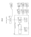
- FIG.3 is a block diagram of the control circuit 100 for the ink jet recording apparatus, including an interface 108 for receiving a recording signal, a MPU 101, a ROM 102 for storing data and a control program to be executed, and a DRAM 103 for storing the recording signal above and various data including recording data.
- a gate array 104 controls supplement of recording data for recording head 1, and also controls data transfer between the interface 108, MPU 101 and RAM 103.
- the apparatus further includes a carrier motor 110 for moving the carriage 2, a conveyance motor 109 for feeding the recording medium 3, a head driver 105 for driving the ink jet recording head 1, and motor drivers 106 and 107 for driving the conveyance motor 109 and carrier motor 110, respectively.
- control circuit 100 In operation of the control circuit 100, a recording signal applied to the interface 108 is converted to a recording data necessary for printing between gate array 104 and MPU 101. Then, when the motor drivers 106 and 107 are driven, the recording head 1 is driven in response to the recording data applied to head driver 105 to start printing. Control circuit 100 also controls the display device 111 for informing the status of the printer to the operator.
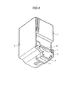
- FIG.4 shows an example of a summary view, which includes an ink tank 7 for storing ink, ink discharge outlets 8, an ink supplying member 9, a printed wiring board (PWB) 10 connected to heating element (not shown), a contact pads to be electrically connected to the apparatus when mounted on carriage 2, and a base plate 12 for assembling the above components.
- PWB printed wiring board
- FIG.5 shows an enlarged sectional view of the portion including the ink discharge outlet 8, in which a heating element 14 for discharging the bubbled ink is formed on a board 13 (hereinafter, referred to "heater board"), which is connected to PWB 10 and wires 15.
- a top board 21 is provided for forming therein a plurality of discharge outlets 8 and ink flow passages 16, and also for forming a communication chamber commonly communicating with the plurality of the passages 16.
- An ink supply passage 18 is formed to communicate the interior of the ink tank 7 enclosing the ink with the common liquid chamber 17 within the recording head 1.
- a filter 19 is also provided for removing dust or dirt in the ink, and is attached to the side end of ink tank 7 of the ink supply passage 18, wherein the ink passage ranging from ink tank 7 to the discharge outlet formed by the top board 21 is such that shown by the arrow as illustrated through the supply passage 18 and common chamber 17.
- FIG.6 is an enlarged perspective view of the heater board 13, in which the heating element 14 and wirings for connecting the element 14 are formed by repetition of film deposition by sputtering/vacuum evaporation and etching process. Further, there are illustrated a plurality of wire bondings 15 for connecting heating element 14 and PWB 10, and wires 20 for connecting to rank heater 22.
- Heating element 14 for heating the ink is formed by repetition of film forming and etching, wherein the dispersion of resistance values of heating element 14 is inevitably caused owing to variation of film thickness in the course of production, or variation of etching dimension in the etching process. As a result, even though the same voltage is applied, the quantity of generated heat for causing bubbling is varied and the discharged amount becomes indefinite.
- the rank heater 22, formed on the heater board 13, is affected by the variation of the result of film forming or etching to the same extent as affected by that in heating element 14. Although the rank heater 22 is different in configuration, this is also formed in the same step of forming heating element 14. By detecting the resistance value of the rank heater 22, it is possible to estimate the variation of the resistance value of the heating element 14. Based on the detected resistance value of rank heater 22, the time for applying voltage to the heating element 14 is controlled. Thus, the heat generation is maintained in substantially a constant value to stabilize the ink discharge amount.
- rank heater 22 Since the purpose of the rank heater 22 is not ejecting the ink by such heating, these can be designed in a dimension in its length or width according to the desired resistance value within the range of a limited space to establish a predetermined resistance value of rank heater 22.
- the dispersion range of such resistance value is set to be different from each other and not to be overlapped to any other range of the different types of the recording heads 1. In such a manner, the rank heater 22 are utilized to distinguish the type of recording heads.
- Table 1(a) shows the rank division for the recording apparatus A, and Table 1(b) for the apparatus B having discharge characteristics in discharge quantity, number of nozzles and drive frequencies different from the apparatus A, where the apparatus A and B utilize a different type of the recording head from each other.
- R 1 and R 2 are the lowest and highest limits of resistance, respectively, the range of which from R 1 to R 2 is divided in n parts.
- R 3 and R 4 are the lowest and highest limits of resistance, respectively, the range of which from R 1 to R 2 is divided in m parts.
- the resistance R of the rank heater 22 for the apparatus A is in the range from the value equal to or larger than the lowest value R 1 , and lower than or equal to the greatest value R 2 .
- the resistance R of the rank heater 22 for the apparatus B is in the range from the value equal to or larger than the lowest value R 3 , and lower than or equal to the greatest value R 4 .
- the relation thereof is such that either R 2 is lower than R 3 , or R 4 is lower than R 1 , hence the resistance ranges of apparatus A and B is designed not to be overlapped with each other.
- a recording head la for apparatus A is mounted on the apparatus A in Step S1, and, in the subsequent Step S2, the resistance value R of the rank heater is read.
- the read value R is determined to be included within the range from R 1 to R 2
- the treatment is advanced to Step S4 and the rank number is selected on the basis of the rank table in Table 1(a).
- the pulse width and other factors are decided, and, based on the recording data entered in Step S5, the printing operation is performed in Step S6.
- the rank number is selected from those in Table(b), and printing is performed.
- Step S17 the treatment is moved to Step S17, where the recording apparatus is disabled or such error state is displayed on the display device 111 in FIG.3 to suspend the printing operation.
- the rank heater 22 having a simple and important structure providing an adequate bubbling condition for each head, may be added with an identification ability for different types of heads. As a result, a minimum construction for the recording head 1 is achieved without increasing the number of contact pads on the heater board 13 of the head 1 and without modifying the PWB 10 shown in FIGS. 4 and 5. Also in the printing apparatus, since the existing function or error display is performed with merely a minimum addition, a recording apparatus with a low cost and high reliability is provided.
- a plurality of recording heads 1 are replaced on one carriage 2, where it is necessary that the recording heads are distinguished from each other to select the driving condition.
- the present invention is effective for providing such detecting means with a low cost in the recording heads and recording apparatus, and also effective for correctly identifying the recording head to achieve the printing with high reliability.
- a plurality of recording heads are interchangeably mounted, such as, one head for black printing only for performing high speed printing using the entire heads; another for three colors including yellow, magenta and cyan; and still another for four colors including said three colors and black.
- a printing apparatus for using interchangeable heads by providing a rank heater for each of the above-mentioned recording heads in the range of not overlapped on each other and identifying the resistance value thereof at the side of the recording apparatus, the selection of the driving condition for each head is enabled.
- the ink jet printing is applied to a large sized printer such as a plotter for printing on a medium over the A2 size for the purpose of design drawing, a high speed operation and an increased capacity for storing the ink are required.
- a large sized printer such as a plotter for printing on a medium over the A2 size for the purpose of design drawing
- four separate heads each as an independent head for each color of black, yellow, magenta and cyan are preferably mounted on the printer.
Landscapes
- Particle Formation And Scattering Control In Inkjet Printers (AREA)
- Ink Jet (AREA)
Applications Claiming Priority (3)
| Application Number | Priority Date | Filing Date | Title |
|---|---|---|---|
| JP33206795 | 1995-12-20 | ||
| JP7332067A JPH09169114A (ja) | 1995-12-20 | 1995-12-20 | インクジェット記録装置 |
| JP332067/95 | 1995-12-20 |
Publications (2)
| Publication Number | Publication Date |
|---|---|
| EP0780236A1 true EP0780236A1 (fr) | 1997-06-25 |
| EP0780236B1 EP0780236B1 (fr) | 2003-05-02 |
Family
ID=18250782
Family Applications (1)
| Application Number | Title | Priority Date | Filing Date |
|---|---|---|---|
| EP96309233A Expired - Lifetime EP0780236B1 (fr) | 1995-12-20 | 1996-12-18 | Dispositif d'enregistrement avec une tête d'enregistrement identifiable et tête d'enregistrement ayant une fonction identifiable |
Country Status (4)
| Country | Link |
|---|---|
| US (1) | US6113213A (fr) |
| EP (1) | EP0780236B1 (fr) |
| JP (1) | JPH09169114A (fr) |
| DE (1) | DE69627795T2 (fr) |
Cited By (6)
| Publication number | Priority date | Publication date | Assignee | Title |
|---|---|---|---|---|
| EP1147897A3 (fr) * | 2000-04-05 | 2002-05-08 | Hewlett-Packard Company | Impression à jet d'encre |
| EP1661711A1 (fr) * | 2004-11-08 | 2006-05-31 | Samsung Electronics Co., Ltd. | Appareil de formation des images |
| EP2133209A3 (fr) * | 2008-06-12 | 2010-02-24 | Toshiba TEC Kabushiki Kaisha | Appareil d'impression |
| WO2013001370A1 (fr) * | 2011-06-29 | 2013-01-03 | Markem-Imaje | Interface utilisateur dynamique |
| WO2016085471A1 (fr) * | 2014-11-25 | 2016-06-02 | Hewlett-Packard Development Company, L.P. | Composant de propulsion de liquide |
| US10154163B2 (en) | 2011-06-29 | 2018-12-11 | Markem-Imaje Holding | Dynamic user interface |
Families Citing this family (5)
| Publication number | Priority date | Publication date | Assignee | Title |
|---|---|---|---|---|
| JP3880411B2 (ja) * | 2001-01-31 | 2007-02-14 | キヤノン株式会社 | 記録装置 |
| US7344212B2 (en) * | 2004-08-16 | 2008-03-18 | Lexmark International, Inc. | Imaging apparatus having a programmable throughput rate |
| EP1634722B8 (fr) * | 2004-09-09 | 2009-10-07 | Alcan Technology & Management Ltd. | Article avec une impression contre la falsification |
| JP2009297997A (ja) * | 2008-06-12 | 2009-12-24 | Toshiba Tec Corp | 印刷装置及び印刷装置の制御方法 |
| US10369804B2 (en) * | 2017-11-10 | 2019-08-06 | Datamax-O'neil Corporation | Secure thermal print head |
Citations (7)
| Publication number | Priority date | Publication date | Assignee | Title |
|---|---|---|---|---|
| EP0374762A2 (fr) * | 1988-12-16 | 1990-06-27 | Canon Kabushiki Kaisha | Appareil d'enregistrement avec tête d'enregistrement amovible |
| JPH02215551A (ja) * | 1989-02-17 | 1990-08-28 | Hitachi Ltd | 印字装置のヘッド制御方式 |
| US5033887A (en) * | 1988-07-25 | 1991-07-23 | Nixdorf Computer Ag | Process for the production of information relative to the type of a printing head |
| US5049898A (en) | 1989-03-20 | 1991-09-17 | Hewlett-Packard Company | Printhead having memory element |
| EP0571093A2 (fr) * | 1992-05-20 | 1993-11-24 | Hewlett-Packard Company | Tête d'impression à circuit intégré pour imprimante à jet d'encre comprenant un circuit intégré d'identification |
| US5289210A (en) * | 1991-01-14 | 1994-02-22 | Canon Kabushiki Kaisha | Image recording apparatus |
| EP0626266A2 (fr) * | 1993-05-27 | 1994-11-30 | Canon Kabushiki Kaisha | Appareil d'enregistrement commandé par les caractéristiques de la tête et méthode d'enregistrement |
-
1995
- 1995-12-20 JP JP7332067A patent/JPH09169114A/ja active Pending
-
1996
- 1996-12-17 US US08/767,786 patent/US6113213A/en not_active Expired - Lifetime
- 1996-12-18 DE DE69627795T patent/DE69627795T2/de not_active Expired - Lifetime
- 1996-12-18 EP EP96309233A patent/EP0780236B1/fr not_active Expired - Lifetime
Patent Citations (7)
| Publication number | Priority date | Publication date | Assignee | Title |
|---|---|---|---|---|
| US5033887A (en) * | 1988-07-25 | 1991-07-23 | Nixdorf Computer Ag | Process for the production of information relative to the type of a printing head |
| EP0374762A2 (fr) * | 1988-12-16 | 1990-06-27 | Canon Kabushiki Kaisha | Appareil d'enregistrement avec tête d'enregistrement amovible |
| JPH02215551A (ja) * | 1989-02-17 | 1990-08-28 | Hitachi Ltd | 印字装置のヘッド制御方式 |
| US5049898A (en) | 1989-03-20 | 1991-09-17 | Hewlett-Packard Company | Printhead having memory element |
| US5289210A (en) * | 1991-01-14 | 1994-02-22 | Canon Kabushiki Kaisha | Image recording apparatus |
| EP0571093A2 (fr) * | 1992-05-20 | 1993-11-24 | Hewlett-Packard Company | Tête d'impression à circuit intégré pour imprimante à jet d'encre comprenant un circuit intégré d'identification |
| EP0626266A2 (fr) * | 1993-05-27 | 1994-11-30 | Canon Kabushiki Kaisha | Appareil d'enregistrement commandé par les caractéristiques de la tête et méthode d'enregistrement |
Non-Patent Citations (1)
| Title |
|---|
| PATENT ABSTRACTS OF JAPAN vol. 14, no. 517 (M - 1047) 13 November 1990 (1990-11-13) * |
Cited By (12)
| Publication number | Priority date | Publication date | Assignee | Title |
|---|---|---|---|---|
| EP1147897A3 (fr) * | 2000-04-05 | 2002-05-08 | Hewlett-Packard Company | Impression à jet d'encre |
| US6825951B1 (en) | 2000-04-05 | 2004-11-30 | Hewlett-Packard Development Company, L.P. | Inkjet printing and method |
| EP1661711A1 (fr) * | 2004-11-08 | 2006-05-31 | Samsung Electronics Co., Ltd. | Appareil de formation des images |
| US7649542B2 (en) | 2004-11-08 | 2010-01-19 | Samsung Electronics Co., Ltd. | Apparatus and method for forming image by detecting thermal print head type |
| EP2133209A3 (fr) * | 2008-06-12 | 2010-02-24 | Toshiba TEC Kabushiki Kaisha | Appareil d'impression |
| US8049770B2 (en) | 2008-06-12 | 2011-11-01 | Toshiba Tec Kabushiki Kaisha | Printing apparatus |
| WO2013001370A1 (fr) * | 2011-06-29 | 2013-01-03 | Markem-Imaje | Interface utilisateur dynamique |
| US10154163B2 (en) | 2011-06-29 | 2018-12-11 | Markem-Imaje Holding | Dynamic user interface |
| WO2016085471A1 (fr) * | 2014-11-25 | 2016-06-02 | Hewlett-Packard Development Company, L.P. | Composant de propulsion de liquide |
| TWI593564B (zh) * | 2014-11-25 | 2017-08-01 | 惠普發展公司有限責任合夥企業 | 液體推進組件 |
| CN107073958A (zh) * | 2014-11-25 | 2017-08-18 | 惠普发展公司,有限责任合伙企业 | 液体推进组件 |
| CN107073958B (zh) * | 2014-11-25 | 2018-11-13 | 惠普发展公司,有限责任合伙企业 | 液体推进组件 |
Also Published As
| Publication number | Publication date |
|---|---|
| US6113213A (en) | 2000-09-05 |
| DE69627795T2 (de) | 2004-02-19 |
| DE69627795D1 (de) | 2003-06-05 |
| EP0780236B1 (fr) | 2003-05-02 |
| JPH09169114A (ja) | 1997-06-30 |
Similar Documents
| Publication | Publication Date | Title |
|---|---|---|
| KR100835030B1 (ko) | 잉크 제트 기록 헤드 및 이를 사용하는 잉크 제트 기록장치 | |
| EP0992348B1 (fr) | Cartouche d'impression modulaire pour usage dans des systèmes d'impression à jet d'encre | |
| EP1602485B1 (fr) | Tête d'éjection de liquide et dispositif d'éjection de liquide en utilisable | |
| US8113611B2 (en) | Micro-fluid ejection apparatus signal communication devices and methods | |
| EP0916496B1 (fr) | Appareil d'impression et procédé de commande d'impression | |
| EP1898340B1 (fr) | Tête d'enregistrement à jet d'encre | |
| EP0780236B1 (fr) | Dispositif d'enregistrement avec une tête d'enregistrement identifiable et tête d'enregistrement ayant une fonction identifiable | |
| CN107073939B (zh) | 打印头和喷墨打印机 | |
| JP4143319B2 (ja) | 記録装置及びインク消費量管理方法 | |
| JPH06262771A (ja) | インクジェット記録装置 | |
| US5992961A (en) | Ink jet recording apparatus, method for determining reduced ink remains, and information processing apparatus | |
| JP3531366B2 (ja) | インクジェット記録装置 | |
| CN114083900B (zh) | 打印元件基板、打印头和打印装置 | |
| JPH1086349A (ja) | 印字装置に搭載された印字ヘッドの特性ランク識別方法及びそれを用いた印字装置 | |
| US7918527B2 (en) | Method for use in achieving velocity optimization for a printhead | |
| JP3156423B2 (ja) | インクジェット記録装置 | |
| JPH1071708A (ja) | インクジェット記録装置 | |
| JP2005231250A (ja) | 印刷装置、及び印刷システム | |
| JP2002200819A (ja) | 記録装置 | |
| HK1144156A (en) | Ink jet printing head and ink jet printing apparatus using the same | |
| HK1095792B (en) | Ink jet printing head and ink jet printing apparatus using the same | |
| HK1077265B (en) | Liquid ejecting head and liquid ejecting apparatus usable therewith | |
| JPH08112960A (ja) | データ出力装置 |
Legal Events
| Date | Code | Title | Description |
|---|---|---|---|
| PUAI | Public reference made under article 153(3) epc to a published international application that has entered the european phase |
Free format text: ORIGINAL CODE: 0009012 |
|
| AK | Designated contracting states |
Kind code of ref document: A1 Designated state(s): DE FR GB IT |
|
| 17P | Request for examination filed |
Effective date: 19971105 |
|
| 17Q | First examination report despatched |
Effective date: 19990630 |
|
| GRAG | Despatch of communication of intention to grant |
Free format text: ORIGINAL CODE: EPIDOS AGRA |
|
| GRAG | Despatch of communication of intention to grant |
Free format text: ORIGINAL CODE: EPIDOS AGRA |
|
| GRAH | Despatch of communication of intention to grant a patent |
Free format text: ORIGINAL CODE: EPIDOS IGRA |
|
| GRAH | Despatch of communication of intention to grant a patent |
Free format text: ORIGINAL CODE: EPIDOS IGRA |
|
| GRAA | (expected) grant |
Free format text: ORIGINAL CODE: 0009210 |
|
| AK | Designated contracting states |
Designated state(s): DE FR GB IT |
|
| REG | Reference to a national code |
Ref country code: GB Ref legal event code: FG4D |
|
| REF | Corresponds to: |
Ref document number: 69627795 Country of ref document: DE Date of ref document: 20030605 Kind code of ref document: P |
|
| ET | Fr: translation filed | ||
| PLBE | No opposition filed within time limit |
Free format text: ORIGINAL CODE: 0009261 |
|
| STAA | Information on the status of an ep patent application or granted ep patent |
Free format text: STATUS: NO OPPOSITION FILED WITHIN TIME LIMIT |
|
| 26N | No opposition filed |
Effective date: 20040203 |
|
| PGFP | Annual fee paid to national office [announced via postgrant information from national office to epo] |
Ref country code: IT Payment date: 20081217 Year of fee payment: 13 |
|
| PGFP | Annual fee paid to national office [announced via postgrant information from national office to epo] |
Ref country code: FR Payment date: 20081222 Year of fee payment: 13 |
|
| REG | Reference to a national code |
Ref country code: FR Ref legal event code: ST Effective date: 20100831 |
|
| PG25 | Lapsed in a contracting state [announced via postgrant information from national office to epo] |
Ref country code: FR Free format text: LAPSE BECAUSE OF NON-PAYMENT OF DUE FEES Effective date: 20091231 |
|
| PG25 | Lapsed in a contracting state [announced via postgrant information from national office to epo] |
Ref country code: IT Free format text: LAPSE BECAUSE OF NON-PAYMENT OF DUE FEES Effective date: 20091218 |
|
| PGFP | Annual fee paid to national office [announced via postgrant information from national office to epo] |
Ref country code: DE Payment date: 20141231 Year of fee payment: 19 Ref country code: GB Payment date: 20141222 Year of fee payment: 19 |
|
| REG | Reference to a national code |
Ref country code: DE Ref legal event code: R119 Ref document number: 69627795 Country of ref document: DE |
|
| GBPC | Gb: european patent ceased through non-payment of renewal fee |
Effective date: 20151218 |
|
| PG25 | Lapsed in a contracting state [announced via postgrant information from national office to epo] |
Ref country code: GB Free format text: LAPSE BECAUSE OF NON-PAYMENT OF DUE FEES Effective date: 20151218 Ref country code: DE Free format text: LAPSE BECAUSE OF NON-PAYMENT OF DUE FEES Effective date: 20160701 |