EP0571177A1 - Cartouche de développateur et appareil de formation d'images utilisant cette cartouche - Google Patents
Cartouche de développateur et appareil de formation d'images utilisant cette cartouche Download PDFInfo
- Publication number
- EP0571177A1 EP0571177A1 EP93303832A EP93303832A EP0571177A1 EP 0571177 A1 EP0571177 A1 EP 0571177A1 EP 93303832 A EP93303832 A EP 93303832A EP 93303832 A EP93303832 A EP 93303832A EP 0571177 A1 EP0571177 A1 EP 0571177A1
- Authority
- EP
- European Patent Office
- Prior art keywords
- cartridge
- storage room
- developer
- toner
- inner drum
- Prior art date
- Legal status (The legal status is an assumption and is not a legal conclusion. Google has not performed a legal analysis and makes no representation as to the accuracy of the status listed.)
- Granted
Links
Images


Classifications
-
- G—PHYSICS
- G03—PHOTOGRAPHY; CINEMATOGRAPHY; ANALOGOUS TECHNIQUES USING WAVES OTHER THAN OPTICAL WAVES; ELECTROGRAPHY; HOLOGRAPHY
- G03G—ELECTROGRAPHY; ELECTROPHOTOGRAPHY; MAGNETOGRAPHY
- G03G15/00—Apparatus for electrographic processes using a charge pattern
- G03G15/06—Apparatus for electrographic processes using a charge pattern for developing
- G03G15/08—Apparatus for electrographic processes using a charge pattern for developing using a solid developer, e.g. powder developer
- G03G15/0822—Arrangements for preparing, mixing, supplying or dispensing developer
- G03G15/0844—Arrangements for purging used developer from the developing unit
-
- G—PHYSICS
- G03—PHOTOGRAPHY; CINEMATOGRAPHY; ANALOGOUS TECHNIQUES USING WAVES OTHER THAN OPTICAL WAVES; ELECTROGRAPHY; HOLOGRAPHY
- G03G—ELECTROGRAPHY; ELECTROPHOTOGRAPHY; MAGNETOGRAPHY
- G03G15/00—Apparatus for electrographic processes using a charge pattern
- G03G15/06—Apparatus for electrographic processes using a charge pattern for developing
- G03G15/08—Apparatus for electrographic processes using a charge pattern for developing using a solid developer, e.g. powder developer
- G03G15/0822—Arrangements for preparing, mixing, supplying or dispensing developer
- G03G15/0865—Arrangements for supplying new developer
- G03G15/0867—Arrangements for supplying new developer cylindrical developer cartridges, e.g. toner bottles for the developer replenishing opening
- G03G15/0868—Toner cartridges fulfilling a continuous function within the electrographic apparatus during the use of the supplied developer material, e.g. toner discharge on demand, storing residual toner, acting as an active closure for the developer replenishing opening
-
- G—PHYSICS
- G03—PHOTOGRAPHY; CINEMATOGRAPHY; ANALOGOUS TECHNIQUES USING WAVES OTHER THAN OPTICAL WAVES; ELECTROGRAPHY; HOLOGRAPHY
- G03G—ELECTROGRAPHY; ELECTROPHOTOGRAPHY; MAGNETOGRAPHY
- G03G15/00—Apparatus for electrographic processes using a charge pattern
- G03G15/06—Apparatus for electrographic processes using a charge pattern for developing
- G03G15/08—Apparatus for electrographic processes using a charge pattern for developing using a solid developer, e.g. powder developer
- G03G15/0822—Arrangements for preparing, mixing, supplying or dispensing developer
- G03G15/0877—Arrangements for metering and dispensing developer from a developer cartridge into the development unit
- G03G15/0881—Sealing of developer cartridges
- G03G15/0886—Sealing of developer cartridges by mechanical means, e.g. shutter, plug
-
- G—PHYSICS
- G03—PHOTOGRAPHY; CINEMATOGRAPHY; ANALOGOUS TECHNIQUES USING WAVES OTHER THAN OPTICAL WAVES; ELECTROGRAPHY; HOLOGRAPHY
- G03G—ELECTROGRAPHY; ELECTROPHOTOGRAPHY; MAGNETOGRAPHY
- G03G2215/00—Apparatus for electrophotographic processes
- G03G2215/06—Developing structures, details
- G03G2215/066—Toner cartridge or other attachable and detachable container for supplying developer material to replace the used material
- G03G2215/0663—Toner cartridge or other attachable and detachable container for supplying developer material to replace the used material having a longitudinal rotational axis, around which at least one part is rotated when mounting or using the cartridge
- G03G2215/0665—Generally horizontally mounting of said toner cartridge parallel to its longitudinal rotational axis
- G03G2215/067—Toner discharging opening covered by arcuate shutter
-
- G—PHYSICS
- G03—PHOTOGRAPHY; CINEMATOGRAPHY; ANALOGOUS TECHNIQUES USING WAVES OTHER THAN OPTICAL WAVES; ELECTROGRAPHY; HOLOGRAPHY
- G03G—ELECTROGRAPHY; ELECTROPHOTOGRAPHY; MAGNETOGRAPHY
- G03G2215/00—Apparatus for electrophotographic processes
- G03G2215/06—Developing structures, details
- G03G2215/066—Toner cartridge or other attachable and detachable container for supplying developer material to replace the used material
- G03G2215/0663—Toner cartridge or other attachable and detachable container for supplying developer material to replace the used material having a longitudinal rotational axis, around which at least one part is rotated when mounting or using the cartridge
- G03G2215/0675—Generally cylindrical container shape having two ends
-
- G—PHYSICS
- G03—PHOTOGRAPHY; CINEMATOGRAPHY; ANALOGOUS TECHNIQUES USING WAVES OTHER THAN OPTICAL WAVES; ELECTROGRAPHY; HOLOGRAPHY
- G03G—ELECTROGRAPHY; ELECTROPHOTOGRAPHY; MAGNETOGRAPHY
- G03G2215/00—Apparatus for electrophotographic processes
- G03G2215/06—Developing structures, details
- G03G2215/066—Toner cartridge or other attachable and detachable container for supplying developer material to replace the used material
- G03G2215/0685—Toner cartridge or other attachable and detachable container for supplying developer material to replace the used material fulfilling a continuous function within the electrographic apparatus during the use of the supplied developer material, e.g. toner discharge on demand, storing residual toner, not acting as a passive closure for the developer replenishing opening
Definitions
- the present invention relates to a developer cartridge for exchanging developers in a developing apparatus which develops an electrostatic latent image, and an image forming apparatus using this developer cartridge.
- an electrostatic latent image is formed on a latent image carrier like a photosensitive drum.
- a developing apparatus is used to develop an electrostatic latent image with a developer.
- a typical developer used in the developing apparatus is composed of two components, toner and carrier. As the toner in this developer is consumed in a developing process, the toner should be supplemented. Further, the developer in the developing apparatus is deteriorated with the passage of time so that the quality of an image becomes lower. It is therefore necessary to exchange the old developer with a new one. Recently, this exchange is often conducted by the user of the image forming apparatus. In this respect, there is a demand for an image forming apparatus designed to facilitate the developer exchange without making the operator's hands dirty.
- the developer exchange is conducted as follows. A developer cartridge containing an unused developer and an empty collecting cartridge for collecting the developer in the developing apparatus are placed in the developing apparatus. Then, after the developer in the developing apparatus is collected in the collecting cartridge, the unused developer is supplied into the developing apparatus from the developer cartridge. This method involves two cartridges, thus complicating the exchange.
- U.S.P. Serial No. 5,109,254 and Japanese Unexamined Patent Publication No. 118675/1992 proposed a developer cartridge having those two cartridges designed as a single cartridge to ensure automatic exchange of developers.
- a developer exchanging section is provided on a side of the developing apparatus.
- the developer cartridge comprises a cylindrical portion, a developer storage room which is located above the cylindrical portion and where an used developer is retained, and a collecting room located under the cylindrical portion.
- This developer cartridge is placed in the developer exchanging section of the developing apparatus. More specifically, the cylindrical portion of the developer cartridge is fitted in the developer exchanging section of the developing apparatus.
- the shutter of the collecting room of the developer cartridge When the shutter of the collecting room of the developer cartridge is open, the used developer in the developing apparatus falls into the collecting room from the developer exchanging section. Then, the shutter of the collecting room is closed and the shutter of the developer storage room is open. As a result, the unused developer in the developer storage room falls into the developer exchanging section to be supplied into the developing apparatus. The developer in the developing apparatus is exchanged with an used developer in this manner.
- This method is effective when there is a small amount of the developer to be exchanged.
- it is necessary to make the developer storage room and collecting room of the developer cartridge longer.
- the developer cartridge inevitably becomes larger in length. This makes the handling of the developer cartridge troublesome, and requires extra space for storage of such developer cartridges. It is also necessary to provide extra space for placing the developer cartridge in the developing apparatus.
- the developer exchanging section of the developing apparatus is used only for developer exchange, it is cost effective to make this section smaller. But, it is troublesome to conduct the developer exchange in the small exchanging space.
- a cartridge for exchanging image-forming materials in an image-forming process including a first storage room for storing unused material, a second storage room located under the first storage room for storing used material: first and second openings respectively formed in the first and second storage rooms; first and second shutter means respectively provided in association with the first and second openings; characterised in that an urging means is disposed in the first storage room for urging the unused material out of the first storage room.
- the unused material, for example developer, in the first developer storage room can be supplied into the developing apparatus using the urging member, for example a paddling member, the second storage room can be provided directly under the first storage room.
- This design allows the cartridge to be smaller. Accordingly, it is easier to handle the cartridge and it is possible to reduce the space necessary for material exchange, for example developer.
- the cartridge has a conveying screw provided below the opening of the protruding portion of the second storage room to convey the material into the second storage room.
- This design is arranged such that the used material may be effectively stored in the second storage room even when the cartridge is made smaller.
- the second storage room of the cartridge has a bottom inclined to the face of the protruding portion where the opening and shutter means are provided.
- This design permits the used material coming through the opening to proceed deeper into the second storage room owing to its dead weight, thus preventing the material from clogging at the opening area.
- an image forming apparatus including an endless latent carrier, means for forming an electrostatic latent image on the endless latent carrier, a developing apparatus for developing the electrostatic latent image on the endless latent carrier, characterised in that there is provided a means for receiving a cartridge and a drive means for driving the shutter means of the cartridge when attached and/or for driving the urging means of the cartridge for exchanging used material with unused material.
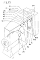
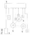
- Fig. 1 illustrates the outline of a printing machine according to one embodiment of the present invention
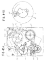
- Fig. 2 illustrates the structure of the printing machine in Fig. 1
- Fig. 3 shows the arrangement of the essential portions in the structure of Fig. 2.
- an image forming apparatus is constituted of a printing machine.
- This printing machine includes three paper cassettes 10 for retaining printing sheets, left and right doors 11 and 12 of a print mechanism shown in Fig. 2, a stacker 13 provided at an upper portion for retaining printed sheets, and an operation panel 14 for operating the printing machine.
- a printing machine includes three paper cassettes 10 for retaining printing sheets, left and right doors 11 and 12 of a print mechanism shown in Fig. 2, a stacker 13 provided at an upper portion for retaining printed sheets, and an operation panel 14 for operating the printing machine.
- the print mechanism has a rotatable photosensitive drum 30, a precharger 31 for electrifying the photosensitive drum 30, a laser optical unit 32 which writes a light image on the photosensitive drum 30 to form a latent image thereon, a developing apparatus 4 for developing the latent image on the photosensitive drum 30 with a toner, a transfer/separating unit 33 for transferring a toner image of the photosensitive drum 30 onto a sheet to be fed and separating this sheet, and a cleaner 34 for cleaning the photosensitive drum 30 after the image transfer.
- a developer cartridge 5 is attached to this developing apparatus 4 for collecting the developer, supplying the developer, supplementing a toner and collecting a waste toner.
- this printing machine After the photosensitive drum 30 is electrified by the precharger 31, a light image is written on the drum 30 by the optical system unit 32 to form a latent image thereon. Then, the photosensitive drum 30 is developed to have a toner image by the developing apparatus 4. In the meantime, the printing sheet is picked up from the associated sheet cassette 10 by the pick rollers 20, and is fed to the hold roller 22 by the feed rollers 21. This sheet is held by the resist roller 22 to be in synchronism with the toner image on the photosensitive drum 30.
- the transfer/separating unit 33 transfers the toner image of the photosensitive drum 30 onto the sheet fed by the hold roller 22, and then separates the sheet from the photosensitive drum 30.
- the sheet is fed toward the switchback rollers 25. Further, the sheet is fed toward the stacker 13 by the switchback rollers 25.
- the switchback rollers 25 stop feeding the sheet.
- the rear end of the sheet is directed toward the back-printing feeding passage 26 by the counterclockwise rotation of the blade wheel 24.
- the switchback rollers rotate in the reverse direction to feed the sheet to the back-printing feeding passage 26.
- the sheet is further fed to the resist roller 22 by the feed rollers of the back-printing feeding passage 26.
- the transfer/separating unit 33 transfers the toner image of the photosensitive drum 30 on the back of the sheet and separates it from the photosensitive drum 30 as per the front printing of the sheet.
- the sheet is fed toward the switchback rollers 25. Further, the sheet is fed toward the stacker 13 by the switchback rollers 25, and is discharged on the stacker 13 by discharge rollers 28. Double-side printing is performed on the sheet in this manner. For single-side printing, the sheet is discharged on the stacker 13 after printing is done only on the top surface of the sheet.
- the sheet cassettes 10 are mounted into the machine from the front and the sheet is discharged onto the overlying stacker 13 as shown in Fig. 1.
- This design requires no space on either side of the machine, thus making it possible to reduce the space. Further, as the discharging passage is used in the switchback path, the double-side printing machine can be made compact.
- the developing apparatus 4 has a developing roller 40, which rotates counterclockwise to supply the developer to the photosensitive drum 30, a pair of stirring screws 41 for stirring the developer, which is comprised of toner and carrier, a collecting blade 48 for scraping the developer off the developing roller 40 and returning the scraped developer back to the stirring screws 41, and a toner supply roller 43 for supplying a toner into the developing apparatus 4. Further, an injection port 44 for receiving the developer and toner from the cartridge 5. This injection port 44 faces outlet ports 72 and 73 of the cartridge 5, which will be described later.
- a discharge port 45 for discharging the developer and a discharge shutter 46 which covers the discharge port 45.
- the discharge port 45 and discharge shutter 46 face a collecting section 77 of the cartridge 5.
- This cartridge 5 is positioned opposite the photosensitive drum 30 of the developing apparatus 4. Therefore, it is possible to dispose only the developing apparatus 4 in the space around the photosensitive drum 30 and arrange the cartridge 5 in the free space therearound. It is thus unnecessary to provide space for the cartridge 5 in the narrow space around the photosensitive drum 30, contributing to making the image forming apparatus compact. As the cartridge 5 is placed in the free space, a relatively large cartridge 5 can be installed. Further, the cartridge 5 is disposed by the developing apparatus 4, the cartridge 5 can be made smaller.
- Fig. 4 is a top view of the developing apparatus
- Fig. 5 is a cross section taken along the line A-A in Fig. 4
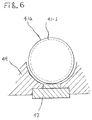
- Fig. 6 is an explanatory diagram of a toner density sensor
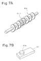
- Fig. 7A is a perspective view of the stirring screw
- Fig. 7B is a perspective view of the toner density sensor.
- a pair of stirring screws 41a and 41b are each constituted of a spiral screw.
- the stirring screws 41a and 41b rotate in the opposite directions.
- a partition 41c is provided between the stirring screws 41a and 41b.
- the stirring screw 41b stirs the developer while conveying it rightward in the diagram.
- the developer conveyed by the stirring screw 41b gets over the partition 41c onto the stirring screw 41a.
- the stirring screw 41a stirs the developer while conveying the developer leftward in the diagram to supply it to the developing roller 40.
- This design permits the developer to be sufficiently stirred and minimizes the developer that will not be stirred. This design is indicated by PCT application No. JP92/01452 dated November 9, 1992.
- the toner density sensor 47 is attached so that its upper end will not be positioned below the U-shaped bottom of the container 49.
- the toner density sensor 47 is attached slightly below the bottom of the container 49 in order to avoid a contact with the stirring screw 41a. In this case, however, the developer stays in the clearance between the bottom of the container 49 and the sensor 47, and the toner density cannot be detected accurately.
- the toner density sensor 47 is attached so that its upper end is not positioned below the U-shaped bottom of the container 49.
- the toner density sensor 47 in this arrangement may contact the stirring screw 41a. To avoid this problem, that outer surface of the stirring screw 41a which faces the toner density sensor 47 is cut so that the screw 41a will not hit against the top end of the toner density sensor 47.
- Fig. 8 is a front view of the drum unit shown
- Fig. 9 is a side view of the drum unit
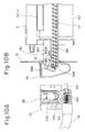
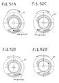
- Fig. 10A is a front view of a waste toner collecting mechanism shown
- Fig. 10B is a side view of the toner collecting mechanism
- Fig. 11 is a diagram for explaining the operation of the toner collecting mechanism
- Fig. 12 is an explanatory diagram of a modification of the toner collecting mechanism
- Fig. 13 is an explanatory diagram of another modification of the toner collecting mechanism.
- the drum unit 3 has the photosensitive drum 30, the precharger 31 and the cleaner 34 assembled as a single unit.
- the cleaner 34 has a scraping blade 34-1 for scraping the residue toner off the photosensitive drum 30, a cleaning roller 34-2 that rotates to remove the residue toner on the photosensitive drum 30, and a waste toner discharging screw 37 for discharging the toner, removed by the blade 34-1 and roller 34-2 and accumulated in the cleaner 34, outside.
- This cap 382 is provided to cap the distal end of the toner discharging pipe 381 to prevent the toner from leaking from the cleaner 34 when the drum unit 3, detachably attached to the image forming apparatus, is detached therefrom for replacement.
- the toner carrying operation will now be described.
- the drum unit 3 in Fig. 9 is inserted into the apparatus in the arrow direction in the diagram for its replacement.
- the toner discharging mechanism 38 of the cleaner 34 enters the hole of the frame 15. Accordingly, an engage lever 382a of the cap 382 of the toner discharging mechanism 38 abuts on the engaging projection 16 of the frame 15, thereby rotating the cap 382 around the pin 383, as shown in Figs. 10A and 10B.
- the distal end of the discharging pipe 381 becomes free so that the toner can be discharged from an opened portion 384 by the discharging screw 37. This is illustrated in Fig. 11.
- the lower portion of the distal end of the discharging pipe 381 becomes free by the cap 382 to discharge the waste toner from the lower portion 384 of the discharging pipe 381 as shown in Fig. 11.
- the discharged toner falls in the waste toner carrying block 39 and is carried inside the waste toner carrying pipe 35 by the carrying screw 350 to a waste toner discharging section 36 shown in Fig. 3.
- Fig. 12 illustrates a modification of the toner discharging mechanism 38.
- an obliquely cut portion 381b is provided at the distal end of the discharging pipe 381 and the cap 382 is provided with a protruding portion 382a in this modification.
- the cap 382 when the cap 382 is open, only the lower portipn of the end face of the discharging pipe 381 is opened.
- the toner absorbs water and the fluidity gets lower, the toner will not fall from the aforementioned opened portion 384 and will be carried to the cap 382.
- the toner is kept pressed by the cap 382 by the discharging screw 37, the toner sticks firmly on the cap 382.
- the obliquely cut portion 381b is provided on the discharging pipe 381 to make the opened portion wider. Accordingly, the toner discharging port becomes wider so that the toner can surely be discharged. Even when the toner absorbs water to reduce the fluidity, it is possible to prevent the toner from firmly sticking on the cap 382.
- Fig. 13 illustrates another modification of the toner discharging mechanism 38.
- This modification has an auxiliary pipe 381c provided at the front edge portion of the discharging pipe 381 as shown in Fig. 13.
- This auxiliary pipe 381c is engaged slidable in the axial direction of the discharging pipe 381.
- the auxiliary pipe 381c is connected to a spring 381d provided at the protruding block 380a of the drum unit 3 and is urged toward the cap 382. Therefore, the auxiliary pipe 381c abuts against the cap 382 to accomplish the capping of the discharging pipe 381, as shown in Fig. 13.
- the cap 382 When the drum unit 3 is installed, the cap 382 is rotated by the engaging projection 16, and the auxiliary pipe 381c abuts against another engaging projection 17 provided on the frame 15 to compress the spring 381d and move away from the front end portion of the discharging pipe 381.
- the opened portion of the discharging pipe 381 becomes wider accordingly. Therefore, the toner discharging port becomes wide to allow the toner to be surely discharged as in the modification of Fig. 12. Even when the toner absorbs water to reduce the fluidity, therefore, it is possible to prevent the toner from firmly sticking on the cap 382.
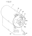
- a top handle 51 is provided at the top of the cartridge 5 for easier holding by a human hand, and a side handle 51 is provided on the right-hand side of the cartridge 5 which will be used to manually detach the cartridge 5.
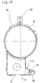
- the cartridge 5 comprises an inner drum 6 and an outer case 7 having an inner drum retaining section 70 to retain the inner drum 6 and a waste developer storage room 71.
- This waste developer storage room 71 serves to store the used developer of the developing apparatus 4.
- the outer case 7 is provided with developer injection ports 72 and toner injection ports 73 at the lower portion of the inner drum 6 retaining section 70, and is provided with a waste toner collecting port 75 at the upper portion of the drum retaining section 70.
- the waste developer storage room 71 of the outer case 7 is provided with a collecting shutter 74 which covers the collecting port 77.
- the interior of the inner drum 6 is divided into right and left portions by a partition 62.
- One is a developer storage room 60 for storing an unused developer, and the other is a toner storage room 61 for storing a supplemental toner.
- the developer storage room 60 is provided with developer supply ports 63 for discharging the unused developer and a paddle 64 for discharging the developer.
- the toner storage room 61 is provided with toner supply ports 65 for discharging a supplemental toner and a paddle 66 for discharging the toner.
- a paddle shaft 64a Disposed in the centre of the inner drum 6 is a paddle shaft 64a for driving both paddles 64 and 66.
- the paddles are generally in the form of bars or baffles extending substantially axially over the length of their respective chambers near the drum wall, so as to agitate the material in the respective chambers 60,61.
- the side handle 51 is provided at the right end of the inner drum 6.
- the left end of the inner drum 6 is provided with a rotatable engaging portion 67, which has a lock projection 67a and engages with drive means to rotate the inner drum 6, a new/old discrimination section 68 for discriminating if the cartridge is new or old, and a lock pawl 69.
- Fig. 16A there are three developer supply ports 63 provided on the left end of the inner drum 6, with a leak preventing seal 63a placed around the ports 63.
- Fig. 16B there are four toner supply ports 65 provided at the right end of the inner drum 6, with a leak preventing seal 65a placed around the ports 65.
- the developer supply ports 63 are located apart from the toner supply ports 65 by 120 degrees in the rotational direction of the inner drum 6 as shown in Fig. 15.
- the collecting port 77 for collecting the used developer and a discharging screw 78 for guiding the used developer into the storage room 71 are provided at the left-hand portion of the protruding block 71a. Further, the bottom 71b of the waste developer storage room 71 is inclined with respect to the face of the collecting port 77 of the protruding block 71a.
- the drive mechanism 8 further has a characteristic detecting switch 84 for detecting the setting of the character setting section 79 of the cartridge 5, a cartridge right-end sensor CP1 for detecting the right-hand rotational end of the inner drum 6, a cartridge left-end sensor CP2 for detecting the left-end rotational end of the inner drum 6, and a new/old discriminating switch CS which is activated by the new/old discriminating section 68 of the cartridge 5.
- the waste toner discharging section 36 is provided at the upper portion of the drive mechanism 8.
- the slide projection 68a of the new/old discriminating section 68 is positioned on the right-hand side as shown in Fig. 36. In this case, therefore, the new/old discriminating switch CS of the drive mechanism 8 will not be set on as shown in Fig. 35B so that the exchanging sequence will not start.
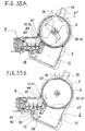
- the developer in the developing apparatus 4 falls from the discharge port 45 of the developing apparatus into the waste developer storage room 71 through the collecting port 77 of the cartridge 5, and is discharged into the waste developer storage room 71 by the discharging screw 78, as shown in Fig. 33B, accomplishing the collection of the waste developer.
- the drive mechanism 8 activates the shutter opening/closing lever 82 to close the discharge shutter 46 of the developing apparatus 4, considering that the whole developer in the developing apparatus 4 have been collected. Then, the drive mechanism 8 stops causing the screw drive shaft 83 to drive the discharging screw 78, and stops driving the developing apparatus 4 by the main motor.
- the drive mechanism 8 When detecting the depression of the exchange switch, the drive mechanism 8 rotates the inner drum 6 leftward to the position shown in Fig. 33E. As a result, the state of the toner supply ports 65 of the inner drum 6 facing the toner injection ports 73 of the outer case 7 is released, the latter ports 73 are closed and the cartridge 5 is locked. In this state, the drive mechanism 8 causes the developing-apparatus drive shaft 81 to rotate the toner supply roller 43 to allow the residual toner at the injection port 44 of the developing apparatus 4 to be collected in the developing apparatus 4, thereby preventing the sputtering of the toner at the time the cartridge 5 is detached therefrom.
- the drive mechanism 8 rotates the inner drum 6 rightward so that the projection 67a of the rotatable engaging portion 67 of the inner drum 6 comes to the mounting hole 90 of the frame 9. This unlocks the cartridge 5 so that it can be detached.
- the cartridge left position detecting switch CP1, new/old discriminating switch CS, a timing sensor TMH and the cartridge rightward position detecting switch CP2 are provided around this drive shaft 80.
- the characteristic detecting switch 84 As shown in Fig. 38.
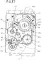
- the drive pulley 86a which is driven by the belt 88a, has a pin that engages with a cam groove of the first cam 86 (see Fig. 43 for the groove).
- the drive pulley 86a directly drives the paddle drive shaft 80a.
- the paddle drive shaft 80a movable rightward and leftward in the diagram, is urged in the right direction in the diagram by a leaf spring 80c.
- This paddle shaft 80a has inclined projections 800 and 801 provided on the respective sides of a center recess 802, as shown in Figs. 42A through 42D.
- the inner drum 6, paddles 64 and 66, the toner supply roller 43, the developer discharge shutter 46 and the discharging screw 78 are sequentially driven by a single motor 85 in the above manner.
- a control section 100 constituted of a microprocessor (MPU), detects the characteristics of the developer and toner from the output of the cartridge characteristic sensor 84 to control a precharging voltage, a developing bias voltage, etc., starts the exchanging sequence according to the output of the new/old discriminating switch CS, and controls the motor 85 based on the outputs of the timing sensor TMH, the cartridge right position detecting switch CP1, the cartridge left position detecting switch CP2 and the shutter opening/closing detecting switch STP.
- MPU microprocessor
- the control section 100 starts the exchanging operation and repeats the forward and reverse rotations of the motor 85 twice. Consequently, the first cam 86 turns in the reverse direction (leftward) to turn the inner drum 6 leftward to the position shown in Figs. 49A and 49B. This releases the state of the toner supply ports 65 of the inner drum 6 facing the tone injection ports 73 of the outer case 7 and closes the latter ports 73. Then, the control section 100 performs the forward and reverse rotations of the motor 85 once to turn the second cam 87 in the reverse direction. Next, the control section 100 turns the motor 85 in the forward direction to cause the forward turning of the second cam 87. As a result, the shutter opening/closing lever 82 is activated to drive the discharging screw 78 and causes the main motor to drive the developing apparatus 4 for one minute.
- the control section 100 repeats the forward and reverse rotations of the motor 85 twice to turn the first cam 86 in the reverse direction (rightward), thereby rotating the inner drum 6 until the drive right position switch CP1 is set on by the projection 67a of the rotatable engaging portion 67 of the inner drum 6, 'as shown in Figs. 51A and 51B. Accordingly, the developer injection ports 63 of the inner drum 6 face the discharge port of the waste toner discharging section 36, as shown in Fig. 33D. The toner supply ports 65 of the inner drum 6 face the toner injection ports 73 of the outer case 7.
- control section 100 repeats the forward and reverse rotations of the motor 85 twice to turn the first cam 86 in the forward direction (rightward). Consequently, the inner drum 6 is rotated rightward so that the projection 67a of the rotatable engaging portion 67 of the inner drum 6 comes to the mounting hole 90 of the frame 9, as shown in Fig. 33F. This unlocks the cartridge 5 so that it can be detached.
- the detachment of the cartridge 5, the exchange of the developer, the supplement of the toner, the rotation of the paddles, etc. can be accomplished by the functions of the cams 86 and 87 by controlling a single motor 85.
Landscapes
- Physics & Mathematics (AREA)
- General Physics & Mathematics (AREA)
- Dry Development In Electrophotography (AREA)
- Cleaning In Electrography (AREA)
Applications Claiming Priority (4)
| Application Number | Priority Date | Filing Date | Title |
|---|---|---|---|
| JP124424/92 | 1992-05-18 | ||
| JP4124424A JP2864182B2 (ja) | 1992-05-18 | 1992-05-18 | 現像装置 |
| JP173131/92 | 1992-06-30 | ||
| JP4173131A JP3014070B2 (ja) | 1992-06-30 | 1992-06-30 | 現像剤カ−トリッジ及びこれを用いた画像形成装置 |
Publications (2)
| Publication Number | Publication Date |
|---|---|
| EP0571177A1 true EP0571177A1 (fr) | 1993-11-24 |
| EP0571177B1 EP0571177B1 (fr) | 1996-08-21 |
Family
ID=26461106
Family Applications (1)
| Application Number | Title | Priority Date | Filing Date |
|---|---|---|---|
| EP93303832A Expired - Lifetime EP0571177B1 (fr) | 1992-05-18 | 1993-05-18 | Cartouche de développateur et appareil de formation d'images utilisant cette cartouche |
Country Status (4)
| Country | Link |
|---|---|
| US (1) | US5541714A (fr) |
| EP (1) | EP0571177B1 (fr) |
| KR (1) | KR970004163B1 (fr) |
| DE (1) | DE69304136T2 (fr) |
Cited By (2)
| Publication number | Priority date | Publication date | Assignee | Title |
|---|---|---|---|---|
| EP0682297A3 (fr) * | 1994-05-12 | 1996-08-21 | Brother Ind Ltd | Dispositif de développement, comprenant un réservoir de toner détachable, pour un appareil d'enregistrement d'images. |
| US5581334A (en) * | 1994-02-07 | 1996-12-03 | Olivetti-Canon Industriale S.P.A. | Electrostatic image developing device having toner flow control and lumps formation prevention ability |
Families Citing this family (18)
| Publication number | Priority date | Publication date | Assignee | Title |
|---|---|---|---|---|
| JPH06337590A (ja) * | 1993-05-31 | 1994-12-06 | Fujitsu Ltd | 現像装置及び画像形成装置 |
| US5809384A (en) * | 1995-11-10 | 1998-09-15 | Mita Industrial Co., Ltd. | Developing device and toner cartridge applied to same |
| JPH09269640A (ja) * | 1996-03-29 | 1997-10-14 | Mita Ind Co Ltd | トナーカートリッジ |
| JP3537293B2 (ja) * | 1996-11-11 | 2004-06-14 | 株式会社リコー | 電子写真装置および感光体ユニット |
| US6771927B2 (en) * | 2002-12-12 | 2004-08-03 | Xerox Corporation | Toner unit drive element for improved insertion |
| US7085507B2 (en) * | 2003-08-25 | 2006-08-01 | Lexmark International, Inc. | Method and apparatus to control waste toner collection in an image forming apparatus |
| US7205738B2 (en) * | 2004-03-24 | 2007-04-17 | Lexmark International, Inc. | Method and apparatus for time-based dc motor commutation |
| US7274903B2 (en) * | 2004-03-25 | 2007-09-25 | Lexmark International, Inc. | Integrated fuser unit and drive system for use in an electrophotographic imaging process |
| JP4176698B2 (ja) * | 2004-10-18 | 2008-11-05 | シャープ株式会社 | 廃現像剤回収装置およびそれを備えた画像形成装置 |
| US7979006B2 (en) * | 2005-02-28 | 2011-07-12 | Brother Kogyo Kabushiki Kaisha | Image forming apparatus and removable cartridge |
| JP4232747B2 (ja) * | 2005-02-28 | 2009-03-04 | ブラザー工業株式会社 | 画像形成装置 |
| JP4635645B2 (ja) * | 2005-02-28 | 2011-02-23 | ブラザー工業株式会社 | 画像形成装置及びトナーカートリッジ |
| US7257363B2 (en) * | 2005-09-22 | 2007-08-14 | Lexmark International, Inc. | Device for moving toner within an image forming device |
| KR101532204B1 (ko) * | 2011-01-24 | 2015-06-29 | 삼성전자 주식회사 | 화상형성장치 |
| US9523947B2 (en) | 2012-09-26 | 2016-12-20 | Lexmark International, Inc. | Time-based commutation method and system for controlling a fuser assembly |
| US8836747B2 (en) | 2012-10-02 | 2014-09-16 | Lexmark International, Inc. | Motor control system and method for a laser scanning unit of an imaging apparatus |
| JP6932955B2 (ja) * | 2017-03-16 | 2021-09-08 | 株式会社リコー | 粉体収納容器、プロセスカートリッジ、及び、画像形成装置 |
| JP7151202B2 (ja) | 2018-06-19 | 2022-10-12 | ブラザー工業株式会社 | 画像形成装置 |
Citations (3)
| Publication number | Priority date | Publication date | Assignee | Title |
|---|---|---|---|---|
| US4565435A (en) * | 1984-06-25 | 1986-01-21 | Xerox Corporation | Apparatus and method for removing developer from the sump of an electrostatic copying or printing machine |
| US5101237A (en) * | 1991-03-22 | 1992-03-31 | International Business Machines Corporation | Toner metering apparatus with pressure equalization |
| US5109254A (en) * | 1989-08-25 | 1992-04-28 | Ricoh Company, Ltd. | Developing apparatus |
Family Cites Families (5)
| Publication number | Priority date | Publication date | Assignee | Title |
|---|---|---|---|---|
| US4768055A (en) * | 1986-06-17 | 1988-08-30 | Mita Industrial Co., Ltd. | Image forming machine having a toner recycling unit |
| JP2546851Y2 (ja) * | 1990-01-19 | 1997-09-03 | 株式会社リコー | 電子写真装置の現像装置 |
| US5243390A (en) * | 1990-06-27 | 1993-09-07 | Minolta Camera Kabushiki Kaisha | Device for conveying developer in a developing device |
| JP2953001B2 (ja) * | 1990-08-28 | 1999-09-27 | ミノルタ株式会社 | トナー供給装置 |
| JP2937445B2 (ja) * | 1990-09-10 | 1999-08-23 | 富士通株式会社 | 現像剤の交換方法及び現像剤交換カートリッジ |
-
1993
- 1993-05-13 US US08/060,971 patent/US5541714A/en not_active Expired - Lifetime
- 1993-05-18 DE DE69304136T patent/DE69304136T2/de not_active Expired - Lifetime
- 1993-05-18 KR KR1019930008455A patent/KR970004163B1/ko not_active Expired - Lifetime
- 1993-05-18 EP EP93303832A patent/EP0571177B1/fr not_active Expired - Lifetime
Patent Citations (3)
| Publication number | Priority date | Publication date | Assignee | Title |
|---|---|---|---|---|
| US4565435A (en) * | 1984-06-25 | 1986-01-21 | Xerox Corporation | Apparatus and method for removing developer from the sump of an electrostatic copying or printing machine |
| US5109254A (en) * | 1989-08-25 | 1992-04-28 | Ricoh Company, Ltd. | Developing apparatus |
| US5101237A (en) * | 1991-03-22 | 1992-03-31 | International Business Machines Corporation | Toner metering apparatus with pressure equalization |
Cited By (2)
| Publication number | Priority date | Publication date | Assignee | Title |
|---|---|---|---|---|
| US5581334A (en) * | 1994-02-07 | 1996-12-03 | Olivetti-Canon Industriale S.P.A. | Electrostatic image developing device having toner flow control and lumps formation prevention ability |
| EP0682297A3 (fr) * | 1994-05-12 | 1996-08-21 | Brother Ind Ltd | Dispositif de développement, comprenant un réservoir de toner détachable, pour un appareil d'enregistrement d'images. |
Also Published As
| Publication number | Publication date |
|---|---|
| DE69304136T2 (de) | 1997-01-09 |
| DE69304136D1 (de) | 1996-09-26 |
| EP0571177B1 (fr) | 1996-08-21 |
| KR970004163B1 (ko) | 1997-03-25 |
| US5541714A (en) | 1996-07-30 |
Similar Documents
| Publication | Publication Date | Title |
|---|---|---|
| EP0577416B1 (fr) | Cartouche de développateur et appareil de formation d'image l'utilisant | |
| EP0571177B1 (fr) | Cartouche de développateur et appareil de formation d'images utilisant cette cartouche | |
| KR100282827B1 (ko) | 토너 병, 토너 공급 시스템 및 이를 사용하는 화상 형성 장치 | |
| JP4750403B2 (ja) | 画像形成装置 | |
| US7738817B2 (en) | Developer supply container and image forming apparatus | |
| JP3833157B2 (ja) | トナー供給容器及び電子写真画像形成装置 | |
| EP1890199A2 (fr) | Appareil de formation d'images et cartouche d'agent de développement | |
| EP2237112B1 (fr) | Corps de stockage de révélateur, unité de formation d'images et appareil de formation d'images | |
| EP0578439B1 (fr) | Cartouche de développateur et appareil de formation d'image l'utilisant | |
| JP4612805B2 (ja) | 画像形成装置 | |
| JP2005326869A (ja) | トナー供給容器及び電子写真画像形成装置 | |
| JP3862745B2 (ja) | トナー供給容器及び電子写真画像形成装置 | |
| JP2003345202A (ja) | 現像剤回収容器及び画像形成装置 | |
| JP6292180B2 (ja) | 画像形成装置 | |
| JPH07325444A (ja) | カラー電子写真装置 | |
| US20030219290A1 (en) | Image formation apparatus and developer collection vessel used therewith | |
| JP3952705B2 (ja) | 画像形成装置 | |
| JP2002014542A (ja) | 廃トナー回収装置 | |
| JP3014070B2 (ja) | 現像剤カ−トリッジ及びこれを用いた画像形成装置 | |
| JPH06250485A (ja) | 画像形成装置 | |
| JPH0418578A (ja) | トナーカートリッジ | |
| JP2000029372A (ja) | 画像形成装置 | |
| JPH04115273A (ja) | 画像形成装置 | |
| JPH0727485Y2 (ja) | 画像形成装置 | |
| JPH09211949A (ja) | トナーカートリッジ |
Legal Events
| Date | Code | Title | Description |
|---|---|---|---|
| PUAI | Public reference made under article 153(3) epc to a published international application that has entered the european phase |
Free format text: ORIGINAL CODE: 0009012 |
|
| AK | Designated contracting states |
Kind code of ref document: A1 Designated state(s): DE FR GB |
|
| 17P | Request for examination filed |
Effective date: 19931118 |
|
| 17Q | First examination report despatched |
Effective date: 19951005 |
|
| GRAH | Despatch of communication of intention to grant a patent |
Free format text: ORIGINAL CODE: EPIDOS IGRA |
|
| GRAH | Despatch of communication of intention to grant a patent |
Free format text: ORIGINAL CODE: EPIDOS IGRA |
|
| GRAA | (expected) grant |
Free format text: ORIGINAL CODE: 0009210 |
|
| AK | Designated contracting states |
Kind code of ref document: B1 Designated state(s): DE FR GB |
|
| PG25 | Lapsed in a contracting state [announced via postgrant information from national office to epo] |
Ref country code: FR Effective date: 19960821 |
|
| REF | Corresponds to: |
Ref document number: 69304136 Country of ref document: DE Date of ref document: 19960926 |
|
| EN | Fr: translation not filed | ||
| PG25 | Lapsed in a contracting state [announced via postgrant information from national office to epo] |
Ref country code: GB Effective date: 19970518 |
|
| PLBE | No opposition filed within time limit |
Free format text: ORIGINAL CODE: 0009261 |
|
| STAA | Information on the status of an ep patent application or granted ep patent |
Free format text: STATUS: NO OPPOSITION FILED WITHIN TIME LIMIT |
|
| 26N | No opposition filed | ||
| GBPC | Gb: european patent ceased through non-payment of renewal fee |
Effective date: 19970518 |
|
| PGFP | Annual fee paid to national office [announced via postgrant information from national office to epo] |
Ref country code: DE Payment date: 20120516 Year of fee payment: 20 |
|
| REG | Reference to a national code |
Ref country code: DE Ref legal event code: R071 Ref document number: 69304136 Country of ref document: DE |
|
| PG25 | Lapsed in a contracting state [announced via postgrant information from national office to epo] |
Ref country code: DE Free format text: LAPSE BECAUSE OF EXPIRATION OF PROTECTION Effective date: 20130522 |