EP0571321A2 - Cadre de fenêtre - Google Patents
Cadre de fenêtre Download PDFInfo
- Publication number
- EP0571321A2 EP0571321A2 EP93810280A EP93810280A EP0571321A2 EP 0571321 A2 EP0571321 A2 EP 0571321A2 EP 93810280 A EP93810280 A EP 93810280A EP 93810280 A EP93810280 A EP 93810280A EP 0571321 A2 EP0571321 A2 EP 0571321A2
- Authority
- EP
- European Patent Office
- Prior art keywords
- frame
- section
- wood
- rebated
- finger
- Prior art date
- Legal status (The legal status is an assumption and is not a legal conclusion. Google has not performed a legal analysis and makes no representation as to the accuracy of the status listed.)
- Granted
Links
- 210000001145 finger joint Anatomy 0.000 claims abstract description 26
- 239000002023 wood Substances 0.000 claims description 22
- 238000004519 manufacturing process Methods 0.000 claims 1
- 238000006073 displacement reaction Methods 0.000 abstract description 5
- 238000005246 galvanizing Methods 0.000 description 4
- 239000007787 solid Substances 0.000 description 4
- 230000008961 swelling Effects 0.000 description 4
- 238000005470 impregnation Methods 0.000 description 3
- 238000004026 adhesive bonding Methods 0.000 description 2
- 238000005304 joining Methods 0.000 description 2
- 230000000149 penetrating effect Effects 0.000 description 2
- 238000003825 pressing Methods 0.000 description 2
- 230000002745 absorbent Effects 0.000 description 1
- 239000002250 absorbent Substances 0.000 description 1
- 238000000034 method Methods 0.000 description 1
- 238000000638 solvent extraction Methods 0.000 description 1
Images


Classifications
-
- B—PERFORMING OPERATIONS; TRANSPORTING
- B27—WORKING OR PRESERVING WOOD OR SIMILAR MATERIAL; NAILING OR STAPLING MACHINES IN GENERAL
- B27M—WORKING OF WOOD NOT PROVIDED FOR IN SUBCLASSES B27B - B27L; MANUFACTURE OF SPECIFIC WOODEN ARTICLES
- B27M3/00—Manufacture or reconditioning of specific semi-finished or finished articles
- B27M3/0013—Manufacture or reconditioning of specific semi-finished or finished articles of composite or compound articles
- B27M3/0086—Manufacture or reconditioning of specific semi-finished or finished articles of composite or compound articles characterised by connecting using glue
-
- E—FIXED CONSTRUCTIONS
- E06—DOORS, WINDOWS, SHUTTERS, OR ROLLER BLINDS IN GENERAL; LADDERS
- E06B—FIXED OR MOVABLE CLOSURES FOR OPENINGS IN BUILDINGS, VEHICLES, FENCES OR LIKE ENCLOSURES IN GENERAL, e.g. DOORS, WINDOWS, BLINDS, GATES
- E06B3/00—Window sashes, door leaves, or like elements for closing wall or like openings; Layout of fixed or moving closures, e.g. windows in wall or like openings; Features of rigidly-mounted outer frames relating to the mounting of wing frames
- E06B3/96—Corner joints or edge joints for windows, doors, or the like frames or wings
- E06B3/984—Corner joints or edge joints for windows, doors, or the like frames or wings specially adapted for frame members of wood or other material worked in a similar way
Definitions
- the invention relates to a window frame with frame legs, made of wood, which each have a rebated section on their inner sides and which are connected to each other in each corner of the frame.
- the window frame can be both a window frame and a casement.
- the object of the invention is to design the connections of the components of the window frame with one another in such a way that the components automatically bring themselves into the desired end position during the pressing and that there are rigid and dimensionally stable connections.
- a window frame of the specified type in which the frame legs are connected to one another in the corners of the frame by means of a wedge-jointing, the section of which in the region of the rebated sections runs at least approximately in miter, each wedge-jointing following the approximately mitred section has a tangent to this arcuate section is known for example from CH-PS 546 877. According to this, the arcuate section of each finger joint is to run symmetrically with respect to the longitudinal central plane of the solid wood section of one of the frame legs, which is perpendicular to the frame plane.
- each finger joint has a center of curvature which lies in the longitudinal median plane of the solid wood section of the one frame leg. When the frame legs are pressed together, they are centered on the center of curvature. It can be on the outside of the frame leg, where the arcuate section the finger jointing ends, unsightly and disruptive displacements of the finger joint occur.
- the window frame according to the invention is characterized in that the arcuate section of each finger jointing extends in each case over an angle of approximately 45 °, so that the tangent to the outer end of the arcuate section is approximately perpendicular to one of the frame legs.
- the finger jointing between the outer end of the arcuate section and the outside of the frame leg also contains a rectilinear section which is approximately perpendicular to the longitudinal direction of the frame leg.
- a window frame can also contain at least one subdivision element in the form of a set timber or a fighter (in the frame) or in the form of a rung (in the casement frame), which subdivision element extends from one of the frame legs to the opposite frame leg or to another subdivision element extends.
- the object of the invention is achieved in that the dividing element is connected at both ends by means of a spline joint, which has curved sections in the region of the rebated sections.
- partitioning elements were usually connected with a slot and pin, with dowels or with screws. Problems due to shrinkage and swelling of the wood could not be avoided.
- a method according to the invention for producing a window frame from beam-shaped wooden elements is characterized in that interlocking finger joints are incorporated into the ends of the beam-shaped wooden elements so that the finger joints are then impregnated and that the ends of each wooden element provided with the finger joints and impregnated are subsequently glued to another of the wooden elements.
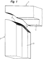
- FIG. 1 and 2 schematically show the end portions of two mutually perpendicular frame legs 1 and 2 of a wooden window frame, which form a corner of the frame.
- the window frame can be both a casement frame and a window frame.
- Each frame leg has a rebated section 1.1 or 2.1 on its inner side with respect to the frame.
- the end faces of the frame legs that are to be connected to one another are each provided with a spline joint.
- the finger jointing contains a section 3 which runs in a miter. This section 3 is followed by an arcuate section 4 which extends tangentially to section 3.
- the arcuate section extends over an angle ⁇ of approximately 45 °, so that the tangent t to the outer end E of the arcuate section 4 of the finger joint is approximately perpendicular to the longitudinal direction and thus to the outside A of the frame leg 2.
- the arcuate section 4 expediently runs according to a circular arc with a center of curvature K.
- the wedge galvanizing contains a rectilinear section 5 which ends in the outside A of the frame leg 2 and is approximately perpendicular to this outside A. .
- the two finger joints to be connected are impregnated.
- the impregnation is very effective because the surfaces to be joined are largely in the end grain and are therefore absorbent. The areas are also enlarged by the integrated finger joints. After impregnation, the surfaces are glued together.
- the risk of moisture penetrating into the wood and thus swelling and shrinking of the wood is greatly reduced in the finished window frame. The connection of the two frame legs therefore remains stable over a long service life.
- FIG. 3 shows in the same representation as FIG. 2 the ends of two frame legs 11 and 12, which form a corner of a window frame.
- the frame legs 11 and 12 each have a rebated section 11.1 and 12.1 on their inner sides.
- the end faces of the frame legs 11 and 12 are connected to one another by means of a wedge-shaped galvanization which, in the region of the rebated sections, again contains the essentially mitred section 3 to which the arcuate section 4 adjoins tangentially.
- the arcuate section 4 extends over the angle ⁇ of approximately 45 °, the tangent t to the outer end E is approximately perpendicular to the frame leg 12.
- the wedge galvanizing following the outer end E of the arcuate section 4 contains a rectilinear section 15 which is approximately perpendicular to the frame leg 12 and which is longer than the straight line Section 5 in Fig. 2.
- the outer end of the finger-jointing which lies in the outer surface A of one frame leg 2 or 12, is approximately perpendicular to this outer side surface A. For this reason, forces which are applied when the frame legs 1 and 2 or 11 and 12 are pressed together do not lead to displacements in the finger jointing in the outer side surface A.
- FIGS. 4 to 7 show different window frames, each with four frame legs 21, 22, 23, 24 made of wood, which are connected to one another in the corners of the frame as described above with reference to FIGS. 1 to 3.
- Each of the frames additionally contains at least one dividing element, likewise made of wood and provided with cut-offs on both sides, which extends from one of the frame legs to an opposite frame leg or to another dividing element.
- Fig. 4 shows a frame with a set wood 25 which extends from the upper frame leg 21 to the lower frame leg 23.
- the frame shown in FIGS. 5 and 6 each contain a fighter 26 which extends from the left frame leg 22 to the right frame leg 24.
- FIG. 6 also contains a second dividing element in the form of a set wood 27, which extends from the upper frame leg 21 to the fighter 26.
- FIG. 7 shows a sash frame with two horizontal rungs 28 and 29, which each extend from the left frame leg 22 to the right frame leg 24. All of these subdivision elements 25, 26, 27, 28, 29 are each connected at their two ends by means of a wedge galvanizing which has arcuate sections in the region of the rebated sections, as explained below with reference to FIGS. 8 and 9 for one end of a subdivision element becomes.
- FIGS. 8 and 9 schematically show an end section of a dividing element 30, which, as explained above, can be a set timber, a fighter or a rung, and a section of a frame leg 31.
- the element 31 could also be a second dividing element.
- the frame leg 31 has a rebated section 31.1 facing the dividing element 30, and the dividing element 30 has rebated sections 30.1 and 30.2 on both sides. Finger joints are milled into the end face of the dividing element 30 and into the side of the frame leg 31 provided with the cut-off 31.1.
- the finger joints in the area of the rebated sections 30.1, 30.2, 31.1 contain two arcuate sections 32 and 33 which extend to a depth t into the solid wood part of the frame leg 31.
- the depth t is at least as great as the tine depth of the finger joints.
- the two arcuate sections 32 and 33 of the finger jointing are connected to one another by a section 34 which extends in a straight line in the solid wood part of the frame leg 31 and which is tangential to the arcuate sections 32 and 33 connects.
- the straight section 34 is parallel to the longitudinal direction of the frame leg 31 and has a length which can vary depending on the width of the dividing element 30.
- the finger joints are impregnated on both parts. After impregnation, the finger joints are glued together. When pressing the subdivision element 30 against the frame leg 31, the subdivision element 30 automatically brings itself into the desired end position with respect to the frame leg 31 thanks to the shape of the finger joints described.
- impregnating the finger joints before gluing there is a risk of moisture penetrating into the finished window frame Wood, and thus the risk of the wood swelling and shrinking, is greatly reduced. The connection therefore remains stable over a long service life.
- FIG. 10 shows, in the same representation as FIG. 9, an end section of a dividing element 40 and a section of a frame leg (or other dividing element) 41.
- the frame leg 41 has a rebated section 41.1
- the dividing element 40 has rebated sections 40.1 or respectively on both sides 40.2.
- the parts shown in FIG. 10 differ from those shown in FIG. 9 only in that in FIG. 10 the rebated sections 40.1 and 40.2 of the dividing element 40 are wider than the rebated sections 30.1 and 30.2 in FIG. 9, and also wider than the rebated section 41.1.
- the wedge galvanizing 32, 33, 34 this results in the sections 40.1 and 40.2 at the free ends of the arcuate sections 32 and 33 in each case a shoulder 42 or 43.
Landscapes
- Engineering & Computer Science (AREA)
- Life Sciences & Earth Sciences (AREA)
- Structural Engineering (AREA)
- Wood Science & Technology (AREA)
- Forests & Forestry (AREA)
- Civil Engineering (AREA)
- Manufacturing & Machinery (AREA)
- Door And Window Frames Mounted To Openings (AREA)
- Joining Of Corner Units Of Frames Or Wings (AREA)
- Special Wing (AREA)
- Wing Frames And Configurations (AREA)
- Mirrors, Picture Frames, Photograph Stands, And Related Fastening Devices (AREA)
- Glass Compositions (AREA)
Applications Claiming Priority (3)
| Application Number | Priority Date | Filing Date | Title |
|---|---|---|---|
| CH1616/92A CH685304A5 (de) | 1992-05-20 | 1992-05-20 | Fensterrahmen. |
| CH161692 | 1992-05-20 | ||
| CH1616/92 | 1992-05-20 |
Publications (3)
| Publication Number | Publication Date |
|---|---|
| EP0571321A2 true EP0571321A2 (fr) | 1993-11-24 |
| EP0571321A3 EP0571321A3 (en) | 1996-09-11 |
| EP0571321B1 EP0571321B1 (fr) | 1999-10-20 |
Family
ID=4214604
Family Applications (1)
| Application Number | Title | Priority Date | Filing Date |
|---|---|---|---|
| EP93810280A Expired - Lifetime EP0571321B1 (fr) | 1992-05-20 | 1993-04-16 | Cadre de fenêtre |
Country Status (4)
| Country | Link |
|---|---|
| EP (1) | EP0571321B1 (fr) |
| AT (1) | ATE185874T1 (fr) |
| CH (1) | CH685304A5 (fr) |
| DE (1) | DE59309836D1 (fr) |
Cited By (4)
| Publication number | Priority date | Publication date | Assignee | Title |
|---|---|---|---|---|
| EP0738570A1 (fr) * | 1995-04-20 | 1996-10-23 | Fentech AG | Procédé d'assemblage d'éléments de bois |
| EP1895088A1 (fr) * | 2006-08-31 | 2008-03-05 | Leitz GmbH & Co. KG | Elément de fenêtre et outil pour le traitement de bords de fenêtre |
| ITMI20090090A1 (it) * | 2009-01-27 | 2010-07-28 | Radaelli Angelo S A S Di Renata Va Gni Radaelli & | Struttura di semilavorato per la realizzazione di serramenti e suo metodo di fabbricazione. |
| CN105909143A (zh) * | 2016-04-18 | 2016-08-31 | 魏文忠 | 一种木门、一种木窗以及木门窗的角部连接结构 |
Families Citing this family (2)
| Publication number | Priority date | Publication date | Assignee | Title |
|---|---|---|---|---|
| DE202008014630U1 (de) | 2008-11-04 | 2009-02-19 | Otmar Döpfner Besitz GmbH & Co. KG | Blendrahmen (Zarge) für Holzfenster |
| CN102587802A (zh) * | 2012-03-23 | 2012-07-18 | 上海杰阳实业有限公司 | 一种木质门窗框的角部对接结构 |
Family Cites Families (3)
| Publication number | Priority date | Publication date | Assignee | Title |
|---|---|---|---|---|
| CH546877A (de) * | 1972-04-27 | 1974-03-15 | Mueller Jost Fensterfabrik | Eckverbindung am rahmen eines fenster- oder tuerfluegels. |
| CH545904A (fr) * | 1972-04-27 | 1974-02-15 | ||
| DE3903548A1 (de) * | 1989-02-07 | 1990-08-09 | Hugo Selnar | Holz-bauteil, verfahren zur herstellung eines holz-bauteils und profilleiste zur verbindung mit einem derartigen holz-bauteil |
-
1992
- 1992-05-20 CH CH1616/92A patent/CH685304A5/de not_active IP Right Cessation
-
1993
- 1993-04-16 AT AT93810280T patent/ATE185874T1/de not_active IP Right Cessation
- 1993-04-16 EP EP93810280A patent/EP0571321B1/fr not_active Expired - Lifetime
- 1993-04-16 DE DE59309836T patent/DE59309836D1/de not_active Expired - Fee Related
Cited By (6)
| Publication number | Priority date | Publication date | Assignee | Title |
|---|---|---|---|---|
| EP0738570A1 (fr) * | 1995-04-20 | 1996-10-23 | Fentech AG | Procédé d'assemblage d'éléments de bois |
| EP1895088A1 (fr) * | 2006-08-31 | 2008-03-05 | Leitz GmbH & Co. KG | Elément de fenêtre et outil pour le traitement de bords de fenêtre |
| ITMI20090090A1 (it) * | 2009-01-27 | 2010-07-28 | Radaelli Angelo S A S Di Renata Va Gni Radaelli & | Struttura di semilavorato per la realizzazione di serramenti e suo metodo di fabbricazione. |
| EP2226457A3 (fr) * | 2009-01-27 | 2010-11-17 | Radaelli Angelo S.a.s di Renata Vagni Radaelli & C | Construction de produit semi-fini pour fabriquer des cadres de fenêtre et de porte et procédé associé |
| CN105909143A (zh) * | 2016-04-18 | 2016-08-31 | 魏文忠 | 一种木门、一种木窗以及木门窗的角部连接结构 |
| EP3235998A1 (fr) * | 2016-04-18 | 2017-10-25 | Wei, Wenzhong | Fenêtre de bois, porte en bois et joint d'angle pour portes et fenêtres en bois |
Also Published As
| Publication number | Publication date |
|---|---|
| ATE185874T1 (de) | 1999-11-15 |
| EP0571321B1 (fr) | 1999-10-20 |
| DE59309836D1 (de) | 1999-11-25 |
| CH685304A5 (de) | 1995-05-31 |
| EP0571321A3 (en) | 1996-09-11 |
Similar Documents
| Publication | Publication Date | Title |
|---|---|---|
| EP0571321B1 (fr) | Cadre de fenêtre | |
| DE1960704A1 (de) | Tuerrahmen | |
| DE2753289A1 (de) | Fensterrahmen aus auf gehrung geschnittenen, an den gehrungsflaechen mit minizinken versehenen und miteinander verleimten rahmenschenkeln | |
| DE102012000515A1 (de) | Rahmeneckverbindung für Fenster und/oder Türen | |
| DE2654398A1 (de) | Anordnung eines isolierglaseinsatzes in einem urspruenglich einfach verglasten fenster | |
| DE4017608C2 (de) | Bausatz für Fenster | |
| DE2717637A1 (de) | Tuer- oder plattenelement mit einem rahmen | |
| DE3216177C2 (de) | Treibstangenbeschlag mit einer Eckumlenkung für in einer am Flügelrahmen umlaufenden Nut geführte Treibstangen | |
| CH545904A (fr) | ||
| DE2145226A1 (de) | Holzprofilmaterial, insbesondere fuer tuer- und fensterrahmen | |
| DE2145902A1 (de) | Verbindungsanordnung zur Verbindung mindestens zweier plattenförmiger Konstruk tionsteile | |
| AT402428B (de) | Eckverbindung für einen holzrahmen eines fensters oder einer tür | |
| EP0769259B1 (fr) | Joint d'angle | |
| DE9212415U1 (de) | Profilleiste mit darauf blockierten Teil, dazu verwendete Blockierschraube und mit einem derartigen Proflleiste versehenes Kippfenster | |
| AT16744U1 (de) | Wandelement für einen Holzrahmenbau | |
| DE7230375U (de) | Eckverbindungswinkel für auf Gehrung zugeschnittene Metall-Hohlprofile | |
| DE19540568A1 (de) | Eckverbindung für Fensterrahmen und dergleichen aus Holz | |
| DE8711492U1 (de) | Verbundprofil für Rahmenschenkel oder -sprossen | |
| AT405545B (de) | Zusammensetzbare bauelemente mit einer lösbaren fügeverbindung | |
| AT381979B (de) | Platte, insbesondere tuerblatt | |
| DE3526729A1 (de) | Verbindung zwischen zwei hohlprofilen, insbesondere fuer eine duschabtrennung | |
| DE7437431U (de) | Türblatt | |
| DE8711080U1 (de) | Konstruktionselement für den Aufbau eines Hauses, einer Hütte o.dgl. in Bohlenfachwerk-Bauweise | |
| DE2452873A1 (de) | Zarge | |
| DE9404316U1 (de) | Rahmen, insbesondere Blend- oder Flügelrahmen für Fenster |
Legal Events
| Date | Code | Title | Description |
|---|---|---|---|
| PUAI | Public reference made under article 153(3) epc to a published international application that has entered the european phase |
Free format text: ORIGINAL CODE: 0009012 |
|
| AK | Designated contracting states |
Kind code of ref document: A2 Designated state(s): AT DE FR IT |
|
| PUAL | Search report despatched |
Free format text: ORIGINAL CODE: 0009013 |
|
| AK | Designated contracting states |
Kind code of ref document: A3 Designated state(s): AT DE FR IT |
|
| 17P | Request for examination filed |
Effective date: 19970129 |
|
| 17Q | First examination report despatched |
Effective date: 19981001 |
|
| GRAG | Despatch of communication of intention to grant |
Free format text: ORIGINAL CODE: EPIDOS AGRA |
|
| GRAG | Despatch of communication of intention to grant |
Free format text: ORIGINAL CODE: EPIDOS AGRA |
|
| GRAG | Despatch of communication of intention to grant |
Free format text: ORIGINAL CODE: EPIDOS AGRA |
|
| GRAH | Despatch of communication of intention to grant a patent |
Free format text: ORIGINAL CODE: EPIDOS IGRA |
|
| GRAH | Despatch of communication of intention to grant a patent |
Free format text: ORIGINAL CODE: EPIDOS IGRA |
|
| GRAA | (expected) grant |
Free format text: ORIGINAL CODE: 0009210 |
|
| AK | Designated contracting states |
Kind code of ref document: B1 Designated state(s): AT DE FR IT |
|
| REF | Corresponds to: |
Ref document number: 185874 Country of ref document: AT Date of ref document: 19991115 Kind code of ref document: T |
|
| REF | Corresponds to: |
Ref document number: 59309836 Country of ref document: DE Date of ref document: 19991125 |
|
| ITF | It: translation for a ep patent filed | ||
| ET | Fr: translation filed | ||
| PLBE | No opposition filed within time limit |
Free format text: ORIGINAL CODE: 0009261 |
|
| STAA | Information on the status of an ep patent application or granted ep patent |
Free format text: STATUS: NO OPPOSITION FILED WITHIN TIME LIMIT |
|
| 26N | No opposition filed | ||
| PGFP | Annual fee paid to national office [announced via postgrant information from national office to epo] |
Ref country code: FR Payment date: 20050425 Year of fee payment: 13 |
|
| PGFP | Annual fee paid to national office [announced via postgrant information from national office to epo] |
Ref country code: AT Payment date: 20060412 Year of fee payment: 14 |
|
| PGFP | Annual fee paid to national office [announced via postgrant information from national office to epo] |
Ref country code: DE Payment date: 20060413 Year of fee payment: 14 |
|
| PGFP | Annual fee paid to national office [announced via postgrant information from national office to epo] |
Ref country code: IT Payment date: 20060430 Year of fee payment: 14 |
|
| REG | Reference to a national code |
Ref country code: FR Ref legal event code: ST Effective date: 20061230 |
|
| PG25 | Lapsed in a contracting state [announced via postgrant information from national office to epo] |
Ref country code: DE Free format text: LAPSE BECAUSE OF NON-PAYMENT OF DUE FEES Effective date: 20071101 |
|
| PG25 | Lapsed in a contracting state [announced via postgrant information from national office to epo] |
Ref country code: AT Free format text: LAPSE BECAUSE OF NON-PAYMENT OF DUE FEES Effective date: 20070416 |
|
| PG25 | Lapsed in a contracting state [announced via postgrant information from national office to epo] |
Ref country code: FR Free format text: LAPSE BECAUSE OF NON-PAYMENT OF DUE FEES Effective date: 20060502 |
|
| PG25 | Lapsed in a contracting state [announced via postgrant information from national office to epo] |
Ref country code: IT Free format text: LAPSE BECAUSE OF NON-PAYMENT OF DUE FEES Effective date: 20070416 |