EP0571426B1 - Nettoyage de pieces comportant des residus organiques - Google Patents
Nettoyage de pieces comportant des residus organiques Download PDFInfo
- Publication number
- EP0571426B1 EP0571426B1 EP92904002A EP92904002A EP0571426B1 EP 0571426 B1 EP0571426 B1 EP 0571426B1 EP 92904002 A EP92904002 A EP 92904002A EP 92904002 A EP92904002 A EP 92904002A EP 0571426 B1 EP0571426 B1 EP 0571426B1
- Authority
- EP
- European Patent Office
- Prior art keywords
- pressure vessel
- liquefied
- pressure
- supercritical gas
- process according
- Prior art date
- Legal status (The legal status is an assumption and is not a legal conclusion. Google has not performed a legal analysis and makes no representation as to the accuracy of the status listed.)
- Expired - Lifetime
Links
Images
Classifications
-
- B—PERFORMING OPERATIONS; TRANSPORTING
- B08—CLEANING
- B08B—CLEANING IN GENERAL; PREVENTION OF FOULING IN GENERAL
- B08B3/00—Cleaning by methods involving the use or presence of liquid or steam
- B08B3/04—Cleaning involving contact with liquid
- B08B3/10—Cleaning involving contact with liquid with additional treatment of the liquid or of the object being cleaned, e.g. by heat, by electricity or by vibration
- B08B3/12—Cleaning involving contact with liquid with additional treatment of the liquid or of the object being cleaned, e.g. by heat, by electricity or by vibration by sonic or ultrasonic vibrations
-
- B—PERFORMING OPERATIONS; TRANSPORTING
- B08—CLEANING
- B08B—CLEANING IN GENERAL; PREVENTION OF FOULING IN GENERAL
- B08B3/00—Cleaning by methods involving the use or presence of liquid or steam
- B08B3/04—Cleaning involving contact with liquid
- B08B3/10—Cleaning involving contact with liquid with additional treatment of the liquid or of the object being cleaned, e.g. by heat, by electricity or by vibration
- B08B3/102—Cleaning involving contact with liquid with additional treatment of the liquid or of the object being cleaned, e.g. by heat, by electricity or by vibration with means for agitating the liquid
- B08B3/104—Cleaning involving contact with liquid with additional treatment of the liquid or of the object being cleaned, e.g. by heat, by electricity or by vibration with means for agitating the liquid using propellers
-
- B—PERFORMING OPERATIONS; TRANSPORTING
- B08—CLEANING
- B08B—CLEANING IN GENERAL; PREVENTION OF FOULING IN GENERAL
- B08B7/00—Cleaning by methods not provided for in a single other subclass or a single group in this subclass
- B08B7/0021—Cleaning by methods not provided for in a single other subclass or a single group in this subclass by liquid gases or supercritical fluids
-
- B—PERFORMING OPERATIONS; TRANSPORTING
- B08—CLEANING
- B08B—CLEANING IN GENERAL; PREVENTION OF FOULING IN GENERAL
- B08B7/00—Cleaning by methods not provided for in a single other subclass or a single group in this subclass
- B08B7/0064—Cleaning by methods not provided for in a single other subclass or a single group in this subclass by temperature changes
- B08B7/0092—Cleaning by methods not provided for in a single other subclass or a single group in this subclass by temperature changes by cooling
-
- C—CHEMISTRY; METALLURGY
- C23—COATING METALLIC MATERIAL; COATING MATERIAL WITH METALLIC MATERIAL; CHEMICAL SURFACE TREATMENT; DIFFUSION TREATMENT OF METALLIC MATERIAL; COATING BY VACUUM EVAPORATION, BY SPUTTERING, BY ION IMPLANTATION OR BY CHEMICAL VAPOUR DEPOSITION, IN GENERAL; INHIBITING CORROSION OF METALLIC MATERIAL OR INCRUSTATION IN GENERAL
- C23G—CLEANING OR DE-GREASING OF METALLIC MATERIAL BY CHEMICAL METHODS OTHER THAN ELECTROLYSIS
- C23G5/00—Cleaning or de-greasing metallic material by other methods; Apparatus for cleaning or de-greasing metallic material with organic solvents
Definitions
- the invention relates to a method for cleaning workpieces which have organic residues, using a compressed gas which is introduced under pressure into a pressure container loaded with the workpieces.
- a gas compressed to its supercritical pressure or above is placed in a pressure container on the workpieces to be cleaned headed.
- the temperature of the gas compressed in this way is then changed in various steps, starting from a point close to the critical temperature, in order to influence the solution properties of the gas phase. Before each change, the temperature is kept constant for a certain time interval.
- the cleaning of the workpieces can also be supported by adding a liquid such as ion-free water to the compressed gas, a chemically reactive one Substance or sound or radiation energy can be introduced.
- the measures described, which support the cleaning of the workpieces require technically complex additional devices and are also not very effective. The effort involved is not justified by increased cleaning success.
- the method according to WO 90 06 189 also requires a high level of control engineering.
- the individual steps in which the temperature is changed follow at intervals of about 10 minutes.
- the temperature must be kept constant. It must therefore be ensured that a new temperature is set in a large pressure vessel and then kept constant within a very short time.
- the required complex equipment which is not explained in WO 90 06 189, makes such a cleaning process less attractive for industrial use.
- the invention is therefore based on the object of developing a method for cleaning workpieces contaminated with organic residues using a compressed gas which avoids the abovementioned disadvantages and increases the cleaning success in an economical manner.
- This object is achieved in that a liquefied or supercritical gas is circulated in the pressure vessel during the cleaning process.
- the method according to the invention represents a simple measure which considerably supports the cleaning process.
- the fluid understood as liquefied or supercritical gas, is circulated in the pressure vessel, for example by rotating a bladed impeller.
- the onset of fluid flow in the pressure vessel causes a constant exchange of pure fluid loaded with dissolved impurities. As a result, the organic residues adhering to the surfaces of the workpieces can gradually be completely removed.
- the speed of the circulation is advantageously changed during the cleaning process.
- This change can be made, for example, by cyclically changing the speed of an impeller that causes the circulation.
- the suction and pressure areas of the fluid forming during the circulation change in their cross section, and that at the same time the velocity distribution of the fluid can be influenced. This measure prevents that in Form pressure vessel areas in which the fluid would not circulate at a constant speed of the impeller.
- Suitable fluids for removing organic residues are, for example, noble gases such as helium or argon, hydrocarbons, e.g. Alkanes such as methane, ethane or propane, or alkenes such as ethene or propene, as well as trifluoromethane, carbon dioxide, nitrous oxide and sulfur hexafluoride.
- noble gases such as helium or argon
- hydrocarbons e.g. Alkanes such as methane, ethane or propane
- alkenes such as ethene or propene
- trifluoromethane carbon dioxide, nitrous oxide and sulfur hexafluoride
- Carbon dioxide has proven to be a particularly suitable fluid in the method according to the invention, since it has the following advantages:
- Carbon dioxide is not flammable or explosive, large quantities of carbon dioxide are inexpensively available as a by-product of industrial processes, carbon dioxide is less polluting than other solvents and carbon dioxide is chemically inert.
- the thermodynamic properties of carbon dioxide meet the process according to the invention.
- a suitable measure when carrying out the method according to the invention is to keep the temperature of the liquefied or supercritical gas in the pressure vessel constant during the cleaning process.
- the suitable parameters, temperature and pressure of the fluid for removing the organic residues are first determined in preliminary tests. These parameters are then kept constant during the cleaning process.
- part of the liquefied or supercritical gas is continuously withdrawn from the pressure vessel, passed through a heat exchanger and then returned to the pressure vessel. Heating of the fluid, i.e. of the compressed gas may be necessary for long-term cleaning processes in non-heat-insulated pressure vessels, on the other hand cooling of the fluid may be necessary especially in heat-insulated vessels if the energy supplied for the circulation of the fluid warms the fluid.
- the heat exchange of the fluid is of course also suitable for sweeping over a certain temperature range during the cleaning process, should this be necessary.
- an inadmissible pressure increase can be prevented by using a pressure relief valve or an overflow regulator on the pressure vessel.
- the fluid contaminated with the organic residues must be removed from the pressure vessel, and then the cleaned workpieces are removed.
- the potential stress energy of the liquefied or supercritical gas that is released during expansion is used to drive a turbine.
- This measure allows part of the energy used for the cleaning process to be recovered and the energy efficiency of the cleaning system to be increased.
- the organic residues are separated from at least part of the liquefied or supercritical gas containing the organic residues and the remaining part is used together with pure liquefied or supercritical gas for a further cleaning process.
- the fluid mass in the pressure vessel can be used for several cleaning processes before it is saturated with the organic residues. It is therefore sufficient to replace only a part of the fluid used with pure fluid after each cleaning operation without noticeably reducing the cleaning capacity and speed. This measure sensibly limits the consumption and the effort required to provide the amount of fluid required for cleaning.
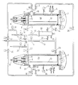
- a suitable device for carrying out the method according to the invention with a cylindrical pressure vessel, which has inlet and outlet lines for compressed gases is characterized in that a first cylindrical pressure vessel contains an impeller mounted on its axis within the pressure vessel, that the first pressure vessel with an analog equipped second pressure vessel is connected via valve-provided lines, that a pump is arranged in one of the connecting lines and a heat exchanger is arranged in this or another connecting line, the heat exchanger and the pump being connected to each pressure vessel by additional lines, and that each pressure vessel is connected to one or more storage containers for compressed gases by further lines.
- Each pressure vessel 38, 39 contains an impeller 6 which causes the compressed gas to circulate and which is separated from the rest of the interior of the pressure vessel 38, 39 by a protective grille 5.
- the impeller 6 is driven outside the pressure container 38, 39 via the shaft 9 and is mounted in a stuffing box 8.
- the pressure vessel 38, 39 there is a fixedly mounted guide rail 12 for a pipe slide on which the workpieces to be cleaned are located.
- the pressure vessel 38, 39 is firmly closed by a high-pressure lid 7.
- Each pressure vessel 38, 39 also contains a pressure measuring device 3, 34 and safety valve devices 4, 35 as well as a level probe 10, 31 and a pressure switch 11, 32.
- the pressure vessels 38, 39 are connected to one another by several lines.
- a direct connecting line contains two shut-off ball valves 2, 33 and a motor-driven control valve 29.
- a heat exchanger 20 is connected to the pressure vessel 38 via lines via the motor-driven control valves 13, 15, 14 and to the pressure vessel 39 via the control valves 27, 15, 28.
- This heat exchanger 20 contains a temperature controller 21 and a safety valve 22.
- a pump 19 is connected to the pressure vessel 38 via lines via the motor-driven control valves 13, 17, 14 and to the pressure vessel 39 via the control valves 27, 17, 28.
- a safety valve 23 is also fitted in the pump line.
- both pressure vessels 38, 39 are connected to one another by lines via the heat exchanger 20 and the control valves 13, 15, 28 and via the pump 19 and the control valves 13, 17, 28.
- a storage container (not shown in the drawing) is used for a compressed gas, in which the latter is compressed under pressure and partly liquefied.
- the cleaning fluid in the gaseous phase can be removed from the upper part of this storage container, and in the liquid phase from the lower part of this storage container and introduced into the two pressure containers 38, 39.
- the gaseous fluid can be passed via the heat exchanger 20 via the control valves 16, 15, 14 into the pressure vessel 38 and via the control valves 16, 15, 28 into the pressure vessel 39.
- the liquid fluid is fed via the pump 19 via the control valves 18, 17, 14 to the pressure vessel 38 and via the control valves 18, 17, 28 to the pressure vessel 39.
- cleaning fluid can be returned from the pressure container 38 to the storage container.
- gaseous fluid can be returned to the reservoir via the overflow regulator 1 and the control valve 36 and liquid fluid via the overflow regulator 1 and the control valve 37.
- cleaning fluid can be returned from the pressure container 39 to the storage container.
- the device according to the invention contains a ventilation system in which the dissolved organic residues are separated from the fluid by relaxing.
- the fluid can also be directed into a turbine, which makes part of the energy released during the relaxation process available again by converting this energy into rotational energy and using the latter to generate electricity.
- This ventilation system is connected via a probe for liquid fluid 26 and a motor-driven control valve 25 to the line system between the two pressure vessels 38, 39.
- used fluid can be conducted from the pressure vessels 38, 39 into the ventilation system.
- the method according to the invention is used to clean copper pipes that have just been produced, the surfaces of which are coated with drawing grease during the manufacturing process.
- About 700 to 800 copper tubes are loaded onto a tube slide and these are then moved on the guide rails 12 into the two pressure vessels 38, 39. Then the high pressure cover 7 are closed.
- carbon dioxide is used as the fluid, which is removed from a storage container under pressure at a room temperature of approximately 298 ° Kelvin.
- the carbon dioxide flows in gaseous form through the lines when the control valves 16, 15 and 14 are open into the pressure vessel 38 until pressure equalization with the reservoir has been established.
- the temperature of the gas is kept constant by the heat exchanger 20 to approximately 298 ° Kelvin.
- the pressure of the carbon dioxide gas at this temperature is then about 64 bar in the pressure vessel 38. A cooling of the gas should be prevented, as this leads to the stopping of the oil-like residues adhering to the pipes and thereby the Cleaning process would complicate.
- the pressure vessel 38 is now biased. Now liquid carbon dioxide can be passed into the pressure vessel 38 without the liquefied gas expanding.
- the connection to the upper part of the storage container is closed, the control valves 18, 17 and 14 are opened and liquid carbon dioxide from the lower part of the storage container is passed via the pump 19 into the pressure container 38.
- the inflowing liquid pushes the carbon dioxide gas back out of the pressure vessel 38 via the overflow regulator 1 into the storage vessel with the control valve 36 open.
- the level probe 10 switches off the pump 19 when the desired level is reached.
- the pressure vessel 38 is now filled with liquid carbon dioxide.
- good cleaning results were achieved at temperatures between 298 ° Kelvin and 304 ° Kelvin, the pressure was slightly above the corresponding vapor pressure values.
- Corresponding conditions are now set in the pressure vessel 38, the temperature of the liquid carbon dioxide being able to be regulated with the aid of the heat exchanger 20.
- the cleaning process is carried out by circulating the liquid carbon dioxide in the pressure vessel 38.
- the impeller 6 is driven by the shaft 9, the speed of the impeller 6 being changed in cycles by means of a time control. As a result, the zone in which no circulation takes place at constant speed is shifted over the diameter of the pressure vessel 38.
- the recirculation causes a carbon dioxide flow, which constantly leads new amounts of carbon dioxide to the pipe surface, whereby the solubility capacity of the entire carbon dioxide volume in the pressure vessel 38 can be used and the cleaning process proceeds much faster and more efficiently than when the contact is at rest.
- the oil-like residues on the copper pipes dissolve and pass into a uniform phase with the liquid carbon dioxide.
- part of the fluid in order to maintain a constant temperature of the fluid during the cleaning process in the pressure vessel, part of the fluid can be passed continuously through the heat exchanger 20 by opening the control valves 13, 15 and 14. This ensures that the solution properties of the liquid carbon dioxide do not change undesirably during the cleaning process.
- the cleaning process takes about half an hour in this embodiment. In general, this period is varied depending on the degree of contamination of the copper pipes.
- the prestressing of the pressure vessel 39 begins.
- gaseous carbon dioxide is passed from the storage container via the heat exchanger 20 with the valves 16, 15 and 28 open into the pressure container 39.
- liquid carbon dioxide is pumped from the reservoir via the pump 19 into the pressure vessel 39 with the valves 18, 17 and 28 open.
- this number is approximately 7 to 8 Cleaning processes, ie it is sufficient to fill the seventh to eighth part of the container volume with pure liquid carbon dioxide during the next cleaning process.
- valves 13, 17 and 28 are opened and liquid carbon dioxide, which now already contains the oil-like residues in solution, is pumped from the pressure vessel 38 into the pressure vessel 39.
- the gas used to bias the pressure vessel 39 is passed into the pressure vessel 38.
- the shut-off ball valves 33 and 2 and the control valve 29 are opened.
- the level probe 31 ends the filling process with liquid carbon dioxide.
- the cleaning process now takes place in the pressure container 39.
- the cleaned copper pipes, the remaining amount of liquid carbon dioxide, which contains the oil-like residues, and the pure carbon dioxide gas introduced to maintain the pressure are located in the pressure vessel 38.
- This carbon dioxide gas which was introduced from the pressure vessel 38 into the pressure vessel 39, causes an excess pressure in the pressure vessel 38 due to the remaining amount of liquid in the cleaning process, whereby the subsequent removal of the liquid carbon dioxide containing the oil residues guarantees that these residues in the liquid Remain carbon dioxide dissolved.
- the control valves 13 and 25 are opened, this contaminated amount of carbon dioxide liquid is blown out of the pressure vessel 38 into the ventilation system. This process is complete when the carbon dioxide liquid probe 26 no longer registers a flow of liquid carbon dioxide.
- the pressure must be reduced to atmospheric pressure.
- the circulation of the gas is initiated when the probe 26 only registers gaseous carbon dioxide.
- the valves 13, 15 and 14 are then opened and part of the gas is passed over the heat exchanger 20 due to the flow pressure arising during the circulation.
- the valve 25 remains open, so that a partial flow of the gas is blown out of the pressure vessel 38.
- the carbon dioxide can be passed through a simple oil separator, in which the oil-like residues, which stagnate and fail due to the strong cooling of the carbon dioxide when relaxing, are collected, and the carbon dioxide accumulates as gas and snow, which will soon sublimate.
- This exemplary embodiment shows the economic sequence of the method according to the invention, with which good cleaning results are achieved.
Landscapes
- Chemical & Material Sciences (AREA)
- Metallurgy (AREA)
- General Chemical & Material Sciences (AREA)
- Engineering & Computer Science (AREA)
- Materials Engineering (AREA)
- Mechanical Engineering (AREA)
- Chemical Kinetics & Catalysis (AREA)
- Organic Chemistry (AREA)
- Cleaning By Liquid Or Steam (AREA)
- Cleaning In General (AREA)
- Cleaning Or Drying Semiconductors (AREA)
- Physical Or Chemical Processes And Apparatus (AREA)
- Cleaning And De-Greasing Of Metallic Materials By Chemical Methods (AREA)
Abstract
Claims (11)
- Procédé pour nettoyer des pièces qui comportent des résidus organiques en utilisant un gaz comprimé qui est amené sous pression à un réservoir sous pression chargé de pièces, caractérisé en ce que l'on fait circuler un gaz liquéfié ou surcritique pendant le processus de nettoyage dans le réservoir sous pression (38, 39).
- Procédé selon la revendication 1, caractérisé en ce que l'on fait varier la vitesse de circulation pendent le processus de nettoyage.
- Procédé selon l'une des revendications 1 à 2, caractérisé en ce que l'on utilise comme gaz liquéfié ou surcritique du dioxyde de carbone.
- Procédé selon l'une des revendications 1 à 3, caractérisé en ce que l'on maintient constante la température du gaz liquéfié ou surcritique dans le réservoir pressurisé (38, 39) pendant le processus de nettoyage.
- Procédé selon l'une des revendications 1 à 4, caractérisé en ce que l'on extrait en continu pendant le processus de nettoyage une partie du gaz liquéfié ou surcritique hors du réservoir sous pression (38, 39), on le fait passer dans un échangeur de chaleur (20) et on le ramène ensuite au réservoir sous pression (38, 39).
- Procédé selon l'une des revendications 1 à 5, caractérisé en ce qu'après le processus de nettoyage, pendant l'évacuation du gaz liquéfié ou surcritique contenant les résidus organiques, hors du réservoir sous pression (38, 39), on maintient constante la température du gaz liquéfié ou surcritique.
- Procédé selon l'une des revendications 1 à 6, caractérisé en ce que pendant l'évacuation du gaz liquéfié ou surcritique contenant les résidus organiques, hors du réservoir sous pression (38, 39), on amène du gaz liquéfié ou surcritique pur dans le réservoir sous pression (38, 39) et on maintient ensuite la pression constante ou bien on l'augmente.
- Procédé selon l'une des revendications 1 à 7, caractérisé en ce que l'on sépare les résidus organiques par détente du gaz liquéfié ou surcritique contenant les résidus organiques.
- Procédé selon la revendication 8, caractérisé en ce que pendant la détente le gaz liquéfié ou surcritique est envoyé à une turbine.
- Procédé selon l'une des revendications 1 à 9, caractérisé en ce que l'on sépare les résidus organiques d'au moins une partie du gaz liquéfié ou surcritique contenant les résidus organiques, et l'on utilise la partie restante avec du gaz liquéfié ou surcritique pur pour processus de nettoyage supplémentaire.
- Dispositif pour la mise en oeuvre du procédé selon l'une des revendications 1 à 10, muni d'un réservoir sous pression cylindrique qui comprend des conduites d'amenée et de sortie du gaz comprimé, caractérisé en ce qu'un premier réservoir sous pression cylindrique (38) comporte un rotor de turbine (6) monté sur son axe à l'intérieur du réservoir sous pression (38), en ce que le premier réservoir pressurisé (38) est relié à un deuxième réservoir sous pression (39) équipé de façon analogue, par l'intermédiaire de conduites munies de valves, en ce que dans l'une des conduites de liaison est montée une pompe (19) et dans cette conduite ou dans une autre conduite de liaison est monté un échangeur de chaleur (20), l'échangeur de chaleur (20) et la pompe (19) étant reliés à chaque réservoir sous pression (38, 39) par des conduites supplémentaires, et en ce que chaque réservoir sous pression (38, 39) est relié à un ou plusieurs réservoir de réserve pour gaz comprimé par l'intermédiaires d'autres conduites.
Applications Claiming Priority (3)
| Application Number | Priority Date | Filing Date | Title |
|---|---|---|---|
| AT342/91 | 1991-02-19 | ||
| AT0034291A AT395951B (de) | 1991-02-19 | 1991-02-19 | Reinigung von werkstuecken mit organischen rueckstaenden |
| PCT/EP1992/000322 WO1992014558A1 (fr) | 1991-02-19 | 1992-02-14 | Nettoyage de pieces comportant des residus organiques |
Publications (2)
| Publication Number | Publication Date |
|---|---|
| EP0571426A1 EP0571426A1 (fr) | 1993-12-01 |
| EP0571426B1 true EP0571426B1 (fr) | 1994-08-10 |
Family
ID=3488054
Family Applications (1)
| Application Number | Title | Priority Date | Filing Date |
|---|---|---|---|
| EP92904002A Expired - Lifetime EP0571426B1 (fr) | 1991-02-19 | 1992-02-14 | Nettoyage de pieces comportant des residus organiques |
Country Status (12)
| Country | Link |
|---|---|
| US (1) | US5980648A (fr) |
| EP (1) | EP0571426B1 (fr) |
| JP (1) | JPH06505189A (fr) |
| AT (1) | AT395951B (fr) |
| AU (1) | AU1226892A (fr) |
| CA (1) | CA2103909A1 (fr) |
| CZ (1) | CZ282595B6 (fr) |
| DE (1) | DE59200370D1 (fr) |
| DK (1) | DK0571426T3 (fr) |
| ES (1) | ES2062889T3 (fr) |
| NO (1) | NO180003C (fr) |
| WO (1) | WO1992014558A1 (fr) |
Cited By (1)
| Publication number | Priority date | Publication date | Assignee | Title |
|---|---|---|---|---|
| EP1836242A2 (fr) | 2004-10-25 | 2007-09-26 | Nanon A/S | Procede de production d'un article en caoutchouc de silicone et produit obtenu par ce procede |
Families Citing this family (56)
| Publication number | Priority date | Publication date | Assignee | Title |
|---|---|---|---|---|
| US5304253A (en) * | 1990-09-12 | 1994-04-19 | Baxter International Inc. | Method for cleaning with a volatile solvent |
| EP0564396A1 (fr) * | 1992-04-01 | 1993-10-06 | SULZER Medizinaltechnik AG | Procédé et dispositif pour le nettoyage et la réduction des germes d'implants médicaux textiles |
| DE4230485A1 (de) * | 1992-09-11 | 1994-03-17 | Linde Ag | Anlage zur Reinigung mit verflüssigten oder überkritischen Gasen |
| DE4230486A1 (de) * | 1992-09-11 | 1994-03-17 | Linde Ag | Reinigung von Gegenständen mit verflüssigten oder überkritischen Gasen |
| DE4304495A1 (de) * | 1993-02-15 | 1994-08-18 | Duerr Gmbh & Co | Verfahren und Reinigungsgerät zum industriellen Reinigen von Gegenständen |
| DE4408784C3 (de) * | 1994-03-15 | 2000-01-27 | Linde Ag | Reinigung von Materialien mit verflüssigten oder überkritischen Gasen |
| DE4423188C2 (de) * | 1994-07-01 | 1999-03-11 | Linde Ag | Reinigung von Druckgasbehältern |
| DE19509573C2 (de) * | 1995-03-16 | 1998-07-16 | Linde Ag | Reinigung mit flüssigem Kohlendioxid |
| US5881577A (en) * | 1996-09-09 | 1999-03-16 | Air Liquide America Corporation | Pressure-swing absorption based cleaning methods and systems |
| US6051421A (en) * | 1996-09-09 | 2000-04-18 | Air Liquide America Corporation | Continuous processing apparatus and method for cleaning articles with liquified compressed gaseous solvents |
| US6306564B1 (en) | 1997-05-27 | 2001-10-23 | Tokyo Electron Limited | Removal of resist or residue from semiconductors using supercritical carbon dioxide |
| TW539918B (en) | 1997-05-27 | 2003-07-01 | Tokyo Electron Ltd | Removal of photoresist and photoresist residue from semiconductors using supercritical carbon dioxide process |
| US6500605B1 (en) | 1997-05-27 | 2002-12-31 | Tokyo Electron Limited | Removal of photoresist and residue from substrate using supercritical carbon dioxide process |
| US6277753B1 (en) | 1998-09-28 | 2001-08-21 | Supercritical Systems Inc. | Removal of CMP residue from semiconductors using supercritical carbon dioxide process |
| US7064070B2 (en) | 1998-09-28 | 2006-06-20 | Tokyo Electron Limited | Removal of CMP and post-CMP residue from semiconductors using supercritical carbon dioxide process |
| DE19933034A1 (de) * | 1999-07-15 | 2001-02-01 | Fraunhofer Ges Forschung | Verfahren zur Reinigung von technischen Oberflächen mit schwer zugänglicher und/oder gegenüber oxidativem Angriff empfindlicher Oberflächenstruktur |
| US6314601B1 (en) * | 1999-09-24 | 2001-11-13 | Mcclain James B. | System for the control of a carbon dioxide cleaning apparatus |
| US6748960B1 (en) | 1999-11-02 | 2004-06-15 | Tokyo Electron Limited | Apparatus for supercritical processing of multiple workpieces |
| KR100744888B1 (ko) | 1999-11-02 | 2007-08-01 | 동경 엘렉트론 주식회사 | 소재를 초임계 처리하기 위한 장치 및 방법 |
| US6890853B2 (en) | 2000-04-25 | 2005-05-10 | Tokyo Electron Limited | Method of depositing metal film and metal deposition cluster tool including supercritical drying/cleaning module |
| AU2001290171A1 (en) | 2000-07-26 | 2002-02-05 | Tokyo Electron Limited | High pressure processing chamber for semiconductor substrate |
| JP2006508521A (ja) | 2002-02-15 | 2006-03-09 | 東京エレクトロン株式会社 | 溶剤浴と超臨界co2を用いたレジストの乾燥 |
| US7001468B1 (en) | 2002-02-15 | 2006-02-21 | Tokyo Electron Limited | Pressure energized pressure vessel opening and closing device and method of providing therefor |
| US6924086B1 (en) | 2002-02-15 | 2005-08-02 | Tokyo Electron Limited | Developing photoresist with supercritical fluid and developer |
| US7387868B2 (en) | 2002-03-04 | 2008-06-17 | Tokyo Electron Limited | Treatment of a dielectric layer using supercritical CO2 |
| CN1296771C (zh) | 2002-03-04 | 2007-01-24 | 东京毅力科创株式会社 | 在晶片处理中低电介质材料的钝化方法 |
| US7169540B2 (en) | 2002-04-12 | 2007-01-30 | Tokyo Electron Limited | Method of treatment of porous dielectric films to reduce damage during cleaning |
| US6764552B1 (en) | 2002-04-18 | 2004-07-20 | Novellus Systems, Inc. | Supercritical solutions for cleaning photoresist and post-etch residue from low-k materials |
| US20040050406A1 (en) * | 2002-07-17 | 2004-03-18 | Akshey Sehgal | Compositions and method for removing photoresist and/or resist residue at pressures ranging from ambient to supercritical |
| US20040011386A1 (en) * | 2002-07-17 | 2004-01-22 | Scp Global Technologies Inc. | Composition and method for removing photoresist and/or resist residue using supercritical fluids |
| US6722642B1 (en) | 2002-11-06 | 2004-04-20 | Tokyo Electron Limited | High pressure compatible vacuum chuck for semiconductor wafer including lift mechanism |
| US7021635B2 (en) | 2003-02-06 | 2006-04-04 | Tokyo Electron Limited | Vacuum chuck utilizing sintered material and method of providing thereof |
| US7225820B2 (en) | 2003-02-10 | 2007-06-05 | Tokyo Electron Limited | High-pressure processing chamber for a semiconductor wafer |
| US7077917B2 (en) | 2003-02-10 | 2006-07-18 | Tokyo Electric Limited | High-pressure processing chamber for a semiconductor wafer |
| US7270137B2 (en) * | 2003-04-28 | 2007-09-18 | Tokyo Electron Limited | Apparatus and method of securing a workpiece during high-pressure processing |
| US7163380B2 (en) | 2003-07-29 | 2007-01-16 | Tokyo Electron Limited | Control of fluid flow in the processing of an object with a fluid |
| US7186093B2 (en) | 2004-10-05 | 2007-03-06 | Tokyo Electron Limited | Method and apparatus for cooling motor bearings of a high pressure pump |
| US7250374B2 (en) | 2004-06-30 | 2007-07-31 | Tokyo Electron Limited | System and method for processing a substrate using supercritical carbon dioxide processing |
| US7307019B2 (en) | 2004-09-29 | 2007-12-11 | Tokyo Electron Limited | Method for supercritical carbon dioxide processing of fluoro-carbon films |
| US7491036B2 (en) | 2004-11-12 | 2009-02-17 | Tokyo Electron Limited | Method and system for cooling a pump |
| US7434590B2 (en) | 2004-12-22 | 2008-10-14 | Tokyo Electron Limited | Method and apparatus for clamping a substrate in a high pressure processing system |
| US7140393B2 (en) | 2004-12-22 | 2006-11-28 | Tokyo Electron Limited | Non-contact shuttle valve for flow diversion in high pressure systems |
| US7291565B2 (en) | 2005-02-15 | 2007-11-06 | Tokyo Electron Limited | Method and system for treating a substrate with a high pressure fluid using fluorosilicic acid |
| US7435447B2 (en) | 2005-02-15 | 2008-10-14 | Tokyo Electron Limited | Method and system for determining flow conditions in a high pressure processing system |
| US7550075B2 (en) | 2005-03-23 | 2009-06-23 | Tokyo Electron Ltd. | Removal of contaminants from a fluid |
| US7380984B2 (en) | 2005-03-28 | 2008-06-03 | Tokyo Electron Limited | Process flow thermocouple |
| US7767145B2 (en) | 2005-03-28 | 2010-08-03 | Toyko Electron Limited | High pressure fourier transform infrared cell |
| US7399708B2 (en) | 2005-03-30 | 2008-07-15 | Tokyo Electron Limited | Method of treating a composite spin-on glass/anti-reflective material prior to cleaning |
| US7442636B2 (en) | 2005-03-30 | 2008-10-28 | Tokyo Electron Limited | Method of inhibiting copper corrosion during supercritical CO2 cleaning |
| US7494107B2 (en) | 2005-03-30 | 2009-02-24 | Supercritical Systems, Inc. | Gate valve for plus-atmospheric pressure semiconductor process vessels |
| US7789971B2 (en) | 2005-05-13 | 2010-09-07 | Tokyo Electron Limited | Treatment of substrate using functionalizing agent in supercritical carbon dioxide |
| US7524383B2 (en) | 2005-05-25 | 2009-04-28 | Tokyo Electron Limited | Method and system for passivating a processing chamber |
| US8453665B2 (en) * | 2007-03-15 | 2013-06-04 | The University Of Akron | Self-acting self-circulating fluid system without external pressure source and use in bearing system |
| KR101047862B1 (ko) * | 2009-03-13 | 2011-07-08 | 주식회사 에이앤디코퍼레이션 | 고압 처리기를 이용한 기판처리장치 및 고압 처리기의 가스재활용방법 |
| US9027609B2 (en) | 2011-05-03 | 2015-05-12 | United Technologies Corporation | Argon gas level controller |
| DE102013206908A1 (de) * | 2013-04-17 | 2014-10-23 | Dürr Systems GmbH | Verfahren und Vorrichtung zum Innenreinigen eines Fluidtanks |
Family Cites Families (17)
| Publication number | Priority date | Publication date | Assignee | Title |
|---|---|---|---|---|
| US3100105A (en) * | 1959-11-18 | 1963-08-06 | Ramco Equipment Corp | Degreaser |
| GB1392822A (en) * | 1971-03-02 | 1975-04-30 | Comitato Nazionale Per Lenergi | Extraction of metals from solutions |
| DE2255667C3 (de) * | 1972-11-14 | 1982-05-06 | Studiengesellschaft Kohle mbH, 4330 Mülheim | Verfahren zur Herstellung einer fettfreien, lagerbeständigen Stärke |
| US4375819A (en) * | 1981-04-17 | 1983-03-08 | Hurri-Kleen Corporation | Apparatus for cleaning machinery parts and the like |
| US4439243A (en) * | 1982-08-03 | 1984-03-27 | Texas Instruments Incorporated | Apparatus and method of material removal with fluid flow within a slot |
| WO1984002291A1 (fr) * | 1982-12-06 | 1984-06-21 | Hughes Aircraft Co | Procede de nettoyage d'articles recourant a des gaz surcritiques |
| US4617064A (en) * | 1984-07-31 | 1986-10-14 | Cryoblast, Inc. | Cleaning method and apparatus |
| US4759917A (en) * | 1987-02-24 | 1988-07-26 | Monsanto Company | Oxidative dissolution of gallium arsenide and separation of gallium from arsenic |
| DE3725611A1 (de) * | 1987-08-01 | 1989-02-09 | Henkel Kgaa | Verfahren zur gemeinsamen abtrennung von stoerelementen aus wertmetall-elektrolytloesungen |
| JP2663483B2 (ja) * | 1988-02-29 | 1997-10-15 | 勝 西川 | レジストパターン形成方法 |
| SE8900857L (sv) * | 1988-03-15 | 1989-09-16 | N Proizv Ob T Traktorn | Foerfarande och anlaeggning foer rening av spaan av ferromagnetiskt material fraan en smoerj- och kylvaetska |
| DE3836731A1 (de) * | 1988-10-28 | 1990-05-03 | Henkel Kgaa | Verfahren zur abtrennung von stoerelementen aus wertmetall-elektrolytloesungen |
| US5013366A (en) * | 1988-12-07 | 1991-05-07 | Hughes Aircraft Company | Cleaning process using phase shifting of dense phase gases |
| DE3915586A1 (de) * | 1989-05-12 | 1990-11-15 | Henkel Kgaa | Verfahren zur zweiphasen-extraktion von metallionen aus feste metalloxide enthaltenden phasen, mittel und verwendung |
| US5213619A (en) * | 1989-11-30 | 1993-05-25 | Jackson David P | Processes for cleaning, sterilizing, and implanting materials using high energy dense fluids |
| US5306350A (en) * | 1990-12-21 | 1994-04-26 | Union Carbide Chemicals & Plastics Technology Corporation | Methods for cleaning apparatus using compressed fluids |
| US5174917A (en) * | 1991-07-19 | 1992-12-29 | Monsanto Company | Compositions containing n-ethyl hydroxamic acid chelants |
-
1991
- 1991-02-19 AT AT0034291A patent/AT395951B/de not_active IP Right Cessation
-
1992
- 1992-02-14 DK DK92904002.0T patent/DK0571426T3/da not_active Application Discontinuation
- 1992-02-14 CA CA002103909A patent/CA2103909A1/fr not_active Abandoned
- 1992-02-14 ES ES92904002T patent/ES2062889T3/es not_active Expired - Lifetime
- 1992-02-14 EP EP92904002A patent/EP0571426B1/fr not_active Expired - Lifetime
- 1992-02-14 CZ CS931676A patent/CZ282595B6/cs not_active IP Right Cessation
- 1992-02-14 DE DE59200370T patent/DE59200370D1/de not_active Expired - Fee Related
- 1992-02-14 AU AU12268/92A patent/AU1226892A/en not_active Abandoned
- 1992-02-14 US US08/107,696 patent/US5980648A/en not_active Expired - Fee Related
- 1992-02-14 JP JP4503987A patent/JPH06505189A/ja active Pending
- 1992-02-14 WO PCT/EP1992/000322 patent/WO1992014558A1/fr not_active Ceased
-
1993
- 1993-08-18 NO NO932938A patent/NO180003C/no unknown
Cited By (1)
| Publication number | Priority date | Publication date | Assignee | Title |
|---|---|---|---|---|
| EP1836242A2 (fr) | 2004-10-25 | 2007-09-26 | Nanon A/S | Procede de production d'un article en caoutchouc de silicone et produit obtenu par ce procede |
Also Published As
| Publication number | Publication date |
|---|---|
| NO180003B (no) | 1996-10-21 |
| ATA34291A (de) | 1992-09-15 |
| AT395951B (de) | 1993-04-26 |
| CZ282595B6 (cs) | 1997-08-13 |
| DK0571426T3 (da) | 1994-09-26 |
| NO932938L (no) | 1993-08-18 |
| AU1226892A (en) | 1992-09-15 |
| ES2062889T3 (es) | 1994-12-16 |
| DE59200370D1 (de) | 1994-09-15 |
| JPH06505189A (ja) | 1994-06-16 |
| NO932938D0 (no) | 1993-08-18 |
| NO180003C (no) | 1997-01-29 |
| WO1992014558A1 (fr) | 1992-09-03 |
| CA2103909A1 (fr) | 1992-08-20 |
| CZ167693A3 (en) | 1994-03-16 |
| EP0571426A1 (fr) | 1993-12-01 |
| US5980648A (en) | 1999-11-09 |
Similar Documents
| Publication | Publication Date | Title |
|---|---|---|
| EP0571426B1 (fr) | Nettoyage de pieces comportant des residus organiques | |
| EP0587168B1 (fr) | Installation de nettoyage avec des gaz liquides ou supercritiques | |
| DE1621668B2 (de) | Vorrichtung zum beizen von metallischen gegenstaenden | |
| CH675483A5 (fr) | ||
| DE1095229B (de) | Verfahren und Vorrichtung zur Nutzbarmachung der Druckenergie von Erdoellagerstaetten | |
| DE1519936B2 (de) | Extraktionsrohr zum kontinuierlichen Entfernen niedermolekularer Bestandteile aus granulierten Polyamiden | |
| DE3414562A1 (de) | Verfahren zum abscheiden von mittels hochdruckextraktion gewonnenen stoffen | |
| DE3133032A1 (de) | "extraktionsverfahren und anlage zur durchfuehrung dieses verfahrens" | |
| DE2051526B2 (de) | Vorrichtung zur schaumzerstoerung | |
| DE19726440C2 (de) | Verfahren und eine Vorrichtung zum Bereitstellen von See- und/oder Meerwasser | |
| DE3837656C2 (fr) | ||
| DE4408784C2 (de) | Behandlung von Materialien mit verflüssigten oder überkritischen Gasen | |
| EP0587169B1 (fr) | Nettoyage d'objets avec des gaz liquides ou supercritiques | |
| DE308288C (fr) | ||
| EP0503299B1 (fr) | Procédé et appareil pour la congélation de fluides dans les tuyaux | |
| DE2435830A1 (de) | Verfahren und vorrichtung zum waermebehandeln von stahldraht | |
| DE640047C (de) | Reaktionsturm zur Durchfuehrung chemischer und physikalischer Reaktionen zwischen Gasen, Daempfen oder dampfhaltigen Gasen und Fluessigkeiten | |
| DE2721221C3 (de) | Vorrichtung zum Erwarmen von pumpbaren Substanzen | |
| DE162702C (fr) | ||
| DE155397C (fr) | ||
| DE550480C (de) | Verfahren und Vorrichtung zum Spalten von Kohlenwasserstoffoelen und Teeren | |
| AT223150B (de) | Verfahren und Vorrichtung zur Nutzbarmachung der Druckenergie von Erdöllagerstätten | |
| DE3417922C2 (fr) | ||
| AT127175B (de) | Verfaharen und Vorrichtung zur kontinuierlichen Spaltung von schweren Kohlenwasserstoffen. | |
| DE1546176C (de) | Vorrichtung zur Behandlung von Gegen standen in einem siedenden Behandlungsbad |
Legal Events
| Date | Code | Title | Description |
|---|---|---|---|
| PUAI | Public reference made under article 153(3) epc to a published international application that has entered the european phase |
Free format text: ORIGINAL CODE: 0009012 |
|
| 17P | Request for examination filed |
Effective date: 19930716 |
|
| AK | Designated contracting states |
Kind code of ref document: A1 Designated state(s): BE CH DE DK ES FR GB GR IT LI NL SE |
|
| 17Q | First examination report despatched |
Effective date: 19940111 |
|
| ITF | It: translation for a ep patent filed | ||
| GRAA | (expected) grant |
Free format text: ORIGINAL CODE: 0009210 |
|
| AK | Designated contracting states |
Kind code of ref document: B1 Designated state(s): BE CH DE DK ES FR GB GR IT LI NL SE |
|
| GBT | Gb: translation of ep patent filed (gb section 77(6)(a)/1977) |
Effective date: 19940810 |
|
| REF | Corresponds to: |
Ref document number: 59200370 Country of ref document: DE Date of ref document: 19940915 |
|
| REG | Reference to a national code |
Ref country code: DK Ref legal event code: T3 |
|
| ET | Fr: translation filed | ||
| REG | Reference to a national code |
Ref country code: ES Ref legal event code: FG2A Ref document number: 2062889 Country of ref document: ES Kind code of ref document: T3 |
|
| EAL | Se: european patent in force in sweden |
Ref document number: 92904002.0 |
|
| REG | Reference to a national code |
Ref country code: GR Ref legal event code: FG4A Free format text: 3013854 |
|
| PLBE | No opposition filed within time limit |
Free format text: ORIGINAL CODE: 0009261 |
|
| STAA | Information on the status of an ep patent application or granted ep patent |
Free format text: STATUS: NO OPPOSITION FILED WITHIN TIME LIMIT |
|
| 26N | No opposition filed | ||
| REG | Reference to a national code |
Ref country code: GB Ref legal event code: IF02 |
|
| REG | Reference to a national code |
Ref country code: GB Ref legal event code: 732E |
|
| NLS | Nl: assignments of ep-patents |
Owner name: LINDE AG Effective date: 20061218 |
|
| REG | Reference to a national code |
Ref country code: CH Ref legal event code: PUE Owner name: LINDE AG Free format text: UNION INDUSTRIE COMPRIMIERTER GASE GMBH NFG KG#ERDBERGSTRASSE 197-199#WIEN (AT) -TRANSFER TO- LINDE AG#ABRAHAM-LINCOLN-STRASSE 21#65189 WIESBADEN (DE) Ref country code: CH Ref legal event code: NV Representative=s name: R. A. EGLI & CO. PATENTANWAELTE |
|
| REG | Reference to a national code |
Ref country code: ES Ref legal event code: PC2A |
|
| REG | Reference to a national code |
Ref country code: FR Ref legal event code: TP |
|
| REG | Reference to a national code |
Ref country code: CH Ref legal event code: PFA Owner name: LINDE AKTIENGESELLSCHAFT Free format text: LINDE AG#ABRAHAM-LINCOLN-STRASSE 21#65189 WIESBADEN (DE) -TRANSFER TO- LINDE AKTIENGESELLSCHAFT#LEOPOLDSTRASSE 252#80807 MUENCHEN (DE) |
|
| REG | Reference to a national code |
Ref country code: FR Ref legal event code: CA |
|
| PGFP | Annual fee paid to national office [announced via postgrant information from national office to epo] |
Ref country code: ES Payment date: 20090317 Year of fee payment: 18 Ref country code: DK Payment date: 20090213 Year of fee payment: 18 |
|
| PGFP | Annual fee paid to national office [announced via postgrant information from national office to epo] |
Ref country code: NL Payment date: 20090203 Year of fee payment: 18 Ref country code: DE Payment date: 20090213 Year of fee payment: 18 |
|
| PGFP | Annual fee paid to national office [announced via postgrant information from national office to epo] |
Ref country code: GR Payment date: 20090123 Year of fee payment: 18 Ref country code: GB Payment date: 20090211 Year of fee payment: 18 Ref country code: CH Payment date: 20090213 Year of fee payment: 18 |
|
| PGFP | Annual fee paid to national office [announced via postgrant information from national office to epo] |
Ref country code: BE Payment date: 20090225 Year of fee payment: 18 |
|
| PGFP | Annual fee paid to national office [announced via postgrant information from national office to epo] |
Ref country code: SE Payment date: 20090206 Year of fee payment: 18 Ref country code: IT Payment date: 20090217 Year of fee payment: 18 |
|
| PGFP | Annual fee paid to national office [announced via postgrant information from national office to epo] |
Ref country code: FR Payment date: 20090213 Year of fee payment: 18 |
|
| BERE | Be: lapsed |
Owner name: LINDE A.G. Effective date: 20100228 |
|
| REG | Reference to a national code |
Ref country code: NL Ref legal event code: V1 Effective date: 20100901 |
|
| REG | Reference to a national code |
Ref country code: CH Ref legal event code: PL |
|
| REG | Reference to a national code |
Ref country code: DK Ref legal event code: EBP |
|
| EUG | Se: european patent has lapsed | ||
| GBPC | Gb: european patent ceased through non-payment of renewal fee |
Effective date: 20100214 |
|
| PG25 | Lapsed in a contracting state [announced via postgrant information from national office to epo] |
Ref country code: LI Free format text: LAPSE BECAUSE OF NON-PAYMENT OF DUE FEES Effective date: 20100228 Ref country code: CH Free format text: LAPSE BECAUSE OF NON-PAYMENT OF DUE FEES Effective date: 20100228 |
|
| REG | Reference to a national code |
Ref country code: FR Ref legal event code: ST Effective date: 20101029 |
|
| PG25 | Lapsed in a contracting state [announced via postgrant information from national office to epo] |
Ref country code: NL Free format text: LAPSE BECAUSE OF NON-PAYMENT OF DUE FEES Effective date: 20100901 Ref country code: FR Free format text: LAPSE BECAUSE OF NON-PAYMENT OF DUE FEES Effective date: 20100301 Ref country code: DK Free format text: LAPSE BECAUSE OF NON-PAYMENT OF DUE FEES Effective date: 20100228 |
|
| PG25 | Lapsed in a contracting state [announced via postgrant information from national office to epo] |
Ref country code: DE Free format text: LAPSE BECAUSE OF NON-PAYMENT OF DUE FEES Effective date: 20100901 Ref country code: BE Free format text: LAPSE BECAUSE OF NON-PAYMENT OF DUE FEES Effective date: 20100228 |
|
| PG25 | Lapsed in a contracting state [announced via postgrant information from national office to epo] |
Ref country code: GB Free format text: LAPSE BECAUSE OF NON-PAYMENT OF DUE FEES Effective date: 20100214 Ref country code: IT Free format text: LAPSE BECAUSE OF NON-PAYMENT OF DUE FEES Effective date: 20100214 |
|
| REG | Reference to a national code |
Ref country code: ES Ref legal event code: FD2A Effective date: 20111118 |
|
| PG25 | Lapsed in a contracting state [announced via postgrant information from national office to epo] |
Ref country code: ES Free format text: LAPSE BECAUSE OF NON-PAYMENT OF DUE FEES Effective date: 20100215 |
|
| PG25 | Lapsed in a contracting state [announced via postgrant information from national office to epo] |
Ref country code: SE Free format text: LAPSE BECAUSE OF NON-PAYMENT OF DUE FEES Effective date: 20100215 |