EP0573103B1 - Système de transmission numérique - Google Patents
Système de transmission numérique Download PDFInfo
- Publication number
- EP0573103B1 EP0573103B1 EP19930201506 EP93201506A EP0573103B1 EP 0573103 B1 EP0573103 B1 EP 0573103B1 EP 19930201506 EP19930201506 EP 19930201506 EP 93201506 A EP93201506 A EP 93201506A EP 0573103 B1 EP0573103 B1 EP 0573103B1
- Authority
- EP
- European Patent Office
- Prior art keywords
- signal
- sub
- bit allocation
- wideband
- signals
- Prior art date
- Legal status (The legal status is an assumption and is not a legal conclusion. Google has not performed a legal analysis and makes no representation as to the accuracy of the status listed.)
- Expired - Lifetime
Links
- 230000005540 biological transmission Effects 0.000 title claims description 45
- 238000012937 correction Methods 0.000 claims description 28
- 238000005070 sampling Methods 0.000 claims description 23
- 230000004044 response Effects 0.000 claims description 21
- 230000005236 sound signal Effects 0.000 claims description 16
- 230000003247 decreasing effect Effects 0.000 claims description 13
- 238000000034 method Methods 0.000 claims description 13
- 230000015572 biosynthetic process Effects 0.000 claims description 7
- 238000003786 synthesis reaction Methods 0.000 claims description 7
- 230000000694 effects Effects 0.000 claims description 6
- 238000006243 chemical reaction Methods 0.000 description 9
- 230000002730 additional effect Effects 0.000 description 3
- 238000013139 quantization Methods 0.000 description 3
- 241001050985 Disco Species 0.000 description 2
- 230000001419 dependent effect Effects 0.000 description 2
- 230000006870 function Effects 0.000 description 2
- 238000011144 upstream manufacturing Methods 0.000 description 2
- 230000003321 amplification Effects 0.000 description 1
- 230000006835 compression Effects 0.000 description 1
- 238000007906 compression Methods 0.000 description 1
- 238000003199 nucleic acid amplification method Methods 0.000 description 1
- 238000005457 optimization Methods 0.000 description 1
- 230000008054 signal transmission Effects 0.000 description 1
Images


Classifications
-
- H—ELECTRICITY
- H04—ELECTRIC COMMUNICATION TECHNIQUE
- H04B—TRANSMISSION
- H04B1/00—Details of transmission systems, not covered by a single one of groups H04B3/00 - H04B13/00; Details of transmission systems not characterised by the medium used for transmission
- H04B1/66—Details of transmission systems, not covered by a single one of groups H04B3/00 - H04B13/00; Details of transmission systems not characterised by the medium used for transmission for reducing bandwidth of signals; for improving efficiency of transmission
- H04B1/667—Details of transmission systems, not covered by a single one of groups H04B3/00 - H04B13/00; Details of transmission systems not characterised by the medium used for transmission for reducing bandwidth of signals; for improving efficiency of transmission using a division in frequency subbands
Definitions
- the invention relates to a transmitter and a receiver in a digital transmission system for transmitting and receiving a wideband signal via a transmission medium, to an encoder apparatus for encoding the wideband signal, to a decoder apparatus and to a method for transmitting the wideband signal.
- the transmitter is characterized in that it further comprises
- the transmitter is characterized in that it further comprises
- the invention is based on the following recognition.
- Transmitter-receiver systems such as recording and reproducing apparatus are generally formed in such a way that the total transmission chain has a flat transfer characteristic as a function of the frequency.
- signal processors are increasingly being used in audio reproducing apparatus, with which processors the reproduced signal is additionally processed at the receiver end to obtain a desired spatial acoustic effect.
- An example is reverberation. If the reproduced signal is additionally processed in this way, the listener will be given the impression of being in a concert hall or in a church.
- other types of signal processing operations such as frequency corrections are possible to obtain a desired additional effect in the reproduction of, for example jazz, classical music or disco music.
- the invention realises an optimization of the bit allocation in the transmitter in such a way that the normal transmission remains possible, while moreover an optimum reproduction of the special effects can be realised.
- the signal is amplified to a relatively larger extent in a given frequency range when the additional signal processing operation is performed, this larger amplification will have to be taken into account in the bit allocation by applying more bits to the samples in the signal in the relevant frequency range. After quantization, the samples are then represented by more bits.
- the extra allocation of bits to a number of samples means that fewer bits should be allocated to other samples. This can be realised by taking bits off those samples to which more than a required minimum number of bits have already been allocated in the normal bit allocation procedure. If not all bits are allocated in the normal bit allocation procedure, there are still bits left to realise the extra allocation without taking bits off other samples.
- the transmitters according to the invention may be further characterized in that the transmitter comprises means for applying the signal processing control signal to the transmission medium. This creates the possibility of detecting the signal processing control signal at the receiver end again so that the additional signal processing operation at the receiver end can be realised automatically, viz . by applying the detected signal processing control signal to the signal processing means of the receiver.
- the signal processing control signal may be additionally applied to a display of the receiver. Under the influence of this control signal the display may then visualize an indication of the type of the additional signal processing operation performed on the signal.
- document (2) describes how a frequency emphasis is performed in the receiver on the audio information to be reproduced, so as to compensate for a pre-emphasis already performed on the audio information at the pick-up end.
- information indicating the type of frequency emphasis to be used is transmitted. This frequency emphasis is thus intended to compensate for imperfections in the transmission channel. Consequently, it is not information indicating that a signal processing operation must be performed to obtain an additional effect such as, for example a spatial acoustic effect.
- Fig. 1 shows the coding device of the transmitter in Fig. 1a.
- a wideband digital signal is applied to an input terminal 1.
- This may be an audio signal having a bandwidth of approximately 20 kHz.
- the audio signal may be a stereo audio signal. In that case only one of the two signal parts (the left or the right signal part) of the stereo audio signal will be described. The other signal part is treated identically.
- the input 1 receives, for example 16-bit samples of, for example the left signal part of the audio signal at a sampling frequency of 44 kHz.
- the audio signal is applied to a sub-band coder 2 which comprises splitting means.
- the splitting means in the sub-band coder 2 distribute the audio signal over M sub-bands by means of a plurality of M filters, viz. a low-pass filter LP, M-2 bandpass filters BP and a high-pass filter HP.
- M is equal to, for example 32.
- the M sub-band signals are decreased in sampling frequency in the blocks denoted by the reference numeral 9. In these blocks the sampling frequency is decreased by a factor of M.
- the signals thus obtained are presented at the outputs 3.1, 3.2, ..., 3.M.
- the signal in the lowest sub-band SB 1 is presented at the output 3.1.
- the signal in the lowest but one sub-band SB 2 is presented at the output 3.2.
- the signal in the highest sub-band SB M is present at the output 3.M.
- the signals at the outputs 3.1 to 3.M are in the form of consecutive samples which are expressed in 16 or more, for example 24-bit numbers. In the relevant embodiment all sub-bands SB 1 to SB M have the same width.
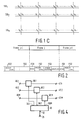
- the sub-band signals are combined in consecutive signal blocks of q consecutive samples, see Fig. 1c, and are applied to an associated quantizer Q 1 to Q M .
- a quantizer Q m the samples are quantized to form quantized samples with a number of bits n m which is smaller than 16.
- Fig. 1 shows how the left sub-band signals are applied to an associated quantizer Q m in signal blocks of q consecutive samples.
- the right sub-band signals are applied to an associated quantizer (not shown) in signal blocks of q consecutive samples.
- the signal blocks (groups) of q consecutive samples of the sub-band signal parts are quantized to a smaller number of bits. q is equal to, for example 12.
- the q samples in a signal block are first scaled. This scaling is effected in the block denoted by 10 by dividing the amplitudes of the q samples by the amplitude of the sample having the largest absolute value in the signal block.
- the quantized samples in the sub-bands SB 1 to SB M are subsequently presented at the outputs 4.1 to 4.M.
- the input terminal 1 is also coupled to an input of signal processing means 20.
- the signal processing means 20 perform a signal processing operation on the input signal in such a way that the desired additional effect, as described hereinbefore, is obtained. This may mean that the signal processing means 20 add, for example reverberation to the audio signal, so that during reproduction a listener is given the impression of being in a concert hall or a church.
- the signal processing means 20 may also perform a frequency correction on the input signal, or a compression or expansion of the dynamic range. Such signal processing operations are often used for jazz or disco music.
- the signal applied to the input terminal 1 may be an analog signal.
- the D/A conversion can only take place downstream of the processor 20.
- a second A/D converter is incorporated in the connection between the input terminal 1 and the input of the splitting means 2, and downstream of the branch to the signal processor 20.
- the signal processor 20 is now analog. It is alternatively possible for the A/D conversion to take place upstream of the signal processor 20, for example in the connection between the input terminal and the input of the splitting means 2 and upstream of the branch to the signal processor 20. In that case the processor 20 is digital.
- the signal processor 20 has a control signal input 21 to which a signal processing control signal is applied. Under the influence of the signal processing control signal which is indicative of the type of signal processing operation which can be performed on the input signal, the signal processor 20 processes the input signal in accordance with this type of signal processing operation. The signal thus processed is applied to the input of second splitting means 2' which are similar to the splitting means 2. Consequently, M sub-band signals obtained from the processed input signal appear at the outputs 22.1 to 22.M.
- the outputs 22.1 to 22.M are coupled to the inputs 5.1 to 5.M, respectively of means 6 for determining the need of bits.
- the means 6 for determining the need of bits determine the bit need b m for signal blocks, which correspond to one another with respect to time, of q samples of the sub-band signals of the processed signal in the sub-bands SB 1 to SB M .
- the bit need b m is a number which is in relation to the number of bits with which the q samples in a signal block of q samples in a sub-band signal of the processed signal would have to be quantized in the sub-band with the serial number of m.
- bit needs b 1 to b M derived by the means 6 for determining the need of bits, are applied to bit allocation means 7.
- the bit allocation means 7 determine the real number of bits n 1 to n M with which the q samples of the corresponding signal blocks in the sub-band signals obtained from the processed signal are quantized.
- Control signals corresponding to the numbers n 1 to n M are applied to the respective quantizers Q 1 to Q M via the leads 8.1 to 8.M.
- the special feature thus is that the signal which is not processed in the signal processor 20 is quantized on the basis of the bit allocation information n 1 to n M obtained from the signal processed by the signal processor 20.
- the quantized samples in the signal blocks of the sub-band signals are subsequently applied to inputs 4.1 to 4.M of a signal combination unit 14.
- the bit allocation information which is composed of the numbers n 1 to n M , is also applied after a possible conversion to inputs 12.1 to 12.M of the combination unit 14.
- Document (2) indicates that the numbers in the bit allocation information indicating the number of bits by which samples are represented are converted to y-bit code words in which y is equal to 4, see Fig. 9 in document (2).
- the scale factor information which is composed of the scale factors SF 1 to SF M , is also applied after a possible conversion to the inputs 11.1 to 11.M of the combination unit 14.
- Fig. 1B shows the second part of the transmitter which in addition to the combination unit 14 comprises a second coder 15 and means 16 for applying the signal presented at its input to a transmission medium.
- This transmission medium is a magnetic record carrier in this case.
- the samples, the bit allocation information and the scale factor information for the right signal parts in the sub-bands are of course also applied to the combination unit 14.
- the unit 14 combines the signals and accommodates them serially in consecutive frames of a second digital signal which is presented at its output.
- Fig. 2 shows the format of this second digital signal. This format is described extensively in publication (2) in the list of References.
- Fig. 2 shows the second digital signal with the consecutive frames j-1, j, j+1 and shows how a frame may be built up.
- the frame comprises a first frame part FD1 which may comprise synchronization information, a second frame part FD2 which comprises the allocation information and a third frame part FD3.
- This third frame part comprises the scale factor information first, followed by the samples of the quantized signals in the sub-bands.
- the second digital signal is applied to the input 18 of the second coder 15.
- the second digital signal is coded in such a way that an error correction of the received information is possible at the receiver end.
- a Reed Solomon coding and possibly an interleaving is performed on the second digital signal.
- the signal is further coded in such a way that the information to be transmitted is suitable for transmission via the transmission medium.
- an 8-to-10 conversion may be performed on the 8-bit words constituting the signal.
- Such an 8-to-10 conversion is described, for example in EP-A-150082 in the name of the Applicant. In this conversion the information words are converted from 8-bit code words to 10-bit code words.
- the third digital signal thus obtained is presented at the output 19.
- This output 19 is coupled to the input of means 16 which are formed as recording means 16 for recording the third digital signal on a magnetic record carrier.
- the control signal input 21 is preferably also coupled to an input 13 of the unit 14.
- the unit 14 is then also adapted to apply the signal processing control signal to the frames and to store information which is related to this control signal in a frame part of the frames, preferably in the first frame part FD1.
- Fig. 3 shows the first part of a second embodiment of the transmitter according to the invention. This part could be used instead of the part shown in Fig. 1a of the transmitter of Fig. 1.
- the part of Fig. 3 shows great resemblance to the part of Fig. 1a, with the difference that the signal processing means 20 and the second splitting means 2' have been omitted, while a correction unit 45 is added between the bit allocation means 7 and the leads 8.1 to 8.M to the quantizers Q 1 to Q M .
- the inputs 5.1 to 5.M are further coupled in known manner to the outputs 3.1 to 3.M of the splitting means 2.
- the device without the correction means 45 would code the input signal in known manner, and this in such a way that a possible additional signal processing at the receiver end would not be taken into account.
- the correction means 45 now correct the bit allocation information of the bit allocation means 7 in such a way that this signal processing operation at the receiver end is taken into account.
- the correction means may be formed in the way as is shown in Fig. 4.
- An input 46.m is coupled to an output 47.m via a combination unit 48. m.
- the control signal input 21 is coupled to an input 52 of a microprocessor 49.
- Outputs 50.1 to 50.M of the microprocessor 49 are coupled to second inputs of the combination units 48.1 to 48.M.
- the microprocessor 49 Under the influence of a control signal which is presented at the input 21, the microprocessor 49 generates correction values at one or more outputs 50.1 to 50.M, which values are applied to the combination units 48.1 to 48.M. Dependent on the type of control signal, and hence dependent on the type of signal processing operation performed on the audio information at the receiver end, other correction values are supplied from the outputs 50.1 to 50.M.
- the sets of correction values for the different control signals, hence for the different signal processing operations may be stored, for example in associated memory sites in the microprocessor 49 and are read from the associated memory sites when a control signal is applied.
- the correction values are, for example values (in numbers of bits per sample) which must be added to the values applied by the bit allocation means 7 to the inputs 46.1 to 46.M.
- Fig. 5 shows diagrammatically an embodiment of the receiver according to the invention.
- the receiver comprises means 30 for receiving the third digital signal from the transmission medium.
- the means 30 are formed as read means for reading the information from a magnetic record carrier.
- the third digital signal which has been read is applied to an input 31 of error correction means 32.
- error correction means 32 In the means 32 a 10-to-8 conversion is realised first. Subsequently, an error correction and a possible de-interleaving operation is performed on the information which has been read.
- the signal thus decoded corresponds again to the digital signal as is shown in Fig. 2.
- This signal is presented at an output 33.
- the means 35 derive the allocation information, the scale factor information and the samples for each signal block in each sub-band from the frames.
- the sub-band signals SB 1 to SB M then appear at the outputs 37.1 to 37.M.
- These subband signals are presented at inputs 39.1 to 39.M of synthesis filter means 36 which compose a replica of the wideband signal from the sub-band signals.
- the operation of these synthesis filter means 36 has been described extensively in publication (5) in the list of References.
- the replica of the wideband signal is presented at an input 56 of signal processing means 55 by means 36, possibly after D/A conversion.
- the signal thus processed is presented at an output 40 of the receiver. This is, for example the left signal part of the original signal. It is of course evident that the means 35 have M outputs at which the sub-band signals of the right signal part are available.
- Synthesis filter means (not shown) such as the filter means 36 are present to reconstruct the original right signal part from these sub-band signal parts.
- the means 35 possibly also derive the signal processing control signal from the frames and apply this control signal to an output 60 which is coupled to a control signal input 57 of the signal processing means 55.
- the operation of the signal processing means 55 is identical to the operation of the signal processing means 21 as described with reference to Fig. 1a.
- the output 60 may be further coupled to an input 58 of a display 59. Under the influence of the control signal applied to the display 59, the display shows which type of signal processing operation has been performed on the audio signal by the processing means 55.
- the greater part of the description of the invention refers to coding and transmission of a monosignal. However, the invention is not limited thereto.
- the invention is also applicable to coding a stereo signal in which two signal parts, viz . left and right are present in each sub-band.
- the invention is also applicable to coding devices in which one or more of the sub-band signals can be coded in a stereo intensity mode.
- the intensity mode coding reference is made to publications (2) and (4) in the list of References.
- the invention is not limited to a transmitter in which the splitting means split up the wideband signal into sub-bands, but that instead a transform coding may alternatively be employed in the splitting means.
Landscapes
- Engineering & Computer Science (AREA)
- Computer Networks & Wireless Communication (AREA)
- Signal Processing (AREA)
- Transmission Systems Not Characterized By The Medium Used For Transmission (AREA)
- Compression, Expansion, Code Conversion, And Decoders (AREA)
Claims (16)
- Emetteur pour un système de transmission numérique pour transmettre un signal à large bande par l'intermédiaire d'un support de transmission, lequel signal est échantillonné à une fréquence d'échantillonnage donnée Fs, par exemple un signal audio numérique, lequel émetteur comprend :une borne d'entrée (1) pour recevoir le signal à large bande ;des moyens de division de signal (2) pour produire, en réaction au signal à large bande, une pluralité de M sous-signaux à bande étroite à une fréquence d'échantillonnage diminuée, auxquelles fins les moyens de division divisent le signal à large bande en sous-bandes consécutives de numéros de bande m qui augmentent avec la fréquence, dans lesquels m se conforme à 1 ≤ m ≤ M, un sous-signal étant composé de blocs de signaux consécutifs, chaque bloc de signaux comprenant q échantillons ;des moyens d'attribution de bits (2', 6, 7) pour produire des informations d'attribution de bits indiquant la quantité de bits par laquelle les q échantillons d'un bloc de signaux sont représentés dans une sous-bande, et pour appliquer les informations d'attribution de bits à desmoyens de quantification (Q1, ..., QM) couplés aux moyens de division de signal (2) et propres à quantifier les M sous-signaux en blocs en réaction aux informations d'attribution de bits des moyens d'attribution de bits ;des moyens (14) pour loger les sous-signaux quantifiés et les informations d'attribution de bits dans une trame d'un deuxième signal numérique qui est composé de trames consécutives ;des moyens de codage (15) pour convertir le deuxième signal numérique en un troisième signal numérique de sorte qu'il soit approprié à une transmission par l'intermédiaire du support de transmission, etdes moyens (16) pour appliquer le troisième signal numérique au support de transmission, caractérisé en ce que l'émetteur comprend en outre :des moyens de traitement de signaux (20) comportant une entrée couplée à la borne d'entrée (1), une sortie et une entrée de signal de commande (21) ;des deuxièmes moyens de division de signal (2') comportant une entrée couplée à la sortie des moyens de traitement de signaux (20) pour produire, en réaction au signal numérique traité à partir des moyens de traitement de signaux, une pluralité de M sous-signaux à une fréquence d'échantillonnage diminuée, auxquelles fins les deuxièmes moyens de division divisent le signal à large bande traité en sous-bandes consécutives de numéros de bande m qui augmentent avec la fréquence, en ce que les moyens d'attribution de bits (6,7) sont couplés à la sortie des deuxièmes moyens de division (2') pour dériver les informations d'attribution de bits des sous-signaux, et en ce que les moyens de traitement de signaux (20) sont propres à traiter le signal à large bande en fonction d'un signal de commande de traitement de signaux qui est appliqué à l'entrée de signal de commande (21) des moyens de traitement de signaux (20).
- Emetteur pour un système de transmission numérique pour transmettre un signal à large bande par l'intermédiaire d'un support de transmission, lequel signal est échantillonné à une fréquence d'échantillonnage donnée Fs, par exemple un signal audio numérique, lequel émetteur comprend :une borne d'entrée (1) pour recevoir le signal à large bande ;des moyens de division de signal (2) pour produire, en réaction au signal à large bande, une pluralité de M sous-signaux à bande étroite à une fréquence d'échantillonnage diminuée, auxquelles fins les moyens de division divisent le signal à large bande en sous-bandes consécutives de numéros de bande m qui augmentent avec la fréquence, dans lesquels m se conforme à 1 ≤ m ≤ M, un sous-signal étant composé de blocs de signaux consécutifs, chaque bloc de signaux comprenant q échantillons ;des moyens d'attribution de bits (2, 6, 7) pour produire des informations d'attribution de bits indiquant la quantité de bits par laquelle les q échantillons d'un bloc de signaux sont représentés dans une sous-bande, et pour appliquer les informations d'attribution de bits à desmoyens de quantification (Q1, ..., QM) couplés aux moyens de division de signal (2) et propres à quantifier les M sous-signaux en blocs en réaction aux informations d'attribution de bits des moyens d'attribution de bits ;des moyens (14) pour loger les sous-signaux quantifiés et les informations d'attribution de bits dans une trame d'un deuxième signal numérique qui est composé de trames consécutives ;des moyens de codage (15) pour convertir le deuxième signal numérique en un troisième signal numérique de sorte qu'il soit approprié à une transmission par l'intermédiaire du support de transmission, etdes moyens (16) pour appliquer le troisième signal numérique au support de transmission, caractérisé en ce que l'émetteur comprend en outre :des moyens de correction (45) couplés aux moyens d'attribution de bits (2, 6, 7) et aux moyens de quantification, lesquels moyens de correction présentent une entrée de signal de commande (21), lesdits moyens de correction étant propres à corriger les informations d'attribution de bits des moyens d'attribution de bits en fonction d'un signal de commande de traitement de signaux qui est appliqué à l'entrée de signal de commande (21) des moyens de correction (45) et à appliquer les informations d'attribution de bits corrigées aux moyens de quantification.
- Emetteur suivant la revendication 1 ou 2, caractérisé en ce que l'émetteur comprend en outre des moyens (13, 14) pour appliquer le signal de commande de traitement de signaux au support de transmission.
- Emetteur suivant la revendication 1, 2 ou 3, caractérisé en ce que le signal de commande de traitement de signaux est lié à l'opération de traitement de signaux réalisée sur le signal à large bande d'une manière telle qu'un effet acoustique spatial est réalisé dans le signal à large bande traité.
- Emetteur suivant l'une quelconque des revendications précédentes, caractérisé en ce que l'émetteur se présente sous la forme d'un dispositif pour enregistrer le troisième signal numérique sur un support d'enregistrement.
- Emetteur suivant la revendication 5, caractérisé en ce que le support d'enregistrement est un support d'enregistrement magnétique.
- Récepteur pour recevoir un signal d'information numérique à large bande transmis par l'intermédiaire d'un support de transmission sous la forme d'un signal de transmission, le récepteur comprenant :caractérisé en ce que les moyens de dérivation (35) sont en outre propres à dériver un signal de commande de traitement de signaux des informations reçues du support de transmission, en ce que le récepteur comprend en outre des moyens de traitement de signaux (55) pour réaliser une opération de traitement de signaux sur le signal appliqué à une entrée (56) afin de produire un signal de sortie à la borne de sortie (40) qui est une version traitée dudit signal d'information numérique à large bande, lesdits moyens de traitement de signaux comportant une entrée de signal de commande (57) qui est couplée à une sortie (60) des moyens de dérivation (35), et en ce que les moyens de traitement de signaux (55) sont propres à réaliser l'opération de traitement de signaux en fonction du signal de commande de traitement de signaux appliqué à l'entrée de signal de commande (57).des moyens de lecture (30) pour recevoir le signal de transmission depuis le support de transmission ;des moyens de décodage (32) pour convertir le signal de transmission en un signal de transmission décodé ;des moyens de dérivation (35) pour dériver des sous-signaux quantifiés et des informations d'attribution de bits à partir de trames incluses dans le signal de transmission décodé;des moyens de filtre de synthèse (36) pour construire, en réaction aux sous-signaux quantifiés, une réplique du signal à large bande, lesdits moyens de filtre de synthèse combinant les sous-bandes à une fréquence d'échantillonnage augmentée à la bande de signal du signal d'information à large bande ;une borne de sortie (40) pour fournir un signal de sortie,
- Récepteur suivant la revendication 7, caractérisé en ce que les moyens de traitement de signaux (55) sont propres à réaliser une opération de traitement de signaux de manière telle qu'un effet acoustique spatial est réalisé dans le signal d'information numérique à large bande traité.
- Récepteur suivant la revendication 7 ou 8, caractérisé en ce que le récepteur se présente sous la forme d'un dispositif pour lire le signal de transmission depuis un support d'enregistrement.
- Récepteur suivant la revendication 9, caractérisé en ce que le support d'enregistrement est un support d'enregistrement magnétique.
- Récepteur suivant la revendication 7, 8, 9 ou 10, caractérisé en ce que le récepteur comprend un affichage (59) comportant une entrée de signal de commande (58) qui est couplée à la sortie (60) des moyens de dérivation (35) et en ce que l'affichage est propre à indiquer, en fonction du signal de commande de traitement de signaux présenté à l'entrée de signal de commande, le type d'effet acoustique spatial réalisé par les moyens de traitement de signaux.
- Appareil pour coder un signal à large bande échantillonné à une fréquence d'échantillonnage donnée Fs, par exemple un signal audio numérique, l'appareil comprenant :une borne d'entrée (1) pour recevoir le signal à large bande ;des moyens de division de signal (2) pour produire, en réaction au signal à large bande, une pluralité de M sous-signaux à bande étroite à une fréquence d'échantillonnage diminuée, auxquelles fins les moyens de division divisent le signal à large bande en sous-bandes consécutives de numéros de bande m qui augmentent avec la fréquence, dans lesquels m se conforme à 1 ≤ m ≤ M, un sous-signal étant composé de blocs de signaux consécutifs, chaque bloc de signaux comprenant q échantillons ;des moyens d'attribution de bits (2', 6, 7) pour produire des informations d'attribution de bits indiquant la quantité de bits par laquelle les q échantillons d'un bloc de signaux sont représentés dans une sous-bande, et pour appliquer les informations d'attribution de bits à desmoyens de quantification (Q1, ..., QM) couplés aux moyens de division de signal (2) et propres à quantifier les M sous-signaux en blocs en réaction aux informations d'attribution de bits des moyens d'attribution de bits, caractérisé en ce que l'appareil comprend en outre :des moyens de traitement de signaux (20) comportant une entrée couplée à la borne d'entrée (1), une sortie et une entrée de signal de commande (21) ;des deuxièmes moyens de division de signal (2') comportant une entrée couplée à la sortie des moyens de traitement de signaux (20) pour produire, en réaction au signal numérique traité des moyens de traitement de signaux, une pluralité de M sous-signaux à une fréquence d'échantillonnage diminuée, auxquelles fins les deuxièmes moyens de division divisent le signal à large bande traité en sous-bandes consécutives de numéros de bandes m qui augmentent avec la fréquence, en ce que les moyens d'attribution de bits (6,7) sont couplés à la sortie des deuxièmes moyens de division (2') pour dériver les informations d'attribution de bits des sous-signaux, en ce que les moyens de traitement de signaux (20) sont propres à traiter le signal à large bande en fonction d'un signal de commande de traitement de signaux qui est appliqué à l'entrée de signal de commande (21) des moyens de traitement de signaux (20).
- Appareil pour coder un signal à large bande échantillonné à une fréquence d'échantillonnage donnée Fs, par exemple un signal audio numérique, l'appareil comprenant :caractérisé en ce que l'appareil comprend en outre :une borne d'entrée (1) pour recevoir le signal à large bande ;des moyens de division de signal (2) pour produire, en réaction au signal à large bande, une pluralité de M sous-signaux à bande étroite à une fréquence d'échantillonnage diminuée, auxquelles fins les moyens de division divisent le signal à large bande en sous-bandes consécutives de numéros de bande m qui augmentent avec la fréquence, dans lesquels m se conforme à 1 ≤ m ≤ M, un sous-signal étant composé de blocs de signaux consécutifs, chaque bloc de signaux comprenant q échantillons ;des moyens d'attribution de bits (2, 6, 7) pour produire des informations d'attribution de bits indiquant la quantité de bits par laquelle les q échantillons d'un bloc de signaux sont représentés dans une sous-bande, et pour appliquer les informations d'attribution de bits à desmoyens de quantification (Q1, ..., QM) couplés aux moyens de division de signal (2) et propres à quantifier les M sous-signaux en blocs en réaction aux informations d'attribution de bits des moyens d'attribution de bits,des moyens de correction (45) couplés aux moyens d'attribution de bits (2, 6, 7) et aux moyens de quantification, lesquels moyens de correction présentent une entrée de signal de commande (21), lesdits moyens de correction étant propres à corriger les informations d'attribution de bits des moyens d'attribution de bits en fonction d'un signal de commande de traitement de signaux qui est appliqué à l'entrée de signal de commande (21) des moyens de correction (45) et à appliquer les informations d'attribution de bits corrigées aux moyens de quantification.
- Appareil pour décoder un signal d'information numérique à large bande codé en un signal d'information codé, l'appareil comprenant :caractérisé en ce que les moyens de dérivation sont en outre propres à dériver un signal de commande de traitement de signaux du signal d'information codé, en ce que l'appareil comprend en outre des moyens de traitement de signaux (55) pour réaliser une opération de traitement de signaux sur le signal appliqué à une entrée afin de produire un signal de sortie à la borne de sortie (40) qui est une version traitée dudit signal d'information numérique à large bande, lesdits moyens de traitement de signaux comportant une entrée de signal de commande (57) qui est couplée à une sortie (60) des moyens de dérivation (35), et en ce que les moyens de traitement de signaux (55) sont propres à réaliser l'opération de traitement de signaux en fonction du signal de commande de traitement de signaux appliqué à l'entrée de signal de commande (57).des moyens de dérivation (35) pour dériver des sous-signaux quantifiés et des informations d'attribution de bits à partir de trames incluses dans le signal d'information codé;des moyens de filtre de synthèse (36) pour construire, en réaction aux sous-signaux quantifiés, une réplique du signal à large bande, lesdits moyens de filtre de synthèse combinant les sous-bandes à une fréquence d'échantillonnage augmentée à la bande de signal du signal d'information à large bande ;une borne de sortie (40) pour fournir un signal de sortie,
- Procédé de transmission d'un signal à large bande par l'intermédiaire d'un support de transmission, lequel signal est échantillonné à une fréquence d'échantillonnage donnée Fs, par exemple un signal audio numérique, le procédé comprenant les étapes suivantes :caractérisé en ce que le procédé comprend en outre les étapes suivantes :recevoir le signal à large bande ;produire, en réaction au signal à large bande, une pluralité de M sous-signaux à bande étroite à une fréquence d'échantillonnage diminuée, en divisant le signal à large bande en sous-bandes consécutives de numéros de bande m qui augmentent avec la fréquence, dans lesquels m se conforme à 1 ≤ m ≤ M, un sous-signal étant composé de blocs de signaux consécutifs, chaque bloc de signaux comprenant q échantillons ;produire des informations d'attribution de bits indiquant la quantité de bits par laquelle les q échantillons d'un bloc de signaux sont représentés dans une sous-bande,quantifier les M sous-signaux en blocs en réaction aux informations d'attribution de bits ;loger les sous-signaux quantifiés et les informations d'attribution de bits dans une trame d'un deuxième signal numérique qui est composé de trames consécutives ;convertir le deuxième signal numérique en un troisième signal numérique de sorte qu'il soit approprié à une transmission par l'intermédiaire du support de transmission, etappliquer le troisième signal numérique au support de transmission,appliquer un signal de commande de traitement de signaux ;soumettre à un traitement de signaux le signal à large bande en fonction du signal de commande de traitement de signaux ;produire, en réaction au signal à large bande traité, une pluralité de M sous-signaux à bande étroite à une fréquence d'échantillonnage diminuée, en divisant le signal à large bande traité en sous-bandes consécutives de numéros de bande m qui augmentent avec la fréquence, etdériver les informations d'attribution de bits à partir du signal à large bande traité divisé.
- Procédé de transmission d'un signal à large bande par l'intermédiaire d'un support de transmission, lequel signal est échantillonné à une fréquence d'échantillonnage donnée Fs, par exemple un signal audio numérique, le procédé comprenant les étapes suivantes :caractérisé en ce que le procédé comprend en outre les étapes suivantes :recevoir le signal à large bande ;produire, en réaction au signal à large bande, une pluralité de M sous-signaux à bande étroite à une fréquence d'échantillonnage diminuée, en divisant le signal à large bande en sous-bandes consécutives de numéros de bande m qui augmentent avec la fréquence, dans lesquels m se conforme à 1 ≤ m ≤ M, un sous-signal étant composé de blocs de signaux consécutifs, chaque bloc de signaux comprenant q échantillons ;produire des informations d'attribution de bits indiquant la quantité de bits par laquelle les q échantillons d'un bloc de signaux sont représentés dans une sous-bande,quantifier les M sous-signaux en blocs en réaction aux informations d'attribution de bits ;loger les sous-signaux quantifiés et les informations d'attribution de bits dans une trame d'un deuxième signal numérique qui est composé de trames consécutives ;convertir le deuxième signal numérique en un troisième signal numérique de sorte qu'il soit approprié à une transmission par l'intermédiaire du support de transmission, etappliquer le troisième signal numérique au support de transmission,appliquer un signal de commande de traitement de signaux ;corriger les informations d'attribution de bits dérivées de l'étape de production d'attribution de bits en fonction du signal de commande de traitement de signaux ;quantifier les sous-signaux en réaction aux informations d'attribution de bits.
Priority Applications (1)
| Application Number | Priority Date | Filing Date | Title |
|---|---|---|---|
| EP19930201506 EP0573103B1 (fr) | 1992-06-02 | 1993-05-26 | Système de transmission numérique |
Applications Claiming Priority (3)
| Application Number | Priority Date | Filing Date | Title |
|---|---|---|---|
| EP92201579 | 1992-06-02 | ||
| EP92201579 | 1992-06-02 | ||
| EP19930201506 EP0573103B1 (fr) | 1992-06-02 | 1993-05-26 | Système de transmission numérique |
Publications (2)
| Publication Number | Publication Date |
|---|---|
| EP0573103A1 EP0573103A1 (fr) | 1993-12-08 |
| EP0573103B1 true EP0573103B1 (fr) | 1999-08-11 |
Family
ID=26131431
Family Applications (1)
| Application Number | Title | Priority Date | Filing Date |
|---|---|---|---|
| EP19930201506 Expired - Lifetime EP0573103B1 (fr) | 1992-06-02 | 1993-05-26 | Système de transmission numérique |
Country Status (1)
| Country | Link |
|---|---|
| EP (1) | EP0573103B1 (fr) |
Families Citing this family (1)
| Publication number | Priority date | Publication date | Assignee | Title |
|---|---|---|---|---|
| EP1271819A3 (fr) * | 1993-10-27 | 2004-01-21 | Koninklijke Philips Electronics N.V. | Transmission et réception d' une première et une deuxième composantes principales de signal |
Family Cites Families (2)
| Publication number | Priority date | Publication date | Assignee | Title |
|---|---|---|---|---|
| JPH03219800A (ja) * | 1990-01-24 | 1991-09-27 | Toshiba Corp | 音響効果装置 |
| NL9001128A (nl) * | 1990-05-14 | 1991-12-02 | Philips Nv | Kodeerinrichting bevattende een subbandkoder, en een zender voorzien van de kodeerinrichting. |
-
1993
- 1993-05-26 EP EP19930201506 patent/EP0573103B1/fr not_active Expired - Lifetime
Also Published As
| Publication number | Publication date |
|---|---|
| EP0573103A1 (fr) | 1993-12-08 |
Similar Documents
| Publication | Publication Date | Title |
|---|---|---|
| AU2020204222B2 (en) | Method and apparatus for generating from a coefficient domain representation of HOA signals a mixed spatial/coefficient domain representation of said HOA signals | |
| KR100279094B1 (ko) | 디지털신호부호화장치 | |
| JP3178026B2 (ja) | ディジタル信号符号化装置及び復号化装置 | |
| KR100299528B1 (ko) | 인텐서티-스테레오 프로세스와 예측 프로세스를 이용한 오디오신호의 부호화/복호화 장치 및 그 방법 | |
| JP3278900B2 (ja) | データ符号化装置及び方法 | |
| EP0714173B1 (fr) | Procede et dispositif de codage de signal, procede et dispositif de decodage de signal, support d'enregistrement et procede de transmission de signaux | |
| GB2340351A (en) | Inserting auxiliary data for use during subsequent coding | |
| KR100512208B1 (ko) | 디지탈신호처리방법,디지탈신호처리장치,디지탈신호기록방법,디지탈신호기록장치,기록매체,디지탈신호전송방법,및디지탈신호전송장치 | |
| JPWO1995034956A1 (ja) | 信号符号化方法及び装置、信号復号化方法及び装置、記録媒体、並びに信号伝送装置 | |
| US5440596A (en) | Transmitter, receiver and record carrier in a digital transmission system | |
| JP3250376B2 (ja) | 情報符号化方法及び装置並びに情報復号化方法及び装置 | |
| US5781586A (en) | Method and apparatus for encoding the information, method and apparatus for decoding the information and information recording medium | |
| JP3277699B2 (ja) | 信号符号化方法及び装置並びに信号復号化方法及び装置 | |
| US6353584B1 (en) | Reproducing and recording apparatus, decoding apparatus, recording apparatus, reproducing and recording method, decoding method and recording method | |
| EP0775389B1 (fr) | Systeme et procede de codage visant a coder un signal numerique possedant au moins un premier et un second composant | |
| JP3193437B2 (ja) | 伝送システム及び伝送システムに使用される受信機 | |
| US5899966A (en) | Speech decoding method and apparatus to control the reproduction speed by changing the number of transform coefficients | |
| JP3993229B2 (ja) | 第1および第2主信号成分の送信および受信 | |
| WO1994018762A1 (fr) | Transmission de mots contenant des donnees numeriques representant une forme d'onde de signal | |
| EP0573103B1 (fr) | Système de transmission numérique | |
| JP3336619B2 (ja) | 信号処理装置 | |
| US6574602B1 (en) | Dual channel phase flag determination for coupling bands in a transform coder for high quality audio | |
| JPH09102742A (ja) | 符号化方法および装置、復号化方法および装置、並びに記録媒体 | |
| KR100675392B1 (ko) | 디지탈 정보신호를 송수신하는 송/수신 장치 및 방법 | |
| JP3827720B2 (ja) | 差分コーディング原理を用いる送信システム |
Legal Events
| Date | Code | Title | Description |
|---|---|---|---|
| PUAI | Public reference made under article 153(3) epc to a published international application that has entered the european phase |
Free format text: ORIGINAL CODE: 0009012 |
|
| AK | Designated contracting states |
Kind code of ref document: A1 Designated state(s): AT BE DE FR GB |
|
| 17P | Request for examination filed |
Effective date: 19940530 |
|
| 17Q | First examination report despatched |
Effective date: 19970307 |
|
| GRAG | Despatch of communication of intention to grant |
Free format text: ORIGINAL CODE: EPIDOS AGRA |
|
| RAP3 | Party data changed (applicant data changed or rights of an application transferred) |
Owner name: KONINKLIJKE PHILIPS ELECTRONICS N.V. |
|
| GRAG | Despatch of communication of intention to grant |
Free format text: ORIGINAL CODE: EPIDOS AGRA |
|
| GRAH | Despatch of communication of intention to grant a patent |
Free format text: ORIGINAL CODE: EPIDOS IGRA |
|
| GRAH | Despatch of communication of intention to grant a patent |
Free format text: ORIGINAL CODE: EPIDOS IGRA |
|
| GRAA | (expected) grant |
Free format text: ORIGINAL CODE: 0009210 |
|
| AK | Designated contracting states |
Kind code of ref document: B1 Designated state(s): AT BE DE FR GB |
|
| PG25 | Lapsed in a contracting state [announced via postgrant information from national office to epo] |
Ref country code: BE Free format text: LAPSE BECAUSE OF FAILURE TO SUBMIT A TRANSLATION OF THE DESCRIPTION OR TO PAY THE FEE WITHIN THE PRESCRIBED TIME-LIMIT Effective date: 19990811 Ref country code: AT Free format text: LAPSE BECAUSE OF FAILURE TO SUBMIT A TRANSLATION OF THE DESCRIPTION OR TO PAY THE FEE WITHIN THE PRESCRIBED TIME-LIMIT Effective date: 19990811 |
|
| REF | Corresponds to: |
Ref document number: 183345 Country of ref document: AT Date of ref document: 19990815 Kind code of ref document: T |
|
| REF | Corresponds to: |
Ref document number: 69325950 Country of ref document: DE Date of ref document: 19990916 |
|
| ET | Fr: translation filed | ||
| PLBE | No opposition filed within time limit |
Free format text: ORIGINAL CODE: 0009261 |
|
| STAA | Information on the status of an ep patent application or granted ep patent |
Free format text: STATUS: NO OPPOSITION FILED WITHIN TIME LIMIT |
|
| 26N | No opposition filed | ||
| REG | Reference to a national code |
Ref country code: GB Ref legal event code: IF02 |
|
| PGFP | Annual fee paid to national office [announced via postgrant information from national office to epo] |
Ref country code: DE Payment date: 20040714 Year of fee payment: 12 |
|
| PGFP | Annual fee paid to national office [announced via postgrant information from national office to epo] |
Ref country code: GB Payment date: 20050518 Year of fee payment: 13 |
|
| PGFP | Annual fee paid to national office [announced via postgrant information from national office to epo] |
Ref country code: FR Payment date: 20050527 Year of fee payment: 13 |
|
| PG25 | Lapsed in a contracting state [announced via postgrant information from national office to epo] |
Ref country code: DE Free format text: LAPSE BECAUSE OF NON-PAYMENT OF DUE FEES Effective date: 20051201 |
|
| PG25 | Lapsed in a contracting state [announced via postgrant information from national office to epo] |
Ref country code: GB Free format text: LAPSE BECAUSE OF NON-PAYMENT OF DUE FEES Effective date: 20060526 |
|
| GBPC | Gb: european patent ceased through non-payment of renewal fee |
Effective date: 20060526 |
|
| REG | Reference to a national code |
Ref country code: FR Ref legal event code: ST Effective date: 20070131 |
|
| PG25 | Lapsed in a contracting state [announced via postgrant information from national office to epo] |
Ref country code: FR Free format text: LAPSE BECAUSE OF NON-PAYMENT OF DUE FEES Effective date: 20060531 |