EP0573246A2 - Magnetische Aufzeichnungs-/Wiedergabevorrichtung zum Aufzeichnen/Wiedergeben eines Videosignals und eines hinzugefügten Hilfssignals - Google Patents
Magnetische Aufzeichnungs-/Wiedergabevorrichtung zum Aufzeichnen/Wiedergeben eines Videosignals und eines hinzugefügten Hilfssignals Download PDFInfo
- Publication number
- EP0573246A2 EP0573246A2 EP93304228A EP93304228A EP0573246A2 EP 0573246 A2 EP0573246 A2 EP 0573246A2 EP 93304228 A EP93304228 A EP 93304228A EP 93304228 A EP93304228 A EP 93304228A EP 0573246 A2 EP0573246 A2 EP 0573246A2
- Authority
- EP
- European Patent Office
- Prior art keywords
- signal
- circuit
- recording
- output
- magnetic
- Prior art date
- Legal status (The legal status is an assumption and is not a legal conclusion. Google has not performed a legal analysis and makes no representation as to the accuracy of the status listed.)
- Withdrawn
Links
Images


Classifications
-
- H—ELECTRICITY
- H04—ELECTRIC COMMUNICATION TECHNIQUE
- H04N—PICTORIAL COMMUNICATION, e.g. TELEVISION
- H04N5/00—Details of television systems
- H04N5/76—Television signal recording
- H04N5/78—Television signal recording using magnetic recording
- H04N5/782—Television signal recording using magnetic recording on tape
- H04N5/78213—Television signal recording using magnetic recording on tape involving recording in different depths of the magnetic tape
-
- H—ELECTRICITY
- H04—ELECTRIC COMMUNICATION TECHNIQUE
- H04N—PICTORIAL COMMUNICATION, e.g. TELEVISION
- H04N9/00—Details of colour television systems
- H04N9/79—Processing of colour television signals in connection with recording
- H04N9/797—Processing of colour television signals in connection with recording for recording the signal in a plurality of channels, the bandwidth of each channel being less than the bandwidth of the signal
- H04N9/7973—Processing of colour television signals in connection with recording for recording the signal in a plurality of channels, the bandwidth of each channel being less than the bandwidth of the signal by dividing the luminance or colour component signal samples or frequency bands among a plurality of recording channels
-
- H—ELECTRICITY
- H04—ELECTRIC COMMUNICATION TECHNIQUE
- H04N—PICTORIAL COMMUNICATION, e.g. TELEVISION
- H04N9/00—Details of colour television systems
- H04N9/79—Processing of colour television signals in connection with recording
- H04N9/80—Transformation of the television signal for recording, e.g. modulation, frequency changing; Inverse transformation for playback
- H04N9/82—Transformation of the television signal for recording, e.g. modulation, frequency changing; Inverse transformation for playback the individual colour picture signal components being recorded simultaneously only
- H04N9/83—Transformation of the television signal for recording, e.g. modulation, frequency changing; Inverse transformation for playback the individual colour picture signal components being recorded simultaneously only the recorded chrominance signal occupying a frequency band under the frequency band of the recorded brightness signal
- H04N9/832—Transformation of the television signal for recording, e.g. modulation, frequency changing; Inverse transformation for playback the individual colour picture signal components being recorded simultaneously only the recorded chrominance signal occupying a frequency band under the frequency band of the recorded brightness signal using an increased bandwidth for the luminance or the chrominance signal
-
- H—ELECTRICITY
- H04—ELECTRIC COMMUNICATION TECHNIQUE
- H04N—PICTORIAL COMMUNICATION, e.g. TELEVISION
- H04N5/00—Details of television systems
- H04N5/76—Television signal recording
- H04N5/78—Television signal recording using magnetic recording
- H04N5/782—Television signal recording using magnetic recording on tape
- H04N5/7824—Television signal recording using magnetic recording on tape with rotating magnetic heads
- H04N5/7826—Television signal recording using magnetic recording on tape with rotating magnetic heads involving helical scanning of the magnetic tape
- H04N5/78263—Television signal recording using magnetic recording on tape with rotating magnetic heads involving helical scanning of the magnetic tape for recording on tracks inclined relative to the direction of movement of the tape
Definitions
- the present invention relates to a video taperecorder (referred to as a VCR hereinafter) for recording and reproducing a color video signal of PAL, SECAM, or High-definition television system.
- a video taperecorder referred to as a VCR hereinafter
- VCRs A variety of home VCRs are widely used for recording and reproducing a color video signal of VHS or 8-mm format. Particularly, the VCRs of VHS format now prevail over 250 million units throughout the world, becoming a must item in every home.
- the VCR separates an input PAL or SECAM color video signal into a luminance component and a chrominance carrier component.
- the luminance signal is frequency modulated using a lowband carrier and the chrominance carrier signal is lowband converted before recorded onto a magnetic tape.
- Such recording/reproducing methods are depicted in, for example, Yokoyama's "Home video techniques" published by NHK(the Japanese Broadcasting Corporation) and Sugetani's study in "SMPTE Journal", March 1986, pp.301 to 309.
- Such conventional VCRs are however incapable of recording a combination video signal, e.g. PALplus, containing a PAL or SECAM video information and a helper (a vertical highband component of the luminance signal) in the foregoing manner.
- the helper signal of the PALplus signal is modulated with a color subcarrier and will thus be recorded with effects of color-under by a conventional VCR suffering a reduction in the bandwidth.
- the present invention allows an helper signal (or an augmentation signal) separated from the PALplus signal to be frequency modulated or digitized for overlap recording onto a part or all of the recording track where a conventional color video signal is stored. Also, two discrete output terminals are provided for delivering a PALplus composite reproduction signal and a PAL or SECAM video reproduction signal respectively. Accordingly, the VCR of the present invention becomes compatible with any conventional VCR.
- the PALplus signal can be recorded with its helper component separately of the PAL or SECAM components.
- a magnetic recording tape carrying the signals recorded by the VCR of the present invention will thus be reproduced by a conventional VCR for reproduction of the PAL or SECAM components.
- the helper signal will appear as two, upper and lower, black portions of the screen.
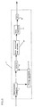
- Fig. 1 is a block diagram showing a primary part of the first embodiment. As shown, there is provided a second input terminal 100 to which a second color video or PALplus signal is introduced.
- the PALplus signal is divided into a helper signal and the other components by the action of a controller 101 and a selector switch 102. This will be explained in more detail referring to Fig. 7.
- Fig. 7 illustrates a screen image created by the video signal of the first embodiment in which the hatching areas represent the helper signal timebase multiplexed in the vertical period.
- This switching action of the selector switch 102 is controlled by a controller 101 which may contain a ROM.
- the helper signal is fed to the contact 108 while the other components are supplied to the contact 106.
- a composite video signal of the PAl or SECAM system is fed through a first input terminal 1 to a Y/C separator circuit 2 where it is divided into a luminance signal Y and a carrier chrominance signal C.
- the luminance signal Y from the Y/C separator circuit 2 is linearly or nonlinearly emphasized by an emphasizer circuit 5 and then, frequency modulated by an FM modulator circuit 6.
- the carrier chrominance signal C from the Y/C separator circuit 2 is transmitted to a lowband converter circuit 7 where its frequency is converted to a lower frequency than that of the frequency modulated luminance signal Y.
- the output of the lowband converter circuit 7 is then added by an adder circuit 8 to the frequency modulated luminance signal Y and a resultant sum signal is transferred to a recording amplifier 9.
- the helper signal of the PALplus input fed from the selector switch 102 to the contact 108 is demodulated and converted to a baseband helper signal by a demodulator circuit (DEMOD) 104, and is then sent to a digital recording signal processor circuit 12.
- the baseband helper signal is digitized and encoded to a digital modulation code form which is then fed to a recording amplifier 14.
- the arrangement of the digital recording signal processor circuit 12 will be explained in more detail referring to Fig. 5. As shown, there are provided an analog-to-digital converter 51, a data compressing circuit 52, an error correcting code encoding circuit 53, and a recording code encoding circuit 54.
- the signal from the demodulator circuit 104 is converted by the analog-to-digital (A/D) converter 51 to its digital signal.
- the digital signal of the analog-to-digital converter 51 is fed to the data compressing circuit 52 where its information is compressed by e.g. DCT or DPCM compression-technique.
- the DCT and DPCM compression techniques are well known and their details will be acquired from "Systematic image encoding" supervised by Miyahara, published IPC in 1990, or other literature.
- the output of the data compressing circuit 52 is fed to the error correcting code encoding circuit 53 for addition of an error correcting parity symbol such as a Reed-Solomon product code.
- the error correcting codes including the Reed-Solomon product code are explained in more details in e.g.
- the output of the error correcting code encoding circuit 53 is encoded by the recording code encoding circuit 54 to a modulation code of carrier signal, e.g. QPSK, which is then transferred to the recording amplifier 14.
- a modulation code of carrier signal e.g. QPSK
- the modulation codes of carrier signal including QPSK are described in details in e.g. "Digital micro-wave communications" written by Kuwabara, published by Kikaku Center in 1984.
- Fig. 1 also illustrates a rotary cylinder 15, of which rotating direction is denoted by 16, a magnetic tape 17, of which running direction is denoted by 18, and four magnetic heads 19,20,21,22 which are different in the azimuth angle.
- the magnetic tape 17 is wound on the rotary cylinder 15 through 180 degrees.
- the four magnetic heads 19,20,21,22 are helical-scan VCR transducers for helical scanning the magnetic tape 17.
- the output of the recording amplifier 9 is distributed through a known rotary transformer to the two heads 19 and 20 which are distanced about 180 degrees from each other on the circumference of the rotary cylinder 15 and recorded on a first recording track of the magnetic tape 17.
- the output of the recording amplifier 14 is distributed through a known rotary transformer to the two heads 21 and 22 which are distanced about 180 degrees from each other on the circumference of the rotary cylinder 15 and recorded on a second recording track of the magnetic tape 17.
- the output of the recording amplifier 9 is set to be at a particular or saturated recording level such that the recording currents of the heads 19,20 can allow a maximum of the output to be reproduced from the magnetic tape.
- the output of the recording amplifier 14 is set to be a lower or unsaturated recording level than said maximum level which permits the recording currents of the heads 21,22 to produce substantially a peak of the reproduction from the magnetic tape. Since the level of the second recording signals of the two heads 21,22, the second recording signals will hardly affect and interrupt the first recording signal on the magnetic tape when overlapping it during the recording. Accordingly, the second signal can be recorded without erasing most of the first signals stored on the magnetic tape.
- the first embodiment of the present invention allows the helper signal of the PALplus signal to be recorded and reproduced while the recording and reproduction of the conventional frequency modulated luminance signal and the lowband converted chrominance signal being carried out at the same station.
- Fig. 2 shows a pattern of the recording tracks.
- the two magnetic heads 19 and 21 are arranged at the azimuth angles of +6° and -15° respectively.
- the magnetic heads 20 and 22 are mounted at the azimuth angles of -6° and +15° respectively. Any two opposite heads arranged 180 degrees apart on the cylinder 15 have reverse azimuth angles to each other.
- Tl(+6) and T1(-6) are recording tracks scanned by their respective heads 19 and 20.
- T2(+15) and T2(-15) represent recorded tracks scanned by their respective heads 22 and 21.
- the track width is 19.3 ⁇ m for T1(+6) and T1(-6) and 10 ⁇ m for T2(+15) and T2(-15).
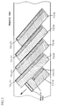
- Fig. 3 is a cross sectional view of the magnetic recording tape in which shown are a magnetic layer 40, a signal recording layer 41, a signal not-recording layer 42, a base film 43, and a back coating 44.
- the recording tracks are denoted T1(+6) by 45, T2(-15) by 46, T1(-6) by 47, and T2(+15) by 48. Since the level of recorded signals stored in T2(+15) and T2(-15) is low, recording tracks are in a shallow and near-surface area of the magnetic recording tape.
- Figs. 4(a) and 4(b) show frequency spectrums according to the first embodiment of the present invention.
- Fig. 4(a) illustrates the spectrum of a frequency band of the present invention for use with a conventional VHS-format VCR, in which the FM luminance signal has a frequency bandwidth between 1 MHz and 6 MHz substantially and does not extends over 6 MHz.
- the helper signal of the PALplus signal is recorded and reproduced between 6 MHz and 12 MHz.
- the C/N ratio of a playback carrier should be about 35 dB (at a noise frequency band of 30 kHz).
- the applicants found through various experiments that the C/N ratio of a digital chrominance signal when recording onto an S-VHS recording tape was measured more than 35 dB while the conventional VHS signal declined less than 1 dB in the C/N ratio. If the reproduction signal drops 2 dB, the noise level is attenuated in proportion and thus, a decrease in the C/N ratio will be a half or 1 dB. Also, if the PALplus helper signal overlaps the FM luminance signal in the frequency band, an azimuth loss between the recording tracks will eliminate the interference of crosstalk. Although the bandwidth of the PALplus signal in the first embodiment is between 6 MHz and 12 MHz, the effect of azimuth loss will allow both the FM luminance signal and the PALplus helper signal to share a specific range of 2 MHz to 4 MHz.
- Fig. 4(b) illustrates the spectrum of a frequency band of an S-VHS signal in a VCR, similar to that of the VHS signal.
- the bandwidth of the FM luminance signal extends from 1 MHz to 10 MHz leaving free the frequency range of over 10 MHz.
- the PALplus helper signal is assigned to a higher range of 10 MHz to 14 MHz.
- the bandwidth of the helper signal may however be allocated to a range from 2 MHz to 5 MHz or from 6 MHz to 12 MHz identical to that for the VHS signal with equal success where the FM luminance signal can share with the PALplus helper signal because of the effect of azimuth loss.
- the outputs of the two magnetic heads 19 and 20 are fed through the rotary transformer to a reproducing head amplifier 23 for amplification.
- the outputs of the other two heads 21,22 are transferred through the rotary transformer to a reproducing head amplifier 29 for amplification.
- the output of the reproducing amplifier 23 is fed to a bandpass filter (BPF) 24 where the FM luminance signal is extracted.
- BPF bandpass filter
- the FM luminance signal is then demodulated by a demodulator circuit 25 to the baseband signal which is deemphasized by a deemphasizer circuit 26.
- the output of the reproducing head amplifier 23 is fed to another bandpass filter 27 where the carrier chrominance signal is extracted.
- the carrier chrominance signal is then converted back by a frequency converter circuit 28 to the original frequency of the PAL or SECAM system.
- the output of the reproducing head amplifier 29 is transmitted to a bandpass filter 30 where the PALplus helper signal is extracted.
- the PALplus helper signal is then converted by the digital signal separation and processing action of a digital reproduced signal processing circuit 31 to its analog form.
- the arrangement of the digital reproduced signal processing circuit 31 will be explained in more detail referring to Fig. 6. Illustrated in Fig. 6 are a reproducing equalizer 61, a detector circuit 62, a timing reproducing circuit 63, an error correction code decoder circuit 64, a data expanding circuit 65, and a digital-to-analog (D/A) converter circuit 66.
- the output of the bandpass filter 30 is first fed to the reproducing equalizer 61 for waveform equalization.
- the timing reproducing circuit 63 a clock signal for extraction of detection points is produced from the output of the reproducing equalizer 61.
- the timing reproducing circuit 63 may simply be a PLL circuit or the like.
- the timing reproducing circuit 63 may also contain a TBC (Time Base Convertor) circuit for reproducing a high quality data with elimination of analog jitters.
- the detector circuit 62 detects a digital data from the output of the reproducing equalizer 61 in response to a clock signal from the timing reproducing circuit 63.
- the digital data from the detector circuit 62 is processed by the error correcting code decoding circuit 64 for error data correcting and transmitted to the data expanding circuit 65.
- the digital data output from the error correcting code decoding circuit 64 is compressed information, the digital data expanded by the data expanding circuit 65 before delivered to the digital-to-analog converter circuit 66.
- the digital data is converted back by the digital-to-analog converter circuit 66 to its analog form of the PALplus helper signal which is then transmitted further to a modulator circuit 115 and to a timing controller circuit 132.
- the modulator circuit 115 modulates the input baseband helper signal using a color subcarrier and sends it to a timing controller 131.
- the timing controller 131 controls the timing between the PAL signal and the PALplus helper signal so that the helper signal appears in two, upper and lower, 72-lines areas of the effective picture screen and then, the PALplus helper signal is delivered further through an output terminal 117.
- the output or reproduced luminance signal Y from the deemphasis circuit 26 and the output or reproduced chroma carrier signal C from the frequency converter circuit 28 are summed by an adder 37 to a sum signal which is further transmitted from an output terminal 38. Simultaneously, the reproduced luminance signal Y from the deemphasis circuit 26 and the reproduced carrier chrominance signal C from the frequency converter circuit 28 are distributed as component signals to two output terminals 39 respectively.
- the sum signal of the adder 37 is also fed to the timing controller circuit 132 where the timing between the PAL signal and the helper signal is controlled by the sum signal so that the helper signal appears in two, upper and lower, 72-lines areas of the effective picture screen. As the result, the PAL signal is delivered to an output terminal 133 while the baseband helper signal is transmitted to an output terminal 134.
- the output of the recording amplifier 14 can be set to a saturated recording level which allows the recording currents of the two heads 21,22 to produce a maximum reproduced output from the recording tape and recorded on separate tracks of the recording tape. In this case, the recording tracks will be reduced in the width than those of the first embodiment.
- the recording tape or medium may be formed of layers of magnetic materials which are different from one another in coercive force in the thicknesswise direction.
- Fig. 8 is a block diagram showing a primary part of the second embodiment.
- the second embodiment is differed from the first embodiment by the fact that the recording signal processing of the helper signal is carried out not in a digital format but through the frequency modulation. Hence, the only detail which is distinguished from the first embodiment will be explained.
- an emphasizer circuit 301 As shown in Fig. 8, there are specifically provided an emphasizer circuit 301, an FM modulator circuit 302, a FM demodulator circuit 303, and a deemphasizer circuit 304.
- helper signal fed selectively to a contact 108 is identical to that of the first embodiment.
- the helper signal which is demodulated by a demodulator circuit 104 is linearly or nonlinearly emphasized by the emphasizer circuit 301, FM modulated by the FM modulator circuit 302, and delivered to a recording amplifier 14.
- the reproduced output of a first bandpass filter 30 is FM demodulated by the FM demodulator circuit 303, deemphasized by the deemphasizer circuit 304, and transmitted to a modulator (MOD) circuit 115 and to a timing controller circuit 132.
- MOD modulator
- the output of the recording amplifier 14 can be set to a saturated recording level which allows the recording current of two heads 21,22 to produce a maximum reproduced output from a magnetic recording tape and recorded on separate tracks of the recording tape. In this case, the recording tracks will be reduced in the width than those of the second embodiment.
- the recording tape or medium may be formed of layers of magnetic materials which are different from each other in coercive froce in the thicknesswise direction.
- a reproducing head having track width which is identical to the recording track width of the second recording signal produces a reproduced signal with less noise, similar to that of the first embodiment.
- the present invention provides a color video signal recording/reproducing VCR in which the helper signal is digitized and overlap recorded with a separate head onto a part or all of the recording track where conventional color video signal is stored.
- the helper signal can be stored along with the conventional PAL or SECAM signal in allotments and thus, its PALplus content and the PAL or SECAM signal will selectively be retrieved either or both.
- the magnetic recording tape carrying the signals recorded by the VCR of the present invention can be reproduced by the convention VCR because the conventional PAL or SECAM signals are recorded on the magnetic recording tape, and the VCR of the present invention will thus be compatible with any conventional VCR.
Landscapes
- Engineering & Computer Science (AREA)
- Multimedia (AREA)
- Signal Processing (AREA)
- Television Signal Processing For Recording (AREA)
- Television Systems (AREA)
Applications Claiming Priority (2)
| Application Number | Priority Date | Filing Date | Title |
|---|---|---|---|
| JP145291/92 | 1992-06-05 | ||
| JP4145291A JPH05344535A (ja) | 1992-06-05 | 1992-06-05 | 補強信号が付加された映像信号の磁気記録再生装置 |
Publications (2)
| Publication Number | Publication Date |
|---|---|
| EP0573246A2 true EP0573246A2 (de) | 1993-12-08 |
| EP0573246A3 EP0573246A3 (en) | 1994-09-14 |
Family
ID=15381750
Family Applications (1)
| Application Number | Title | Priority Date | Filing Date |
|---|---|---|---|
| EP9393304228A Withdrawn EP0573246A3 (en) | 1992-06-05 | 1993-06-01 | A magnetic recording/reproducing apparatus for recording and reproducing a video signal added with a helper signal |
Country Status (2)
| Country | Link |
|---|---|
| EP (1) | EP0573246A3 (de) |
| JP (1) | JPH05344535A (de) |
Cited By (3)
| Publication number | Priority date | Publication date | Assignee | Title |
|---|---|---|---|---|
| EP0663780A3 (de) * | 1994-01-14 | 1995-11-15 | Victor Company Of Japan | Vorrichtung zum Aufnehmen und Wiedergeben von Videosignalen. |
| DE4428299A1 (de) * | 1994-08-10 | 1996-02-15 | Thomson Brandt Gmbh | Videorecorder mit zusätzlicher Aufzeichnung eines PALplus-Helpersignals |
| EP0802689A3 (de) * | 1996-04-15 | 1998-11-04 | Mitsubishi Denki Kabushiki Kaisha | Magnetische Aufnahmevorrichtung |
Families Citing this family (5)
| Publication number | Priority date | Publication date | Assignee | Title |
|---|---|---|---|---|
| US4812259A (en) * | 1985-11-01 | 1989-03-14 | Canon Kabushiki Kaisha | Lactic acid derivative, liquid crystal composition containing same and liquid crystal device |
| AU2008204729B2 (en) | 2007-01-12 | 2013-09-05 | Autobio Diagnostics Co., Ltd | Method and apparatus for orientating a solid growth culture medium plate |
| ES2759563T3 (es) | 2007-01-12 | 2020-05-11 | Autobio Diagnostics Co Ltd | Método y aparato para inocular y realizar estrías en un medio en una placa |
| US20100097893A1 (en) | 2007-01-12 | 2010-04-22 | Lab Tech Systems Limited | Method and Apparatus for Locating the Surface of Solid Growth Culture Media in a Plate |
| AU2008204727B2 (en) | 2007-01-12 | 2013-09-19 | Autobio Diagnostics Co., Ltd | A streaking applicator cartridge and a system for connecting same to a streaking apparatus |
Family Cites Families (8)
| Publication number | Priority date | Publication date | Assignee | Title |
|---|---|---|---|---|
| US4679097A (en) * | 1983-11-30 | 1987-07-07 | Matsushita Electric Industrial Co., Ltd. | Method of recording and reproducing video and audio signals on a magnetic tape |
| JPS6113364U (ja) * | 1984-06-22 | 1986-01-25 | 株式会社日立製作所 | 磁気記録再生装置 |
| US5337193A (en) * | 1988-09-24 | 1994-08-09 | Sony Corporation | Apparatus for selectively recording and/or reproducing a video signal with a PCM audio signal or with an FM audio signal |
| DE3917633A1 (de) * | 1989-05-31 | 1990-12-06 | Grundig Emv | Videomagnetbandgeraet zur transparenten fernsehsignalaufzeichnung |
| JPH0349031A (ja) * | 1989-07-18 | 1991-03-01 | Tdk Corp | 磁気記録媒体およびその製造方法 |
| JP2695949B2 (ja) * | 1989-12-13 | 1998-01-14 | 株式会社日立製作所 | 磁気記録方法および記録再生装置 |
| DE4027388A1 (de) * | 1990-08-30 | 1992-03-05 | Thomson Brandt Gmbh | Videorecorder fuer ein fernsehsignal mit einem zusatzsignal |
| EP0558821A3 (en) * | 1992-01-08 | 1993-09-29 | Deutsche Thomson-Brandt Gmbh | Videorecorder |
-
1992
- 1992-06-05 JP JP4145291A patent/JPH05344535A/ja active Pending
-
1993
- 1993-06-01 EP EP9393304228A patent/EP0573246A3/en not_active Withdrawn
Cited By (3)
| Publication number | Priority date | Publication date | Assignee | Title |
|---|---|---|---|---|
| EP0663780A3 (de) * | 1994-01-14 | 1995-11-15 | Victor Company Of Japan | Vorrichtung zum Aufnehmen und Wiedergeben von Videosignalen. |
| DE4428299A1 (de) * | 1994-08-10 | 1996-02-15 | Thomson Brandt Gmbh | Videorecorder mit zusätzlicher Aufzeichnung eines PALplus-Helpersignals |
| EP0802689A3 (de) * | 1996-04-15 | 1998-11-04 | Mitsubishi Denki Kabushiki Kaisha | Magnetische Aufnahmevorrichtung |
Also Published As
| Publication number | Publication date |
|---|---|
| JPH05344535A (ja) | 1993-12-24 |
| EP0573246A3 (en) | 1994-09-14 |
Similar Documents
| Publication | Publication Date | Title |
|---|---|---|
| KR0140709B1 (ko) | 신호전송방법 및 신호전송장치 | |
| US6134373A (en) | System for recording and reproducing a wide bandwidth video signal via a narrow bandwidth medium | |
| EP0038670A1 (de) | Video Aufnahme- und Wiedergabegerät | |
| EP0573246A2 (de) | Magnetische Aufzeichnungs-/Wiedergabevorrichtung zum Aufzeichnen/Wiedergeben eines Videosignals und eines hinzugefügten Hilfssignals | |
| US6104858A (en) | Apparatus for reproducing a video signal and a corrective signal and for correcting the video signal in response to the corrective signal | |
| EP0334661B1 (de) | Vorrichtung zur magnetischen Aufzeichnung und Wiedergabe | |
| US6072594A (en) | Information signal reproducing apparatus with noise processing | |
| US4970601A (en) | Video signal processing apparatus for video tape recorder | |
| EP0391723B1 (de) | Vorrichtung zum Verarbeiten eins Video-Komponentensignals mit breitbandiger Luminanzkomponente | |
| US5465158A (en) | Video tape recorder capable of recording and reproducing wide-band chrominance signal | |
| JP2702949B2 (ja) | Edtv用画像記録装置 | |
| JPH04219613A (ja) | 回転ヘッド型磁気記録再生装置 | |
| JP2585504B2 (ja) | 磁気記録再生方式 | |
| JPH0614343A (ja) | ビデオレコーダ | |
| JPS61181286A (ja) | 画像信号のデイジタル記録装置 | |
| EP0663780A2 (de) | Vorrichtung zum Aufnehmen und Wiedergeben von Videosignalen | |
| EP0289272B1 (de) | Verfahren und Vorrichtung zum Demultiplexen eines Farbvideosignals | |
| KR950000829B1 (ko) | 협대역 매체를 통해 광대역폭 비디오 신호를 기록 및 재생하기 위한 장치 | |
| JPS6318915B2 (de) | ||
| JPH062378Y2 (ja) | ハイビジョン用ビデオテープレコーダ | |
| JPH07107513A (ja) | 補強信号が付加された映像信号の磁気記録再生装置 | |
| Hioki et al. | Hi-vision optical video disc | |
| Gurley et al. | Development of a prototype studio-quality component analog VTR | |
| JPS61200795A (ja) | 磁気配録再生装置 | |
| JPH06269022A (ja) | カラー映像信号磁気記録再生装置 |
Legal Events
| Date | Code | Title | Description |
|---|---|---|---|
| PUAI | Public reference made under article 153(3) epc to a published international application that has entered the european phase |
Free format text: ORIGINAL CODE: 0009012 |
|
| AK | Designated contracting states |
Kind code of ref document: A2 Designated state(s): DE FR GB |
|
| PUAL | Search report despatched |
Free format text: ORIGINAL CODE: 0009013 |
|
| AK | Designated contracting states |
Kind code of ref document: A3 Designated state(s): DE FR GB |
|
| STAA | Information on the status of an ep patent application or granted ep patent |
Free format text: STATUS: THE APPLICATION IS DEEMED TO BE WITHDRAWN |
|
| 18D | Application deemed to be withdrawn |
Effective date: 19950315 |