EP0573351A1 - Wagenkasten aus rostfreiem Stahl für Schienenfahrzeug - Google Patents
Wagenkasten aus rostfreiem Stahl für Schienenfahrzeug Download PDFInfo
- Publication number
- EP0573351A1 EP0573351A1 EP93401403A EP93401403A EP0573351A1 EP 0573351 A1 EP0573351 A1 EP 0573351A1 EP 93401403 A EP93401403 A EP 93401403A EP 93401403 A EP93401403 A EP 93401403A EP 0573351 A1 EP0573351 A1 EP 0573351A1
- Authority
- EP
- European Patent Office
- Prior art keywords
- profiles
- box according
- sheets
- chassis
- stainless steel
- Prior art date
- Legal status (The legal status is an assumption and is not a legal conclusion. Google has not performed a legal analysis and makes no representation as to the accuracy of the status listed.)
- Granted
Links
- 229910001220 stainless steel Inorganic materials 0.000 title claims abstract description 20
- 239000010935 stainless steel Substances 0.000 title claims abstract description 20
- 238000003466 welding Methods 0.000 claims abstract description 25
- 238000007789 sealing Methods 0.000 claims abstract description 6
- 239000011324 bead Substances 0.000 claims abstract description 4
- 238000005253 cladding Methods 0.000 claims abstract description 4
- 229910052751 metal Inorganic materials 0.000 claims description 12
- 239000002184 metal Substances 0.000 claims description 12
- 239000003351 stiffener Substances 0.000 claims description 3
- 229910000831 Steel Inorganic materials 0.000 claims description 2
- 239000010959 steel Substances 0.000 claims description 2
- 238000000429 assembly Methods 0.000 description 3
- 238000003754 machining Methods 0.000 description 3
- 238000000034 method Methods 0.000 description 3
- 239000011261 inert gas Substances 0.000 description 2
- 238000004519 manufacturing process Methods 0.000 description 2
- 238000003032 molecular docking Methods 0.000 description 2
- 230000000712 assembly Effects 0.000 description 1
- 238000005452 bending Methods 0.000 description 1
- 230000006835 compression Effects 0.000 description 1
- 238000007906 compression Methods 0.000 description 1
- 239000013013 elastic material Substances 0.000 description 1
- 238000009434 installation Methods 0.000 description 1
- 238000012423 maintenance Methods 0.000 description 1
- 239000013521 mastic Substances 0.000 description 1
- 230000002787 reinforcement Effects 0.000 description 1
- 230000003014 reinforcing effect Effects 0.000 description 1
- 230000000284 resting effect Effects 0.000 description 1
- 239000000565 sealant Substances 0.000 description 1
- 238000004381 surface treatment Methods 0.000 description 1
- WFKWXMTUELFFGS-UHFFFAOYSA-N tungsten Chemical compound [W] WFKWXMTUELFFGS-UHFFFAOYSA-N 0.000 description 1
- 229910052721 tungsten Inorganic materials 0.000 description 1
- 239000010937 tungsten Substances 0.000 description 1
Images




Classifications
-
- B—PERFORMING OPERATIONS; TRANSPORTING
- B61—RAILWAYS
- B61D—BODY DETAILS OR KINDS OF RAILWAY VEHICLES
- B61D17/00—Construction details of vehicle bodies
- B61D17/04—Construction details of vehicle bodies with bodies of metal; with composite, e.g. metal and wood body structures
-
- B—PERFORMING OPERATIONS; TRANSPORTING
- B61—RAILWAYS
- B61D—BODY DETAILS OR KINDS OF RAILWAY VEHICLES
- B61D17/00—Construction details of vehicle bodies
- B61D17/04—Construction details of vehicle bodies with bodies of metal; with composite, e.g. metal and wood body structures
- B61D17/043—Construction details of vehicle bodies with bodies of metal; with composite, e.g. metal and wood body structures connections between superstructure sub-units
- B61D17/045—The sub-units being construction modules
-
- Y—GENERAL TAGGING OF NEW TECHNOLOGICAL DEVELOPMENTS; GENERAL TAGGING OF CROSS-SECTIONAL TECHNOLOGIES SPANNING OVER SEVERAL SECTIONS OF THE IPC; TECHNICAL SUBJECTS COVERED BY FORMER USPC CROSS-REFERENCE ART COLLECTIONS [XRACs] AND DIGESTS
- Y02—TECHNOLOGIES OR APPLICATIONS FOR MITIGATION OR ADAPTATION AGAINST CLIMATE CHANGE
- Y02T—CLIMATE CHANGE MITIGATION TECHNOLOGIES RELATED TO TRANSPORTATION
- Y02T30/00—Transportation of goods or passengers via railways, e.g. energy recovery or reducing air resistance
Definitions
- the present invention relates to a rail vehicle body comprising elements made of stainless steel.
- Rail vehicle bodies are already known made of stainless steel and made of stainless steel sheets welded to a resistant structure. Unpainted stainless steel has the property of being easily cleaned, which is a definite advantage in the maintenance of commuter trains which are very often the subject of graffiti.
- the invention makes it possible to solve this problem by using thick stainless steel profiles to produce the frame rails, the wings of the roof as well as the frameworks of the lateral faces assembled by welding with the addition of metal ensuring the strength of the structure ( MIG welding for example), the covering of the lateral faces being obtained by stainless steel sheets, thin and smooth, with the smallest surface possible in order to limit the deformations of the sheets due to sealing welds.
- the lateral faces can advantageously be set back with respect to the chassis beams and to the roof flaps. This makes it possible to facilitate and limit the welds which take place outside the radius of forming the profiles.
- the body can advantageously be devoid of covering sheet between bay windows and side members and between bay windows and roof flaps. This minimizes the surface of the covering sheets and limits the sealing welds.
- profiles of the frameworks of the lateral faces forming assembly nodes can be stamped and cut at the assembly nodes to obtain a common flat surface for these profiles. This makes it possible to limit the grinding of the welds on the cover sheet side and to eliminate the docking machining of the profiles by avoiding adjustments during assembly.
- the profiles of the longitudinal members, of the wing wings, of the frameworks of the lateral faces and of the chassis are advantageously assembled by a weld bead with the addition of metal. This type of weld provides more resistance to the structure in the event of a collision.
- cover sheets are secured by resistant points (the least energetic to minimize deformation), discontinuous seam welds with the addition of metal around the bays and doors, continuous watertight welds between sheets and beams, sheets and roof flaps ensuring a resistant bond.
- FIG. 1 illustrates a body 1 of a two-level rail vehicle. It is a perspective view with partial cutaway of the trim showing the structure of the vehicle.
- the body consists of a structure in very thick profiles (3 to 5 mm) assembled by MIG (Metal Inert Gas) welding ensuring the resistance of the structure.
- MIG Metal Inert Gas
- the cladding sheets of the faces are joined to the structure by resistance spot welding (which is low in energy and therefore induces little deformation) or by the TIG point process (Tungsten Inert Gas) in areas of difficult access. Discontinuous welds by MIG shanks, and continuous welding where a seal is required, ensure a strong bond.
- the sheet surface has been reduced to leave the resistant structures visible.
- the side members 2 and the roof leaves 3 are visible.
- the glazed surface has been enlarged by removing the sheets between lower windows 4 and side members 2 and between upper windows 5 and wing wings 3. This arrangement allows a gain in mass and avoids as much as possible the continuous sealing welds which generate large deformations on the periphery of the sheets.
- the side faces of the vehicle include flat sheets such as those referenced 6, 7, 8 and 9. Between the access doors 10, the sheet surface is limited between upper windows 5 and lower windows 4 and at the level of the trumeaux.
- the sheets are joined by resistant points and discontinuous welds by MIG clapboard on the structure made of folded or rolled profiles of great thickness assembled by MIG welding.
- Each spar 2 is advantageously made in one piece making the entire length of the body, which brings good resistance to efforts.
- the chassis is made up of elements in profiles: stretchers 11, crosspieces 12 and beams 13 (see Figures 1 and 2), assembled by MIG welding.
- the chassis is produced from seven modules in the example vehicle described here.
- the two ends 14 of the chassis can be made of steel with high elastic limit.
- the central platform 15, the two baths 16 and the two side members 2 are made of stainless steel.
- the final assembly of the chassis is carried out by means of angles 17 arranged transversely. These angles make it possible to facilitate the longitudinal and vertical adjustment of the chassis.
- the assembly formed by the ends 14, the central platform 15 and the two baths 16 is then framed by the side members 2, the continuity of which over the length of the vehicle allows better rigidity in compression and in vertical load.
- the assembly is obtained by gussets and connecting plates.
- the framework of the lateral faces is made up of uprights 18 and cross-members 19 of section in the shape of an omega and assembled together by MIG welding.
- the uprights 18 and crosspieces 19 are fixed on the side members 2 and wing wings 3 also by MIG welding.
- Each spar 2 can be made up of a 4 mm thick rolled profile, internally lined with wide plates and stiffeners to ensure the continuity of the chassis crosspieces, side face uprights and roof curves so as to reconstitute a tubular beam.
- the doors are delimited by uprights 21 welded to the longitudinal members and secured to the roof wings 3 by means of profiles 22.
- the angles between the uprights 21 and the profiles 22 are rounded by corner elements 23 welded by MIG welding. and reinforcing the framework of the lateral faces.
- the frame of the pavilion is made up of profiles 24 curves assembled to the roof wings 3 by MIG welding.
- the roof sheets 26 are for example made up of seven strips of fluted sheets welded together by a resistant seam weld and welded to the frame of the roof by two-point welds, the sheet metal roof being considered non-working.
- the exposed roof is produced by a flat frame made up of transverse 27 and longitudinal 28 profiles of tubular shape.
- connection between the visible structure and the sheets of the lateral faces is optimized by removing the structure from the face with respect to the spar and the wing flap which remain visible.
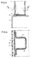
- This shrinkage can be of the order of 15 mm. It limits the visibility of the longitudinal welds by changing the planes. This withdrawal makes it possible advantageously to weld the upright 18 outside the radius of curvature 35 of the spar and to avoid particular machining of the uprights (see FIG. 3).
- Figures 3 and 4 illustrate the withdrawal of a side face relative to its spar.
- the spar 2 is shown seen in cross section in Figure 3.
- the uprights 18 are welded recessed on the spar 2 by welds 32 of MIG type located on the inside of the vehicle.
- the welding of a sheet, for example that bearing the reference 6 in FIGS. 1 and 2, on the spar 2 is carried out by a continuous MIG weld 34 located behind the spar.
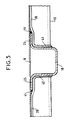
- the profiles of the frameworks of the lateral faces form, at their meeting point, assembly nodes. They are stamped and cut at these assembly nodes to present a flat surface common to these profiles, which surface will be the surface for laying the sheets. This way of proceeding also makes it possible to limit the grinding of the welds on the sheet metal side and eliminating the machining of docking of the profiles. Profiles of different depths allow the assemblies to move the weld out of the radius, which limits deformation, and to eliminate the notches in the bending radius. This is illustrated by FIG. 5 which represents the profile 18 in section and the profile 19 seen from above.
- Profile 19 is shallower than profile 18. Profile 19 is interrupted at the assembly node. Its wings 20 are stamped at this level and folded down behind the wings 25.
- MIG welds 41, 42, 43 and 44 ensure the connection of the two profiles, the welds being made outside the radius. This way of arranging the profiles provides a flat surface for fixing the sheet 8 which can be fixed both on the profile 18 and on the profile 19.
- the sheet elements can be reinforced by a fluted profile serving as a stiffener.
- This fluted profile in stainless steel can be fixed to the sheet by two-point resistant welds which hardly mark the visible surface.
- FIG. 6 shows a sheet metal element 36 reinforced, on its internal face of the vehicle, by a grooved profile 37.
- Two profiles 38 and 39 of the resistant structure of the body are also shown on which the sheet metal element 36 is fixed .
- the reinforcement eliminates the operation of tensioning the sheets between bays carried out on the body. At the end of the body, where the sheet tension is impossible, the use of reinforced sheets is imperative.
- FIG. 7 a cross-member on the lateral face 19 is recognized on which the edge of a sheet metal 8 is welded by welding points 29
- a discontinuous welding 48 by MIG clapboards is carried out between the edge of the sheet 8 and the cross-member 19.
- the window 47 of the opening is held on the framework of the lateral face and in particular on the cross-member 19 by an opening joint 45
- a cord 46 of sealing mastic has been deposited on the cross-member 19 at the edge of the sheet 8, at the places without welding 48.
- the bay seal 45 has a support lip 49 resting on the sheet 8 and making it possible to hide the spot welds resistant.
- a gasket key 40 inserted in the elastic material of the gasket 45 ensures correct pressure of the gasket on the window 47 on the one hand and on the cross member 19 and the sheet metal 8 on the other hand.
- the surface of the body can then undergo a surface treatment according to the known art to strip the welds and give a uniform appearance to the sheets.
Landscapes
- Engineering & Computer Science (AREA)
- Life Sciences & Earth Sciences (AREA)
- Wood Science & Technology (AREA)
- Mechanical Engineering (AREA)
- Body Structure For Vehicles (AREA)
- Butt Welding And Welding Of Specific Article (AREA)
- Metal Rolling (AREA)
- Arc Welding In General (AREA)
- Fittings On The Vehicle Exterior For Carrying Loads, And Devices For Holding Or Mounting Articles (AREA)
- Vehicle Interior And Exterior Ornaments, Soundproofing, And Insulation (AREA)
- Laminated Bodies (AREA)
Applications Claiming Priority (2)
| Application Number | Priority Date | Filing Date | Title |
|---|---|---|---|
| FR9206734A FR2691937B1 (fr) | 1992-06-03 | 1992-06-03 | Caisse de vehicule ferroviaire en acier inoxydable. |
| FR9206734 | 1992-06-03 |
Publications (2)
| Publication Number | Publication Date |
|---|---|
| EP0573351A1 true EP0573351A1 (de) | 1993-12-08 |
| EP0573351B1 EP0573351B1 (de) | 1995-08-30 |
Family
ID=9430403
Family Applications (1)
| Application Number | Title | Priority Date | Filing Date |
|---|---|---|---|
| EP93401403A Expired - Lifetime EP0573351B1 (de) | 1992-06-03 | 1993-06-02 | Wagenkasten aus rostfreiem Stahl für Schienenfahrzeug |
Country Status (10)
| Country | Link |
|---|---|
| US (1) | US5388529A (de) |
| EP (1) | EP0573351B1 (de) |
| JP (1) | JP2863063B2 (de) |
| KR (1) | KR100260564B1 (de) |
| AT (1) | ATE127078T1 (de) |
| AU (1) | AU657620B2 (de) |
| CA (1) | CA2097550C (de) |
| DE (1) | DE69300412T2 (de) |
| ES (1) | ES2076053T3 (de) |
| FR (1) | FR2691937B1 (de) |
Cited By (4)
| Publication number | Priority date | Publication date | Assignee | Title |
|---|---|---|---|---|
| EP0790168A1 (de) * | 1996-02-13 | 1997-08-20 | Hoogovens Aluminium Profiltechnik Bonn GmbH | Wagenkastenaufbau |
| EP1935743A1 (de) | 2006-12-21 | 2008-06-25 | ALSTOM LHB GmbH | Eisenbahngüterwagen mit seitlichen Schiebewänden |
| WO2014187794A1 (de) * | 2013-05-24 | 2014-11-27 | Siemens Aktiengesellschaft | Bausatz zur herstellung eines schienenfahrzeugs mit flexiblem tür- und fensterteiler |
| FR3120044A1 (fr) * | 2021-02-24 | 2022-08-26 | Speedinnov | Panneau de véhicule, véhicule et procédé de fabrication d’un panneau de véhicule associés |
Families Citing this family (17)
| Publication number | Priority date | Publication date | Assignee | Title |
|---|---|---|---|---|
| US5194228A (en) * | 1990-10-12 | 1993-03-16 | General Signal Corporation | Fluidized bed apparatus for chemically treating workpieces |
| DE19528035A1 (de) * | 1995-07-31 | 1997-02-06 | Krauss Maffei Verkehrstechnik | Führerraum für den Wagenkasten eines Schienenfahrzeugs |
| US6581819B1 (en) * | 1996-03-19 | 2003-06-24 | Hitachi, Ltd. | Panel structure, a friction stir welding method, and a panel |
| JP3070735B2 (ja) | 1997-07-23 | 2000-07-31 | 株式会社日立製作所 | 摩擦攪拌接合方法 |
| DE19903281A1 (de) * | 1999-01-28 | 2000-08-03 | Abb Daimler Benz Transp | Schienenfahrzeug mit selbsttragendem Wagenkasten |
| SE0002138L (sv) * | 2000-06-07 | 2001-12-08 | Bombardier Transp Gmbh | Vagnkorgshölje hos ett rälsgående fordon |
| JP3563045B2 (ja) * | 2000-09-11 | 2004-09-08 | 株式会社日立製作所 | 鉄道車両 |
| CA2420300C (en) * | 2002-03-01 | 2006-11-14 | Bombardier Transportation (Technology) Germany Gmbh | Undercar assembly for a railcar |
| US6978720B2 (en) * | 2003-10-28 | 2005-12-27 | Johnson Kent N | Gondola railcar construction |
| DE102007022198A1 (de) * | 2007-05-11 | 2008-11-13 | Siemens Ag | Bausatz für eine Wagenkasten-Rohbaustruktur |
| JP2009166553A (ja) * | 2008-01-11 | 2009-07-30 | Tokyu Car Corp | 鉄道車両構体 |
| KR101081841B1 (ko) | 2009-09-22 | 2011-11-09 | 현대로템 주식회사 | 철도차량 차체의 사이드 구조체 및 이의 제조방법 |
| JP5869389B2 (ja) * | 2012-03-22 | 2016-02-24 | 株式会社総合車両製作所 | 鉄道車両用外板、鉄道車両構体、及び鉄道車両構体の製造方法 |
| AT518382B1 (de) * | 2016-02-17 | 2017-12-15 | Siemens Ag Oesterreich | Wagenkasten für ein Passagierschienenfahrzeug |
| FR3065488B1 (fr) * | 2017-04-20 | 2019-06-28 | Faurecia Systemes D'echappement | Element de ligne d'echappement et procede de fabrication d'un tel element |
| DE102021208471A1 (de) | 2021-08-04 | 2023-02-09 | Siemens Mobility GmbH | Dachkonstruktion für einen Wagenkasten für ein Schienenfahrzeug |
| KR20230133128A (ko) * | 2022-03-10 | 2023-09-19 | 현대자동차주식회사 | 차량의 어퍼바디 이너패널 조립체 |
Citations (4)
| Publication number | Priority date | Publication date | Assignee | Title |
|---|---|---|---|---|
| US2620750A (en) * | 1948-11-01 | 1952-12-09 | Budd Co | Panel and panel cover, especially for railway cars |
| US2815722A (en) * | 1948-11-01 | 1957-12-10 | Budd Co | Marginal rail for cover strip retaining panels, especially for railway car |
| US2870723A (en) * | 1954-06-29 | 1959-01-27 | Pullman Standard Car Mfg Co | Railway car side wall |
| DE2031546A1 (de) * | 1970-03-18 | 1971-09-30 | VEB Waggonbau Görlitz, χ 8900 Gor htz | Ausbildung und Anordnung von Montage einheiten fur Wagenkasten, insbesondere doppelstockiger Bauart |
Family Cites Families (13)
| Publication number | Priority date | Publication date | Assignee | Title |
|---|---|---|---|---|
| BE480233A (de) * | 1941-05-09 | |||
| US3347175A (en) * | 1965-03-09 | 1967-10-17 | Youngstown Steel Door Co | Railroad car side sill construction |
| US3461819A (en) * | 1967-08-22 | 1969-08-19 | Budd Co | Vehicle body construction and method of making it |
| US3672309A (en) * | 1970-07-13 | 1972-06-27 | Pullman Inc | Welded light alloy car construction |
| JPH0245258A (ja) * | 1988-08-05 | 1990-02-15 | Hitachi Ltd | 車両の構体構造 |
| US5267515A (en) * | 1989-01-18 | 1993-12-07 | Hitachi, Ltd. | Vehicle body construction having longitudinally elongated extruded panels and continuous welds joining the panels |
| JPH0645340B2 (ja) * | 1989-01-18 | 1994-06-15 | 株式会社日立製作所 | 車両の構体ブロック製作方法および構体構造 |
| EP0405889B1 (de) * | 1989-06-30 | 1997-08-27 | Hitachi, Ltd. | Reisezugwagenstrukturen und deren Herstellungsverfahren |
| JPH0348062A (ja) * | 1989-07-12 | 1991-03-01 | Kubota Corp | 作業車の走行変速構造 |
| EP0412794A3 (en) * | 1989-08-09 | 1991-10-30 | Hitachi, Ltd. | Car body for railway rolling stock |
| JP2904828B2 (ja) * | 1989-11-27 | 1999-06-14 | 富士重工業株式会社 | 車両の車体構造 |
| SE466798B (sv) * | 1990-06-06 | 1992-04-06 | Aluminiumbuss I Piteaa Ab | Karosserikropp |
| JP3040522B2 (ja) * | 1991-05-01 | 2000-05-15 | 株式会社日本コンラックス | 光学式情報記録再生装置 |
-
1992
- 1992-06-03 FR FR9206734A patent/FR2691937B1/fr not_active Expired - Lifetime
-
1993
- 1993-06-01 AU AU39934/93A patent/AU657620B2/en not_active Expired
- 1993-06-02 US US08/070,679 patent/US5388529A/en not_active Expired - Lifetime
- 1993-06-02 CA CA002097550A patent/CA2097550C/fr not_active Expired - Lifetime
- 1993-06-02 AT AT93401403T patent/ATE127078T1/de active
- 1993-06-02 EP EP93401403A patent/EP0573351B1/de not_active Expired - Lifetime
- 1993-06-02 DE DE69300412T patent/DE69300412T2/de not_active Expired - Lifetime
- 1993-06-02 KR KR1019930009862A patent/KR100260564B1/ko not_active Expired - Lifetime
- 1993-06-02 ES ES93401403T patent/ES2076053T3/es not_active Expired - Lifetime
- 1993-06-03 JP JP5157918A patent/JP2863063B2/ja not_active Expired - Fee Related
Patent Citations (4)
| Publication number | Priority date | Publication date | Assignee | Title |
|---|---|---|---|---|
| US2620750A (en) * | 1948-11-01 | 1952-12-09 | Budd Co | Panel and panel cover, especially for railway cars |
| US2815722A (en) * | 1948-11-01 | 1957-12-10 | Budd Co | Marginal rail for cover strip retaining panels, especially for railway car |
| US2870723A (en) * | 1954-06-29 | 1959-01-27 | Pullman Standard Car Mfg Co | Railway car side wall |
| DE2031546A1 (de) * | 1970-03-18 | 1971-09-30 | VEB Waggonbau Görlitz, χ 8900 Gor htz | Ausbildung und Anordnung von Montage einheiten fur Wagenkasten, insbesondere doppelstockiger Bauart |
Cited By (4)
| Publication number | Priority date | Publication date | Assignee | Title |
|---|---|---|---|---|
| EP0790168A1 (de) * | 1996-02-13 | 1997-08-20 | Hoogovens Aluminium Profiltechnik Bonn GmbH | Wagenkastenaufbau |
| EP1935743A1 (de) | 2006-12-21 | 2008-06-25 | ALSTOM LHB GmbH | Eisenbahngüterwagen mit seitlichen Schiebewänden |
| WO2014187794A1 (de) * | 2013-05-24 | 2014-11-27 | Siemens Aktiengesellschaft | Bausatz zur herstellung eines schienenfahrzeugs mit flexiblem tür- und fensterteiler |
| FR3120044A1 (fr) * | 2021-02-24 | 2022-08-26 | Speedinnov | Panneau de véhicule, véhicule et procédé de fabrication d’un panneau de véhicule associés |
Also Published As
| Publication number | Publication date |
|---|---|
| JPH06156272A (ja) | 1994-06-03 |
| KR100260564B1 (ko) | 2000-07-01 |
| CA2097550C (fr) | 1998-02-10 |
| EP0573351B1 (de) | 1995-08-30 |
| JP2863063B2 (ja) | 1999-03-03 |
| DE69300412D1 (de) | 1995-10-05 |
| ATE127078T1 (de) | 1995-09-15 |
| AU657620B2 (en) | 1995-03-16 |
| AU3993493A (en) | 1993-12-09 |
| DE69300412T2 (de) | 1996-02-01 |
| CA2097550A1 (fr) | 1993-12-04 |
| FR2691937A1 (fr) | 1993-12-10 |
| FR2691937B1 (fr) | 1994-07-22 |
| US5388529A (en) | 1995-02-14 |
| ES2076053T3 (es) | 1995-10-16 |
| KR940000326A (ko) | 1994-01-03 |
Similar Documents
| Publication | Publication Date | Title |
|---|---|---|
| EP0573351B1 (de) | Wagenkasten aus rostfreiem Stahl für Schienenfahrzeug | |
| RU2555460C2 (ru) | Внешняя стенка для кузова вагона рельсового транспортного средства и способ его изготовления | |
| US8844871B2 (en) | Aircraft fuselage structural components and methods of making same | |
| KR101919175B1 (ko) | 철도 차량 차체와 그 제조 방법 | |
| JP5892140B2 (ja) | 車体部材の接合構造の製造方法及び車体構造の製造方法 | |
| US20110148172A1 (en) | Structural part, vehicle seat comprising a back rest, and method for producing a structural part or a back rest | |
| CA2296755A1 (fr) | Paroi laterale pour vehicule ferroviaire et caisse de vehicule ferroviaire correspondante | |
| US10745060B2 (en) | Vehicle pillar structure and method for manufacturing vehicle pillar | |
| US10300957B2 (en) | Vehicles and vehicle roof structures including front header extensions | |
| WO2019229074A1 (fr) | Porte de cabine pressurisée d'aéronef à structure formée de poutres | |
| CA3132625A1 (fr) | Porte de cabine pressurisee d'aeronef a armature interieure de reprise d'efforts | |
| EP0618124B1 (de) | Schienenfahrzeug aus Schalenprofilen konstruiert | |
| JP7064999B2 (ja) | 建設機械用キャブ | |
| FR2811741A1 (fr) | Procede de fabrication d'un element de structure ayant une paroi metallique de forme generale tubulaire et element de structure | |
| EP2172382B1 (de) | Schienenfahrzeug Wagenkasten und entsprechendes Herstellungsverfahren | |
| RU2601094C1 (ru) | Конструкция задней части кузова транспортного средства | |
| JP3171814B2 (ja) | 車両の側構体 | |
| FR2753676A1 (fr) | Structure de chassis de vehicule automobile | |
| JP7112643B2 (ja) | 車両のボディ構造 | |
| JPH0645340B2 (ja) | 車両の構体ブロック製作方法および構体構造 | |
| JP2734328B6 (ja) | 鉄道車両の車体 | |
| JP2734328B2 (ja) | 鉄道車両の車体 | |
| CN209904877U (zh) | 车辆侧部结构 | |
| FR3054818A1 (fr) | Structure de pavillon pour toit ouvrant, formant renfort de caisse. | |
| FR3056539A1 (fr) | Structure de caisse de vehicule ferroviaire |
Legal Events
| Date | Code | Title | Description |
|---|---|---|---|
| PUAI | Public reference made under article 153(3) epc to a published international application that has entered the european phase |
Free format text: ORIGINAL CODE: 0009012 |
|
| AK | Designated contracting states |
Kind code of ref document: A1 Designated state(s): AT CH DE ES FR GB IT LI SE |
|
| 17P | Request for examination filed |
Effective date: 19940413 |
|
| 17Q | First examination report despatched |
Effective date: 19950126 |
|
| GRAA | (expected) grant |
Free format text: ORIGINAL CODE: 0009210 |
|
| AK | Designated contracting states |
Kind code of ref document: B1 Designated state(s): AT CH DE ES FR GB IT LI SE |
|
| REF | Corresponds to: |
Ref document number: 127078 Country of ref document: AT Date of ref document: 19950915 Kind code of ref document: T |
|
| ITF | It: translation for a ep patent filed | ||
| REF | Corresponds to: |
Ref document number: 69300412 Country of ref document: DE Date of ref document: 19951005 |
|
| REG | Reference to a national code |
Ref country code: ES Ref legal event code: FG2A Ref document number: 2076053 Country of ref document: ES Kind code of ref document: T3 |
|
| GBT | Gb: translation of ep patent filed (gb section 77(6)(a)/1977) |
Effective date: 19950918 |
|
| PLBQ | Unpublished change to opponent data |
Free format text: ORIGINAL CODE: EPIDOS OPPO |
|
| PLBI | Opposition filed |
Free format text: ORIGINAL CODE: 0009260 |
|
| PLBF | Reply of patent proprietor to notice(s) of opposition |
Free format text: ORIGINAL CODE: EPIDOS OBSO |
|
| 26 | Opposition filed |
Opponent name: MANFRED KIRCHHOFF TECHNISCHE BERATUNG Effective date: 19960529 |
|
| PLAB | Opposition data, opponent's data or that of the opponent's representative modified |
Free format text: ORIGINAL CODE: 0009299OPPO |
|
| R26 | Opposition filed (corrected) |
Opponent name: SGP VERKEHRSTECHNIK GMBH Effective date: 19960529 |
|
| PLBF | Reply of patent proprietor to notice(s) of opposition |
Free format text: ORIGINAL CODE: EPIDOS OBSO |
|
| PLBO | Opposition rejected |
Free format text: ORIGINAL CODE: EPIDOS REJO |
|
| PLBN | Opposition rejected |
Free format text: ORIGINAL CODE: 0009273 |
|
| STAA | Information on the status of an ep patent application or granted ep patent |
Free format text: STATUS: OPPOSITION REJECTED |
|
| 27O | Opposition rejected |
Effective date: 19981224 |
|
| REG | Reference to a national code |
Ref country code: GB Ref legal event code: IF02 |
|
| PGFP | Annual fee paid to national office [announced via postgrant information from national office to epo] |
Ref country code: DE Payment date: 20120622 Year of fee payment: 20 Ref country code: CH Payment date: 20120622 Year of fee payment: 20 |
|
| PGFP | Annual fee paid to national office [announced via postgrant information from national office to epo] |
Ref country code: SE Payment date: 20120621 Year of fee payment: 20 Ref country code: GB Payment date: 20120622 Year of fee payment: 20 Ref country code: FR Payment date: 20120705 Year of fee payment: 20 |
|
| PGFP | Annual fee paid to national office [announced via postgrant information from national office to epo] |
Ref country code: ES Payment date: 20120627 Year of fee payment: 20 Ref country code: IT Payment date: 20120627 Year of fee payment: 20 |
|
| PGFP | Annual fee paid to national office [announced via postgrant information from national office to epo] |
Ref country code: AT Payment date: 20120613 Year of fee payment: 20 |
|
| REG | Reference to a national code |
Ref country code: DE Ref legal event code: R071 Ref document number: 69300412 Country of ref document: DE |
|
| REG | Reference to a national code |
Ref country code: CH Ref legal event code: PL |
|
| REG | Reference to a national code |
Ref country code: GB Ref legal event code: PE20 Expiry date: 20130601 |
|
| REG | Reference to a national code |
Ref country code: AT Ref legal event code: MK07 Ref document number: 127078 Country of ref document: AT Kind code of ref document: T Effective date: 20130602 |
|
| PG25 | Lapsed in a contracting state [announced via postgrant information from national office to epo] |
Ref country code: GB Free format text: LAPSE BECAUSE OF EXPIRATION OF PROTECTION Effective date: 20130601 Ref country code: DE Free format text: LAPSE BECAUSE OF EXPIRATION OF PROTECTION Effective date: 20130604 |
|
| REG | Reference to a national code |
Ref country code: ES Ref legal event code: FD2A Effective date: 20140828 |
|
| PG25 | Lapsed in a contracting state [announced via postgrant information from national office to epo] |
Ref country code: ES Free format text: LAPSE BECAUSE OF EXPIRATION OF PROTECTION Effective date: 20130603 |